Enabling Branch Dynamic Routing
This topic describes dynamic routing configuration. It includes these sections:
Dynamic routing overview
To simplify integration into existing networks and provide flexible routing, SteelConnect leverages the Border Gateway Protocol (BGP) and the Open Shortest Path First (OSPF) protocol version 2.
•BGP - A Layer 4 protocol that exchanges routing information between peers to determine the optimal paths for traffic flows. Through the SteelConnect Manager (SCM), you enable SteelConnect gateways to use BGP to advertise all of their associated LAN zones (IP subnets) to an upstream router in the MPLS provider’s BGP environment. For details on zones, see
Zones within a site.
•OSPF - A Layer 3 link state protocol for routing traffic information within a single area. OSPF selects the most suitable and shortest data path for network traffic. A SteelConnect gateway in the branch learns routes dynamically from other routers in the OSPF routing domain and advertises the routes it learns. Routes specifically on the LAN-side of a SteelConnect gateway are published into the AutoVPN.
Routing feature support by model
Feature | SteelHead-SD 570-SD, 770-SD, 3070-SD | SDI-2030 | SDI-130 | SDI-330 | SDI-1030 | SDI-5030 | Virtual GW |
eBGP | Yes | Yes | Yes | Yes | Yes | Yes | Yes |
iBGP | Yes | Yes | No | No | No | No | No |
OSPF single area | Yes | Yes | Yes | Yes | Yes | No | No |
OSPF multi-area ABR | Yes | Yes | No | No | No | No | No |
ASBR | Yes | Yes | Yes* (Underlay routing inter-working solution) | Yes* (Underlay routing inter-working solution) | Yes* (Underlay routing inter-working solution) | No | Yes* (Underlay routing inter-working solution) |
Route retraction | Yes | Yes | No | No | No | Yes | No |
Default route originate | OSPF/BGP | OSPF/BGP LAN and WAN | OSPF only LAN | OSPF only LAN | OSPF only LAN | BGP only | OSPF only LAN |
Overlay route injection in LAN | Yes | Yes | No | No | No | Yes | No |
Local subnet discovery | Yes | Yes | No | No | No | Yes | No |
Static routes | Yes | Yes (LAN and WAN) | Yes (third-party routes) | Yes (third-party routes) | Yes (third-party routes) | Yes | Yes (third-party routes) |
VLAN support (LAN side) | Yes | Yes | Yes | Yes | Yes | Yes | Yes |
*SCM 2.9 and later support an underlay routing interworking solution that bridges BGP and OSPF. For details, see
Redistributing underlay routing.
Why enable dynamic routing?
Without eBGP or OSPF, gateways use static routing to directly connect manually configured routes that access a single default route. This type of routing is suitable for small networks, but managing the static configurations becomes very time-consuming as network routing choices expand.
Benefits of dynamic routing with OSPF
Dynamic routing with OSPF on the LAN side provides reachability to multiple network prefixes over a single OSPF zone interface. All of the networks learned from an OSPF zone interface are mapped to the OSPF area that the interface is connected to.
When an OSPF-enabled uplink connects to a customer edge (CE) router, the gateway acts as a CE router to distribute routes between OSPF on the LAN side and eBGP running on the WAN side.
OSPF provides flexible subnet management as follows:
•The gateway learns local networks from the OSPF area that the zone interface is connected to.
•The gateway maps the learned networks to the zone.
•When the zone is member of a WAN, all of the networks learned from that OSFP area become routable over the WAN.
•While the peering session is up, the neighbors will send updates about a new route or the need to withdraw a previous announcement.
Benefits of dynamic routing with eBGP
eBGP provides flexible subnet management in an MPLS network in these ways:
•Instead of sending static routes, the gateway sends dynamic zone advertisements through an uplink.
•A gateway can advertise all available IPv4 and IPv6 zones (subnets) to an MPLS provider’s eBGP environment. All of the eBGP-connected sites in the MPLS become aware of the zones offered by the gateway.
•The uplink advertises a site’s local network zones (LAN and virtual IP pools) and third-party routes. Guest zones are not advertised.
•The gateway learns about remote IPv4 and IPv6 zones through eBGP from the MPLS autonomous system (AS), including both gateway-based sites and CE router-based sites.
•While the peering session is up, the neighbors will send eBGP updates from one to the other each time one of the neighbors knows about a new BGP route or needs to withdraw a previous announcement.
•The uplink can also advertise third-party redistributed zones.
CE and PE routers
Customer edge (CE) routers and provider edge (PE) routers are components in an MPLS architecture. A CE router is located on the customer premises. It provides an Ethernet interface between the customer’s LAN and the provider’s core network. PE routers sit at the edge of the network. CE routers connect to PE routers. SteelConnect gateways also connect to PE routers.
A SteelConnect gateway can replace a CE router to advertise and receive route announcements from the MPLS underlay.
BGP
With BGP enabled, a SteelConnect gateway establishes a TCP IPv4 control channel connection over static uplinks to a neighbor on the WAN side of an MPLS network. An established neighbor can then receive BGP updates using this peering session. The gateway shares all of the BGP routes inside its private network with its BGP neighbor. The BGP neighbor shares its BGP remote subnet routes from the IP-based virtual private network (VPN), and the gateway learns the routes.
When the BGP neighbor router in the MPLS WAN becomes aware of all LAN zones offered by the gateway, it can then learn and establish reachability to the gateway’s LAN zones. When the gateway learns all of the BGP remote subnet routes, it can then establish reachability to the remote subnets.
BGP is configured differently on a data center gateway. For details on data center dynamic routing, see
Why enable dynamic routing for a cluster?.
BGP modes
BGP can run in two modes that have different behavior when advertising routing information: eBGP and iBGP. Both modes share the same low-level protocol for exchanging routes, but external BGP (eBGP) runs between routers in different autonomous systems.
An autonomous system (AS) is a single network or a set of networks and routers that are managed and supervised by a common network administrator (or group of administrators) on behalf of a single administrative entity, such as a business division. An AS is assigned a globally unique number that identifies the network to the world.
Internal BGP (iBGP) runs between routers in the same AS.
SCM dynamic routing uses eBGP and not iBGP.
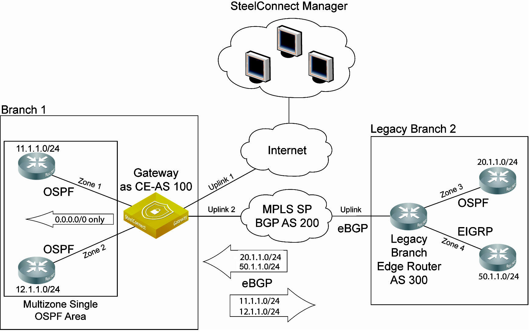
Branch dynamic routing topologies with eBGP
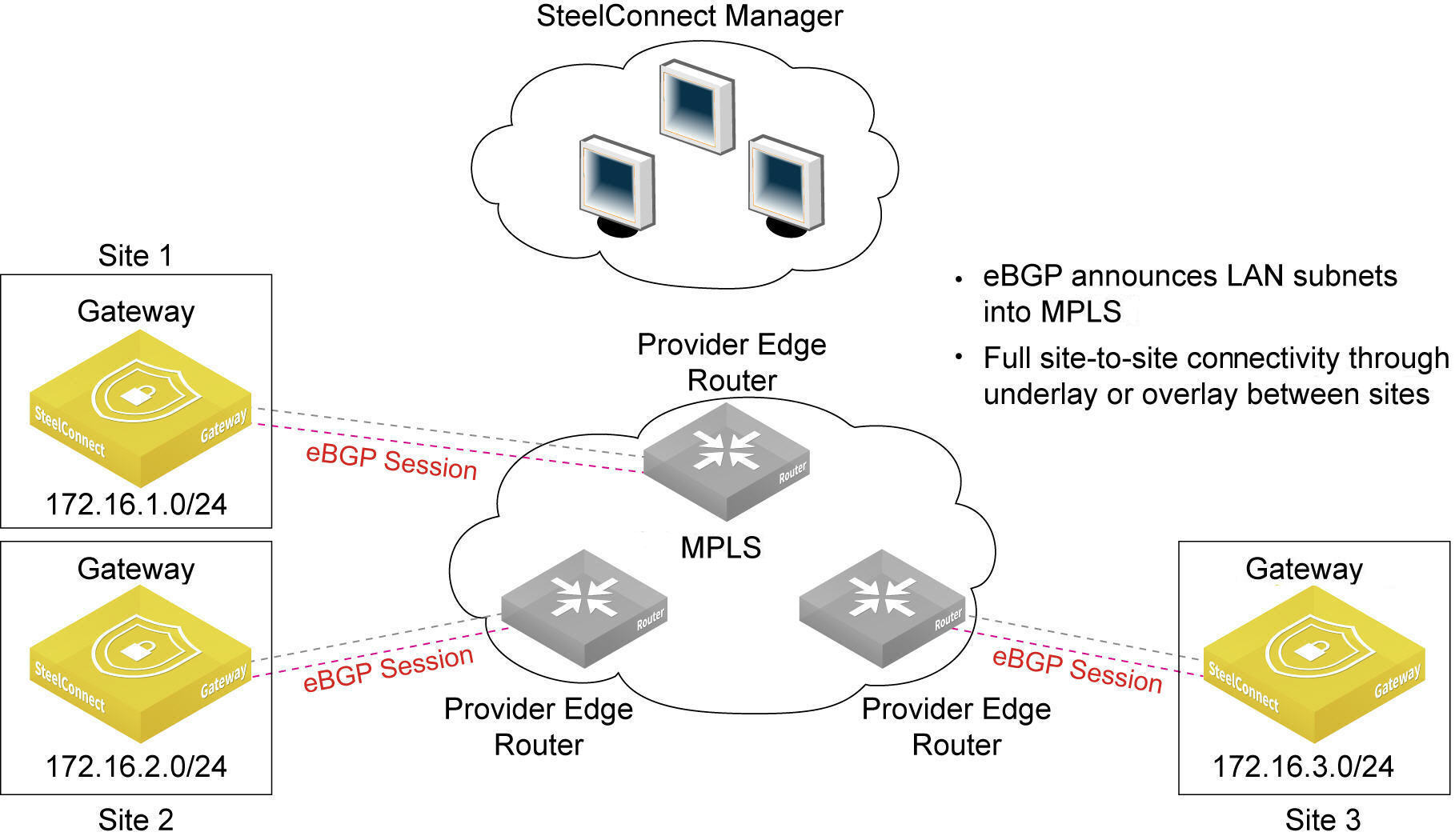
BGP supports the topology as shown in
An eBGP deployment for gateways behind intermediate PE routers. The figure shows three sites. Each site has a gateway, and each gateway is behind an intermediate provider edge (PE) router.
An eBGP deployment for gateways behind intermediate PE routers
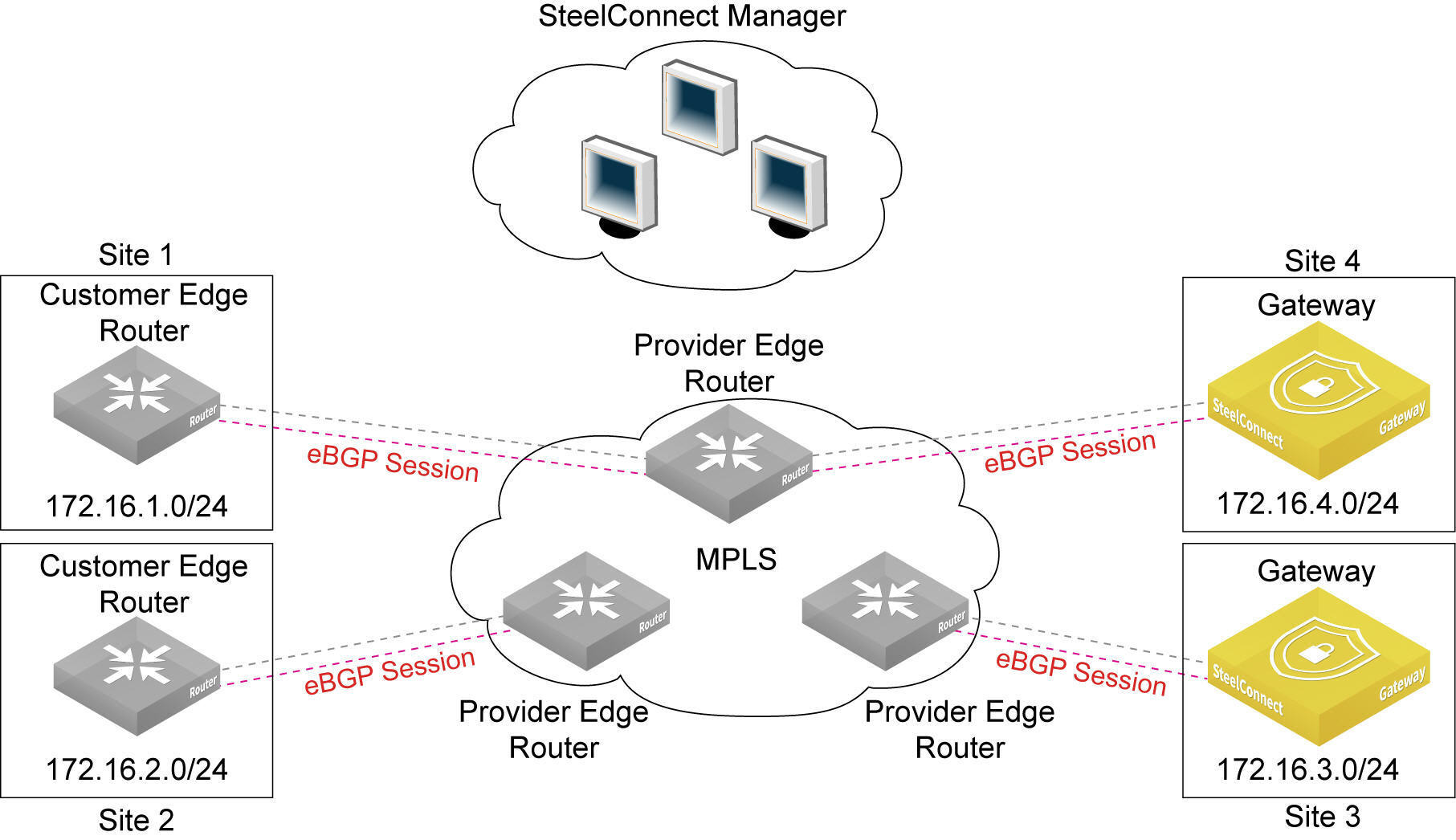
In addition to the topology shown in
An eBGP deployment for gateways behind intermediate PE routers, SteelConnect supports the topology shown in
An eBGP deployment with route learning from remote site, which shows four sites. This deployment supports route learning from remote sites (site 1 and site 2) with subnets behind a third-party customer edge router.
An eBGP deployment
with route learning from remote site
New sites are connected to the MPLS through the SteelConnect gateway. The gateway uses eBGP to advertise its LAN-side subnets into the MPLS AS.
The advertised subnets are propagated to all existing CE-based sites and also to the gateway sites.
The gateway learns about remote IP subnets from the MPLS AS, including both gateway-based sites and CE-based sites.
You can enable Message Digest 5 (MD5) authentication between two eBGP neighbors to have SteelConnect verify each segment sent on the TCP connection between the neighbors.
Communication between gateways, sites, and routers
•The gateway sites communicate through the underlay or overlay.
•The CE router-based sites communicate with each other through the MPLS underlay only.
•The CE router-based sites communicate with the gateway sites through the MPLS underlay only.
•A CE router communicates with another CE router through the MPLS underlay only.
The maximum number of learned and advertised routes is 3000 across all gateway models. If the number of prefixes advertised by the PE exceeds 3000, SteelConnect brings down the eBGP peer connection with the PE. After the connection is disabled, you must disable and subsequently reenable the BGP uplink on the SCM side. To view the message indicating that the limit was reached, click the Events tab or select Visibility > Event log.
For data center dynamic routing topology, see
Why enable dynamic routing for a cluster?.
When an SDI branch gateway or a SteelHead SD appliance receives an eBGP route that includes its own AS number as an AS path attribute, it will deny the route and drop it to prevent a BGP route loop. This is the expected behavior with BGP. As a workaround, you can override the AS number for the PE peer router using the "as-override" command to remove the outbound AS number from the AS-path loop check. The AS number override allows the route when it is received on the SDI branch gateway or SteelHead SD appliance.
Enabling BGP on a branch gateway
This section describes how to enable eBGP on SDI-130, SDI-330, and SDI-1030 branch gateways. By default, eBGP is disabled.
The BGP tab on SteelHead SD 570-SD, 770-SD, and 3070-SD appliances and the SDI-2030 gateway includes additional fields. For details, see
Configuring BGP on SteelHead SD in the
SteelHead SD User Guide.
To enable BGP
1. Choose Appliances.
2. Select a branch gateway.
3. Select the BGP tab.
Enabling eBGP
4. Fill out these required session attributes:
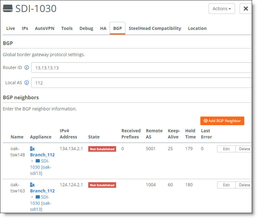
•Router ID - Specify the router IPv4 or IPv6 address to uniquely identify the router in the local autonomous system (AS). The gateway can peer with any remote router that supports eBGP. eBGP must be enabled on the router. If another uplink is configured with a router ID on the same appliance, SCM defaults to the same router ID used on the previously configured uplink and you can’t change the setting.
•Local AS - Specify the AS number the router belongs to: for example, 100. The range is from 1 to 4294967295. The default setting is 65000. If another uplink is configured with a local AS on the same appliance, SCM defaults to the same local AS setting used on the previously configured uplink and you can’t change the setting.
5. Click Submit.
6. Repeat this process for gateways behind other routers; if you have two MPLS providers, you need to create a BGP configuration for each one.
Creating an eBGP neighbor
This section describes how to establish eBGP neighbors.
To create a BGP neighbor
1. Choose Appliances.
2. Select a branch gateway.
3. Click Add BGP Neighbor.
Creating an eBGP neighbor
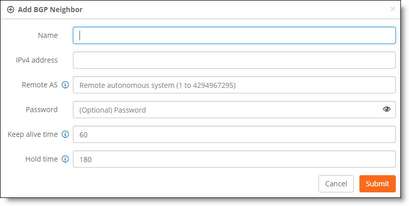
4. Fill out these required session attributes:
•Name - Specify the peer name for the provider. Each uplink can support one eBGP peer.
•IPv4 Address - Specify the peer IPv4 address.
•Remote AS - Specify the autonomous system number the peer belongs to: for example, 200. The range is from 1 to 4294967295. If another uplink is configured with a remote AS on the same appliance, SCM defaults to the same remote AS setting used on the previously configured uplink and you can’t change the setting.
•Password - Optionally, type a password to enable MD5 authentication. You must use the same password on both BGP neighbors. If you don’t require MD5 authentication you can leave this field blank.
Click the eye icon to see the password as you type. The view persists until you click the eye icon again to hide the password.
•Keep Alive Time - Specify the amount of time, in seconds, that the eBGP neighbors exchange keepalive messages to determine whether a link has failed or is no longer available. The neighbors exchange keepalive messages often enough so that the hold time does not expire. The default setting is 60.
•Hold Time - Specify the amount of time, in seconds, that a gateway neighbor waits for an incoming keepalive, update, or notification message from a neighbor before it assumes its neighbor is down. If the gateway doesn’t receive a keepalive, update, or notification message from its neighbor within the period specified, it closes the connection and routing through that neighbor becomes unavailable.
A 0 value means that no keepalive messages are sent and the connection will never close. The hold-time range is from 0 to 65535. The default setting is 180.
The hold-time value is three times the interval at which keepalive messages are sent. Using the default values for the keepalive time of 60 and the hold time of 180, the settings work together like this: after two neighbors establish an eBGP session, 60 seconds later they’ll each send a keepalive message. When a gateway receives a keepalive message from its neighbor, that gateway’s hold time for the session will have counted down from 180 to 120, but it’s then reset to 180. This process continues every 60 seconds. However, should neighbor A lose power, then neighbor B won’t receive any keepalives. So after 180 seconds, neighbor B determines that neighbor A is down and closes the session.
5. Click Submit.
6. Repeat this process for gateways behind other routers; if you have two MPLS providers, you need to create a BGP configuration for each one.
Enabling eBGP on static IP uplinks
To establish point-to-point connections between neighbors, you configure an eBGP session on a static IP uplink for a gateway and define its eBGP neighbor. Uplinks using DHCP don’t support eBGP.
If BGP is already attached to an uplink you cannot configure OSPF on the same uplink. If the uplink is already attached to the OSPF area, you cannot configure BGP configuration on the uplink.
To attach an uplink to a BGP neighbor
1. Choose Routing > BGP.
The available uplinks are listed after the appliance. eBGP is only available for static IP uplinks.
If you need to create an uplink, choose Network Design > Uplinks and click New Uplink. Select static IP and type the IP addresses.
2. Click Attach.
Viewing eBGP learned and advertised routes
SCM displays the advertised and learned network routes and peering session state information. To filter the list, type a search filter in the search box, for example, type IPv6 to narrow the search to all IPv6 networks.
To view eBGP network routes per gateway
1. Choose Network Design > Uplinks.
2. Select an uplink with eBGP enabled.
3. Select the Networks tab. The Networks tab is dimmed when eBGP isn’t enabled on the gateway.
The learned and advertised routes for the gateway
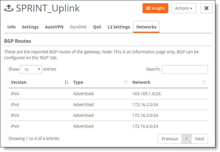
The display shows all advertised and learned network routes for the gateway, along with the route IP version number.
To view eBGP neighbor activity
•Select the Events tab or choose Visibility > Event Log.
The event log records eBGP neighbor status
OSPF
A SteelConnect branch gateway supports OSPF version 2 in a broadcast network for dynamic routing. The gateway uses OSPF zone interfaces connected to LAN segments to learn routes dynamically from other routing devices.
In OSPF, a single AS can be divided into smaller groups called areas. An area is a set of networks and hosts within an AS that are grouped together by an administrator as a collection of IP subnetted networks.
The SteelConnect gateway on the LAN side joins an existing OSPF area in the branch network. You can also create an exclusive area.
An OSPF-enabled gateway discovers and advertises subnets in an MPLS network as follows:
•LAN-side discovered subnets are advertised on the MPLS underlay on the WAN through uplinks attached to the OSPF area. Statically configured zones are not advertised.
•WAN-side subnet discovery and advertisements work like this:
•SCM learns about subnets in a remote SD-WAN site’s OSPF routing domain and configures reachability to the discovered subnets on the overlay tunnel to the remote site.
•Subnets discovered from the WAN side are advertised to the OSPF zone on the LAN side to allow reachability between subnets in the OSPF routing domain across two sites.
•The underlay connectivity between SD-WAN sites and legacy non-SD-WAN sites provides reachability between discovered subnets (assuming that both the sites have connectivity through a common MPLS WAN).
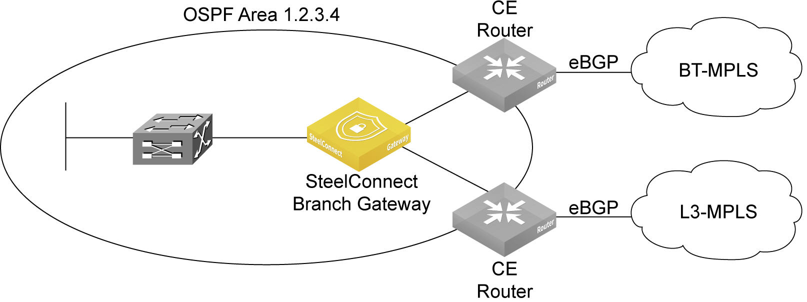
OSPF topology
SteelConnect supports OSPF for a branch site with one or two MPLS providers, where each provider is connected to a CE router. A SteelConnect branch gateway is deployed behind the CE routers. The CE routers on the MPLS WAN side are speaking eBGP and the CE routers on the LAN side are speaking OSPF. Between the CE routers and SCM on the LAN side is the OSPF domain, OSPF area 1.2.3.4 in
An OSPF area with a branch gateway.
An OSPF area with a branch gateway
Configuring OSPF routing
To configure OSPF routing on a gateway, you create an OSPF network, define a single area (or use an existing area), and attach one or more LAN-side zones and/or interfaces to the area.
SCM 2.8 and later simplifies the OSPF configuration for multiple networks. You can configure default values on the General Settings tab and the default values can be inherited by all OSPF networks running on the same gateway. For settings that are acceptable for all of the OSPF networks on a gateway, no individual configuration is necessary other than clicking the Add OSPF Network and Submit buttons.
By default, OSPF is enabled.
Prerequisites
Before configuring OSPF on a gateway, check these requirements.
•The default gateway configuration of the zone must be set to manual mode. To set the default gateway configuration, select the gateway, select the zone, select the Gateways tab, and select Manual.
•The site where the OSPF network is located must already exist.
•OSPF must be enabled on any routing devices that will peer with the gateway.
The basic steps to configure OSPF routing are:
•Create an OSPF network based on a site location that includes one area.
•Attach one or more zones and one or more uplinks to the OSPF area.
To create an OSPF network and area
1. Choose Routing > OSPF.
2. Click Add OSPF Network.
The site selection for the OSPF network automatically populates all fields based on the default settings specified on the OSPF Network > General Settings tab. You can simply click Submit to create a network using the default settings. You don’t have to explicitly configure the settings.
Creating an OSPF network on a branch gateway
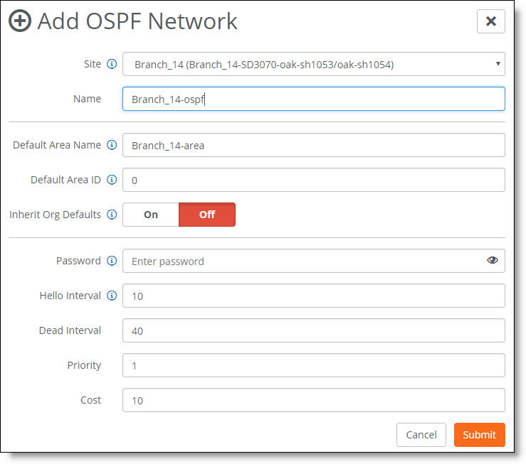
3. Manually fill out the network attributes you don’t want to automatically inherit:
•Site - Select the site where the OSPF network is located. Optionally, leave the site selection blank to select the first site in the list shown on the Network Designs > Sites page. Use this method to save time by quickly creating OSPF networks based on the order in which the sites appear in the site list. Creating another network and leaving the site selection blank again selects the second site in the list, and so on.
•Name - Specify a network name.
•Default Area Name - Specify a name for the area.
•Default Area ID - Specify the area in which the zone resides. Either specify a 32-bit unsigned number from 0 to 4294967295 or a value in the IPv4 address format using dotted decimal notation (x.x.x.x). The default setting is the backbone area ID 0; however, you can change the value to your existing area ID. For small LANs, area 0 might be all you need, but as a network grows, you’ll need more than one area connecting to area 0.
For a routing device to become an OSPF neighbor with another device, both devices must belong to the same area ID and their passwords and authentication methods must match.
•Inherit Org Defaults - Click On to allow the OSPF network and area to automatically inherit the general settings specified on the OSPF Network > General Settings tab.
When enabled, any change to the organization also changes the OSPF network settings. Click Off to define unique settings for the network and to lock the network configuration so any changes don’t overwrite the settings.
•Password - Specify a password.
The authentication methods appear when typing a password. All OSPFv2 exchanges between routing devices can be authenticated using one of these methods:
–MD5 - Select this tab to use the Message Digest 5 algorithm as the authentication method. MD5 authentication enables routing devices to securely identify one another before they establish adjacency. MD5 is a cryptographic hash function with a 128-bit hash value derived from the contents of the OSPF packet and a key and key ID. This method doesn’t send the password but instead calculates and includes an encoded MD5 checksum in the transmitted packet. The receiving routing device uses the key and key ID to verify the packet.
The MD5 key doesn’t have to be the same within the area, but it must be exactly the same between two OSPF neighbors.
Click the eye icon to see the password as you type. The view persists until you click the eye icon again to hide the password.
–Simple - Select this tab to include an unencrypted plain text password with the packet. The receiving routing device uses the password to verify the packet. The simple password can be from one to eight characters and can include ASCII strings. If you include spaces, enclose the password in quotation marks. Use this authentication method when devices within an area don’t support the more secure MD5 authentication, as Simple is the least secure setting.
•MD5 Key ID - (Appears when you select MD5.) Specify a value to associate with the MD5 key. The ID is used by the receiver of the OSPF packet to determine which key to use for authentication.
To change your MD5 key, specify a new key and key ID. When both OSPF neighbors have a new key and key ID, the old key is deleted and the current MD5 key and key ID become active.
•Hello Interval - Specify how often, in seconds, to send a hello packet. Initially the gateway sends a hello packet to all OSPF-enabled interfaces to form an adjacency as a neighbor. The routing devices become neighbors and exchange link-state advertisements. After the gateway learns the common network topology, it sends the hello to check if an OSPF neighbor is alive. The range is from 1 to 65535. The default is 10. The hello interval must be exactly the same between two OSPF neighbors.
•Dead Interval - Specify how many seconds to wait for a hello packet before declaring an OSPF neighbor out of service, triggering a refresh of the link-state database and routing information. The range is from 1 to 65535. The default is 40. The dead interval must be exactly the same between two OSPF neighbors.
•Priority - Specify the priority for becoming the network’s designated routing device. The designated router originates network link advertisements on behalf of the network, and establishes adjacencies with all routing devices on the network.
The routing device that has the highest priority value on the logical IP network or subnet is elected as the designated router. A priority value of 0 means that the routing device never becomes the designated router; it doesn’t even participate in the election process. A value of 1 means that the routing device participates in the election process but has the least chance of becoming a designated router. A priority of 255 means the routing device is always the designated router.
To ensure that a routing device is elected as the designated routing device, configure the priority value to a higher value than any other interface on the Ethernet network. The range is from 0 to 255. The default value is 1.
•Cost - Specify a routing metric used in the link-state calculation. OSPF selects ideal routes by locating destination routes with the least cost. Routes with lower total path metrics are preferred to those with higher path metrics. This setting controls the cost calculation of OSPF network segments. The default formula to calculate the cost for the OSPF metric is dividing the reference bandwidth (100 Mbps by default) by the interface bandwidth. For example, in the case of Ethernet, it is 100 Mbps / 10 Mbps = 10.
You can manipulate the cost by specifying a number within the range of 1 to 65535. 10 is the default setting.
The OSPF network needs a zone and, optionally, one or more uplinks to report OSPF learned routes to SCM.
4. Click Submit.
To attach an OSPF interface:
1. Choose Routing > OSPF.
2. Select an OSPF network.
3. Select the OSPF Interfaces tab.
4. Click Attach Interface.
Attaching an OSPF interface
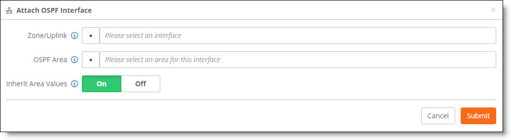
5. Fill out these interface attributes:
•Zone/Uplink - Select the interface on which to enable OSPF communication from the drop-down list. Select one or more zones per area for the LAN side. SCM 2.8 and later allows both management and nonmanagement zones as OSPF interfaces.
If BGP is already configured on an uplink, you cannot configure OSPF on the same uplink. If the uplink is already attached to the OSPF area, you cannot configure BGP configuration on the uplink.
•Inherit Area Values - Click On to allow the interface to automatically inherit the area settings and any changes to an area. When enabled, making a change to the area also changes the OSPF parameters on the interface. Click Off to lock the interface configuration so any changes to the area don’t overwrite the interface parameters.
Click Off to define unique settings for the area.
6. Click Submit.
After you attach the interface to the OSPF area, the gateway configures the zone or zones to run OSPF and establishes OSPF neighbors with LAN routers in the same network segment.
To modify an OSPF network and area
1. Choose Routing > OSPF.
2. Select an OSPF network and click Edit.
Modifying OSPF network default settings
Viewing learned routes
After configuring OSPF, you can monitor learned routes in SCM. When a SteelConnect gateway is participating in an OSPF area, it discovers LAN-side subnets and reports all discovered subnets to SCM. SCM automatically configures discovered remote SD-WAN sites as reachable over the overlay tunnels.
Similarly, network subnets that are discovered on the WAN-side (primarily networks that advertise for the remote site with other SD-WAN or legacy, non-SD-WAN sites) are shown on the Networks tab associated with the uplink by which the gateway discovered those networks.
To view the learned network routes on the LAN side of the OSPF area
1. Choose Network Design > Zones.
2. Select the zone attached to the OSPF area.
3. Select the Learned Networks tab. The Learned Networks tab is dimmed until OSPF is enabled on the gateway.
Learned route details
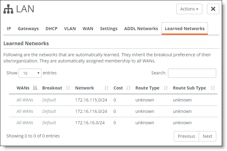
The display shows all advertised and learned network subnets for the gateway, along with the route IP version number and internet breakouts. It takes approximately 30 to 60 seconds for the learned networks to appear.
All learned subnets are automatically reachable on the overlay tunnel between sites.
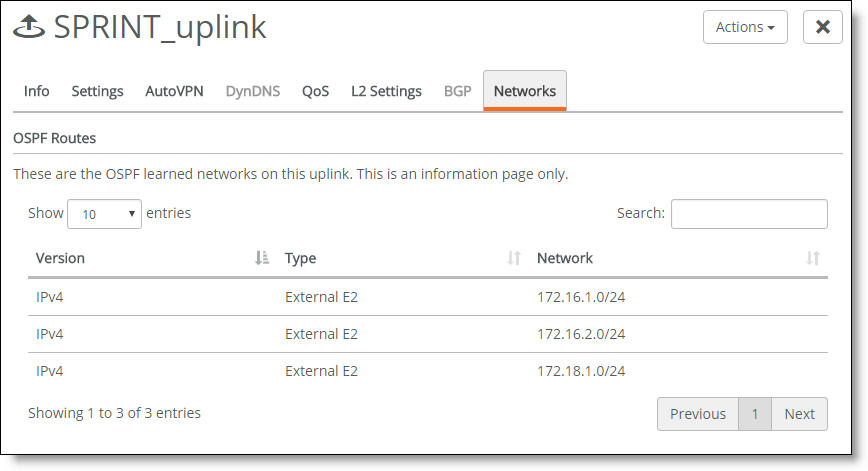
To view the learned network routes on the WAN side of the OSPF area
1. Choose Network Design > Uplinks.
2. Select the uplink attached to the OSPF area.
3. Select the Networks tab.
The WAN side learned routes
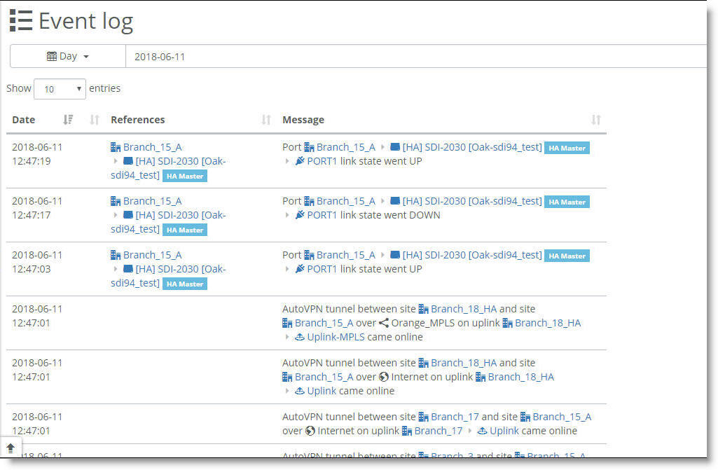
Viewing OSPF neighbor activity
After you connect a zone to an OSPF area, the gateway in the zone initiates neighbor peering with routers in that OSPF area. All neighbor peering activity appears in the event log.
To view OSPF neighbor activity
•Select the Events tab or choose Visibility > Event Log.
The event log records OSPF neighbor activity
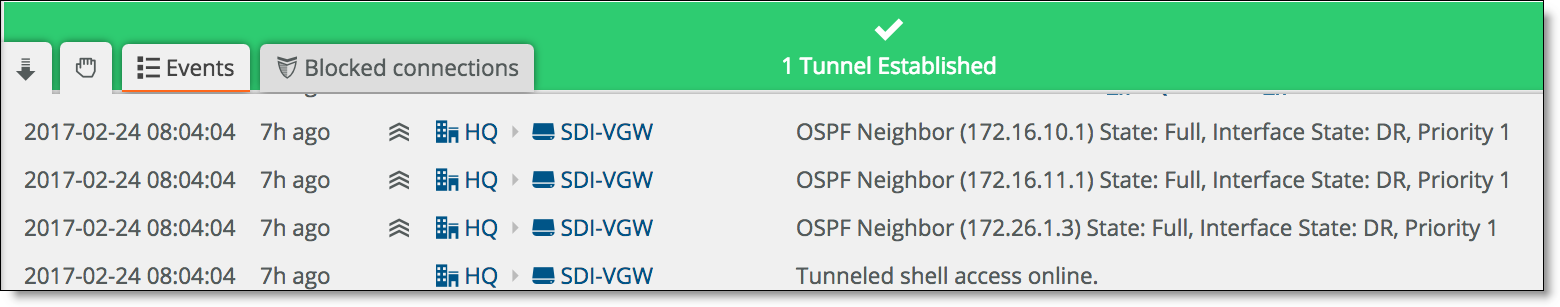
The display shows the OSPF neighbors and their IP addresses, the neighbor state, which neighbor is the designated router (DR), and the neighbor’s interface priority.
How does an OSPF zone interact with traffic rules in SCM?
When your configuration includes traffic rules for balancing traffic or to enable security, an OSPF zone interacts with the rules as follows:
•Traffic rule - You can create a traffic rule for balancing traffic over multiple WANs by selecting a zone either as a source, a target, or both. The traffic rule assigns a specific order of path preference and QoS priority to the source and target combination. When you select a static zone as the source, target, or both, the traffic rule applies to a specific subnet associated with the static zone. However, with a dynamic OSPF zone, the traffic rule provides reachability to a range of subnets learned through that OSPF zone, because the zone is associated with more than one subnet. A traffic rule applies the specified path preference and QoS priority for the rule to all subnets learned from the OSPF zone. For details, see
Directing traffic using traffic rules.
•Outbound or internal rule - You can create an outbound rule that works as a filter to allow or deny traffic between a specific source and target combination. When an OSPF zone is selected as source, a target, or both for an outbound rule, the rule applies to all subnets learned from the OSPF zone.
For details, see
How do inbound and outbound rules work?. Currently, you must create an outbound rule with the OSPF zone as the source to allow TCP traffic originating from any of the OSPF discovered subnets behind the SteelConnect gateway.
Redistributing underlay routing
This section describes how to configure an underlay routing interworking solution between eBGP on the WAN side and OSPF on the LAN side.
The LAN/WAN routing interworking solution bridges eBGP and OSPF to redistribute underlay routing information between the protocols on a gateway.
Underlay routing is supported on SDI-130, SDI-330, and SDI-1030gateways, SDI-VGW virtual gateways, and SteelHead SD 570-SD, 770-SD, and 3070-SD appliances.
Distribution of underlay routing information between eBGP and OSPF
In
Distribution of underlay routing information between eBGP and OSPF, the SteelConnect gateway replaces an existing CE router. The gateway acts as a CE router and distributes routes into the underlay between OSPF on the LAN and eBGP on the uplink (indicated by uplink 2 in
Distribution of underlay routing information between eBGP and OSPF) to an MPLS WAN network.
SteelConnect implements the LAN/WAN routing interworking solution using routing policies to distribute underlay routing information between eBGP and OSPF. LAN (OSPF) routes can be redistributed into eBGP by way of routing policy configuration.
WAN routes are not injected into the LAN. Instead, the gateway injects a default route to itself into the LAN via OSPF. The default route attracts all unknown traffic from the branch devices (indicated by branch 1 in
Distribution of underlay routing information between eBGP and OSPF) toward the gateway.
When unknown LAN traffic reaches the gateway, its route is determined depending on its destination:
On the WAN side, one or more uplinks are participating in the underlay routing, running eBGP, and are peering with a service provider PE router.
On the LAN side, one or more zones are participating in OSPF adjacency with branch internal routers. All zones participating in OSPF adjacency must belong to the same OSPF area.
Routing policy overview
A routing policy determines how routes are redistributed and which routes are summarized. Routing policies are defined per-site and are composed of BGP and OSPF profiles. Use a routing policy as a convenient way to broadly define preferences for the site’s gateway acting as a CE router.
Redistributing routes
Route redistribution includes ways to globally configure:
•redistribution of OSPF routes into eBGP.
Before you begin
Before configuring a routing policy:
•Make sure that there is at least one OSPF-enabled zone available.
•Make sure that there is at least one eBGP-enabled uplink.
•Enable at least one internet breakout for a WAN connection on the site or gateway. The internet breakout provides a safeguard to prevent blackholing of LAN traffic at the gateway when there are no internet break options upstream of the gateway. For details, see
WAN settings.
•OSPF must be disabled on the uplink interfaces.
Summarizing routes
A route summary, also called route aggregation or supernet, condenses routing information. Route summaries distribute routing information into the underlay using a single prefix that represents a set of individual addresses. With route summary, a gateway can distribute a single advertisement, reducing the load on the gateways and routers, improving performance and making it easier to manage a complex network.
Route summary
You can use a route summary to:
•add summary addresses to a BGP profile.
•advertise both summary prefixes and individual prefixes to the BGP peer. This option is configurable per summary address on the WAN side.
When configured, the routing policy advertises a summary address only and not the individual prefixes to a BGP peer. You must add the WAN prefixes for the summary advertisements on the BGP Summarization tab to create a route summary. See
To add, edit, or delete LAN prefix summarization via BGP.
We recommend a maximum of 400 route summaries.
Routing policies only impact the underlay routing. They don’t impact the overlay routing orchestrated by SCM.
Injecting a default route
When configured, the routing policy injects a default route into the OSPF LAN globally. The default route advertises the path to any route not found.
Gateway 1 advertises 0.0.0.0/0 as the default route to the 10.9.8.4 OSPF router
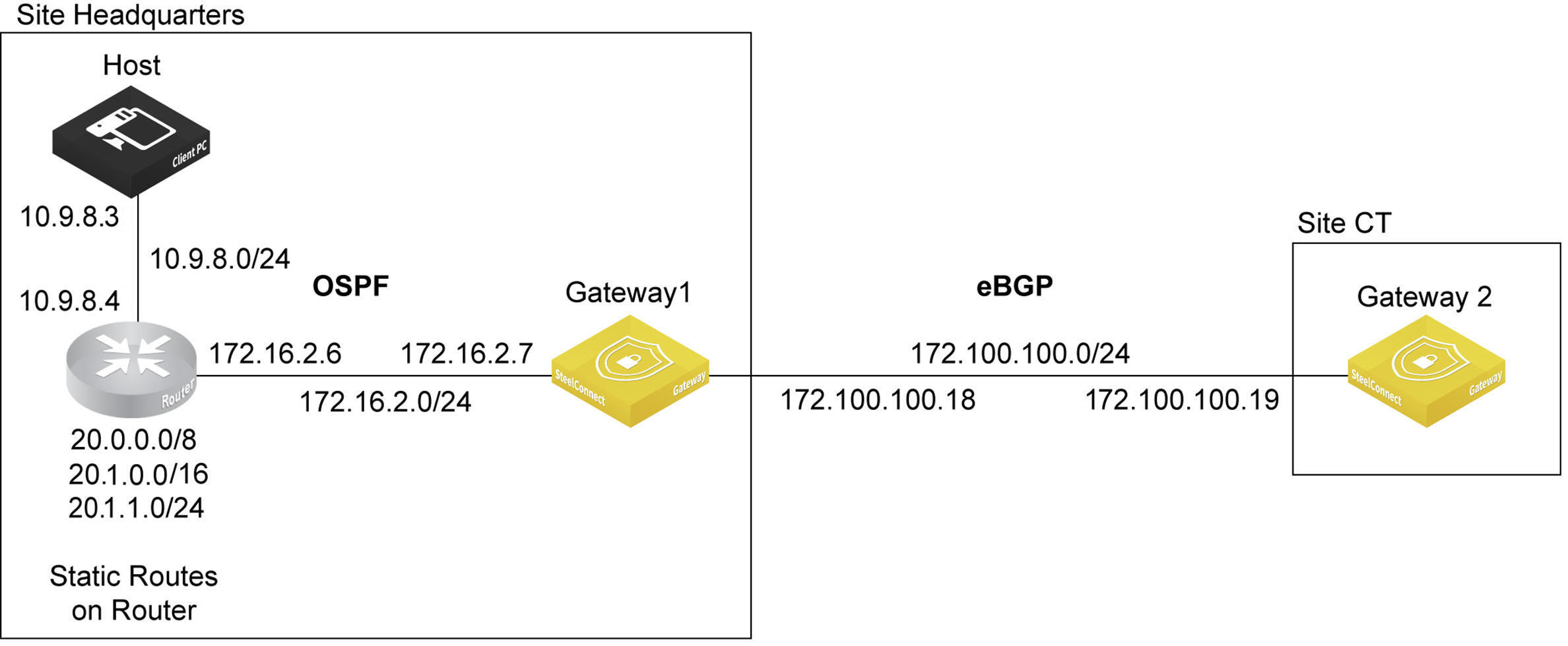
In this figure, gateway 1 advertises 0.0.0.0/0 as the default route to the LAN side router running OSPF. After learning the default route, the OSPF router is then able to reach gateway 2 (via gateway1).
Before injecting a default route, see the prerequisites in
Before you begin.
OSPF ignores any default route received from an OSPF peer.
Defining a routing policy
Each site can have one dynamic routing policy.
To define a routing policy
1. Choose Routing > Policy.
2. Click New Dynamic Routing Policy.
3. Type a name that describes the policy.
4. Select a site from the drop-down list.
5. Click Submit.
To view read-only details about the policy
•Click the Info tab.
Summarizing LAN routes via eBGP
The basic methods used to summarize LAN routes from OSPF to eBGP are:
•Enable OSPF route redistribution into eBGP.
•Configure LAN prefixes to be summarized.
These methods are described in detail in the following procedures.
To redistribute OSPF routes to an eBGP peer
1. Choose Routing > Policy.
2. Select the policy.
3. Select the BGP Profile tab.
Redistributing OSPF routes to an eBGP peer
4. Click On or Off to enable or disable redistribution of OSPF routes into WAN eBGP. By default, redistribution is disabled. This is a global option that isn’t restricted to a specific interface or BGP neighbor.
5. Click Submit.
Wait several seconds for the route redistribution to take effect.
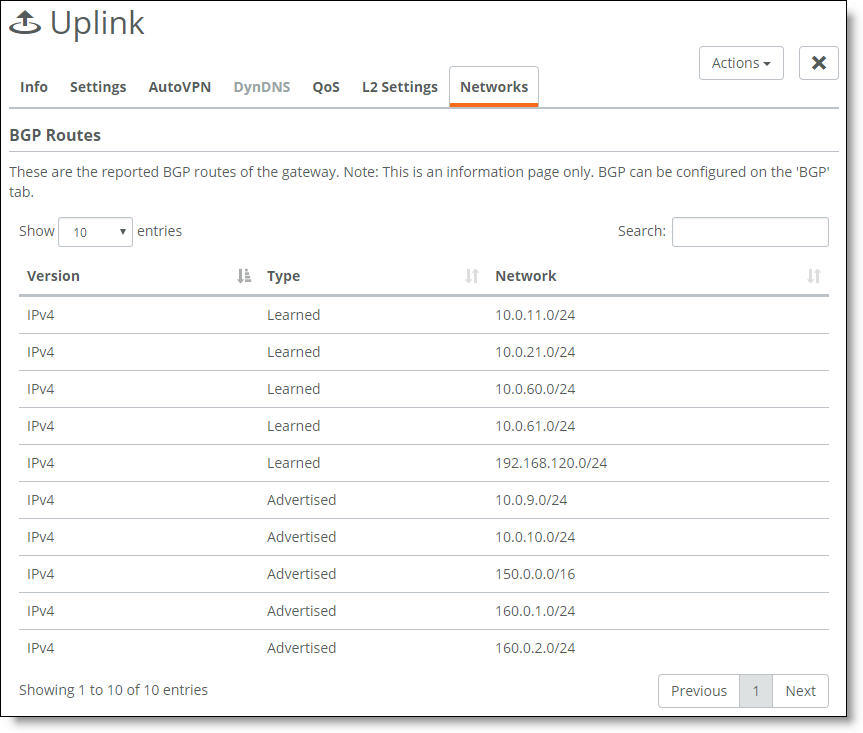
To view the route redistribution
1. Choose Network Design > Uplinks.
2. Select the site.
3. Select the Networks tab.
The redistributed OSPF networks appear as Advertised routes. On gateway appliances in other sites across the MPLS WAN, these routes will appear as Learned.
The LAN side learned and advertised routes
To add, edit, or delete LAN prefix summarization via BGP
1. Choose Routing > Policy.
2. Select the policy.
3. Select the BGP Summarization tab to add, edit, or delete LAN prefix advertisements.
If the BGP Summarization tab is unavailable, see the prerequisites in
Before you begin. In addition to the prerequisites, you must also enable Redistribute OSPF into eBGP from the BGP Profile tab.
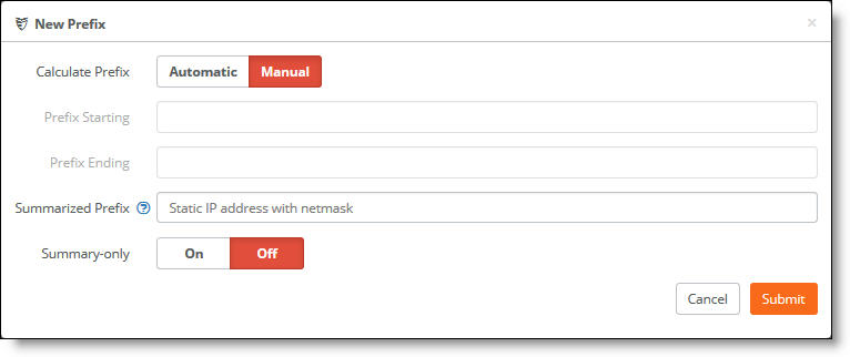
4. Click Add Prefix to add prefixes.
You can configure one or more summary addresses matching the individual addresses to advertise to a BGP peer. You can also advertise individual addresses. By default, only summary addresses are advertised.
5. Click Automatic to have SCM calculate the prefixes automatically, or click Manual to specify the prefix.
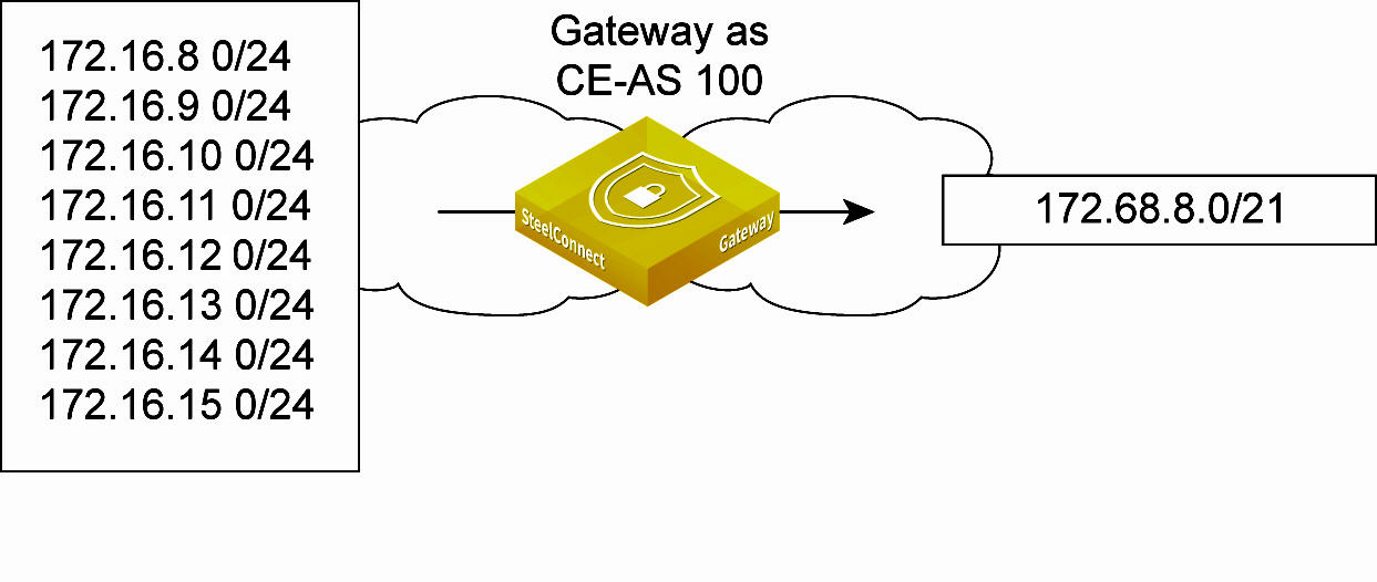
•For automatic prefix calculation, specify a starting and an ending address, and SteelConnect provides the summarized prefix. For example, entering the starting address 160.0.1.0 and the ending address 160.0.2.0 results in the automatic prefix 160.0.0.0/22.
Automatic prefix calculation
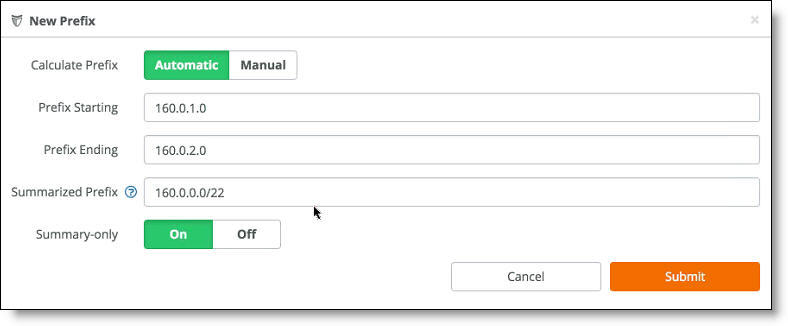
•For manual prefix calculation, after Summarized Prefix, enter a static IP address with a netmask.
6. Click Submit.
To advertise a default route
1. Choose Routing > Policy.
2. Select the policy.
3. Select the OSPF Profile tab.
Advertising a default route to the OSPF LAN
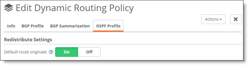
4. Click On to advertise the default route to any route not found. The default setting is off. Click Off to disable the default route injection.
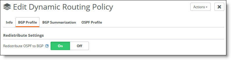
To redistribute OSPF to BGP routes
1. Choose Routing > Policy.
2. Select the policy.
3. Select the BGP Profile tab.
Redistributing OSPF to BGP routes
4. Click On to enable redistribution of OSPF to BGP routes. The default setting is off.
To distribute a summary prefix advertisement to an eBGP peer
1. Choose Routing > Policy.
2. Select the policy.
3. Select the BGP Summarization tab.
If the BGP Summarization tab is unavailable, see the prerequisites in
Before you begin. In addition to the prerequisites, you must also enable Redistribute OSPF into eBGP from the BGP Profile tab.
Advertising a summary prefix to an eBGP peer
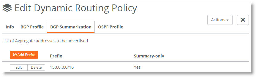
4. Verify that Yes appears under Summary-only. Yes indicates that only the summary prefix is advertised. If No appears, click Add Prefix, and after Summary Only, click On.
To distribute both summary and individual prefix advertisements to an eBGP peer
1. Choose Routing > Policy.
2. Select the policy.
3. Select the BGP Summarization tab.
If the BGP Summarization tab is unavailable, see the prerequisites in
Before you begin. In addition to the prerequisites, you must also enable Redistribute OSPF into eBGP from the BGP Profile tab.
4. Click Add Prefix.
5. After Summary Only, click Off.
Advertising individual and summary prefixes to an eBGP peer
6. Click Submit.
To delete a routing policy
1. Choose Routing > Policy.
2. Select the policy.
3. Choose Actions > Delete this policy.
ASBR routing options
SteelHead SD appliances act as full Autonomous System Boundary Routers (ASBRs) when they are located at the branch. ASBR and routing policies are supported on SteelHead SD 570-SD, 770-SD, 3070-SD, and the SDI-2030 gateway. ASBR isn’t available on the SteelConnect SDI-130, SDI-330, SDI-1030 gateways and SDI-VGW virtual gateways. The SteelHead SD User Guide provides instructions on configuring these routing options: