Designing a Network
This topic describes how to create sites, zones, WANs, and uplinks for organizations. It includes these sections:
Creating sites
A site is a physical location of one or more office buildings, a hosting center, or a cloud location that make up the organization. A site houses a SteelConnect gateway and uses a permanent DNS alias. You can create a site without an appliance and add the appliance later. When you create a site, you’re essentially configuring the location of each network you want to participate in the full-mesh VPN.
To speed up site definition for multiple sites, you can define sites in the comma-separated values (CSV) file format and import all of the definitions into SCM at once. The site definitions include the name and location of the site, the time zone, site tags, and so on.
To create a new site
1. Choose Network Design > Sites.
2. Click Add Sites.
3. Select New Site to add a single site.
4. Type a site tag, which is a name for the site: for example, NY. Don’t use spaces in the tag.
Don’t mistake the site tag with the tags mentioned in
To add tags to a site. This site tag is simply a display label that gives a name to the site. The tags you add on the Location tab are more powerful because they let you group and add structure to sites.
5. Type a site description: for example, Modesto.
6. Type the site address.
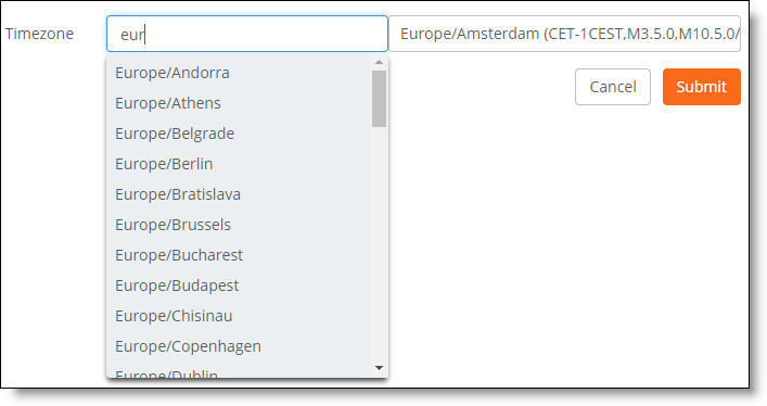
7. Select a time zone from the drop-down list.
8. Click Submit.
9. Repeat
Step 2 through
Step 8 to create additional sites one at a time: for example, factory and research lab sites.
The next task is to add tags to group sites. Tags are a powerful way to provide structure for a large number of sites and allow an additional or alternative method of grouping sites. Any sites tags that match can be grouped together. Site tags can be used to
•make creating a hub-and-spoke (Leaf mode) network topology easier.
•apply a granular firmware update policy to a group of sites.
•make bulk changes to site configurations.
To add tags to a site
1. Choose Network Design > Sites.
2. Select a site.
3. Select the Location tab.
4. After Tags, type a tag and press Enter.
A site can have none, one, or multiple tags. Repeat
Step 4 to add more tags.
With the site definitions complete, you can now configure the network zones and topology. See
AutoVPN modes.
To import multiple site definitions
1. Create a tabular data file in a spreadsheet or database that contains the site definitions and save it in the CSV format.
Source columns for bulk site creation

Include these columns in the CSV file:
•Short name - A unique short name for the site: for example, SV. Don’t include spaces.
•Long name - A descriptive name for the site: for example, Office SV.
•Tags - A comma-separated list of tags to group operations or filter sites, for example: Office, Development Sales. Use tags to provide structure for a large number of sites and allow an additional or alternative method of grouping sites. A site can have none, one, or multiple tags.
•Street address - The site’s street address.
•City - The site’s city.
•Country - A valid two-letter ISO country code.
•Time zone - The time zone associated with the site location: for example, American/New York. The time zone in the CSV file must match an entry on the Timezone list that appears on the Create Site page. To view the Timezone list, choose Network Design > Sites, click Add Site(s), and select New Site.
Valid time zones on the Create Site page
You can also define zones and uplinks in the file. If you don’t include zone and uplink definitions, you have the option of cloning preexisting zones and uplinks with site definitions after importing the file.
2. Choose Network Design > Sites.
3. Click Add Site(s) and select Bulk Site Creation.
4. Click Start: Select a CSV file and navigate to a local file.
5. Select the file and click Open.
Bulk site creation
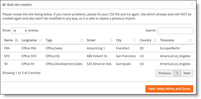
6. After the system imports the site definitions, review the site listing. To fix any problems, edit the original CSV file and reimport it. SCM will never reimport or change a site that already exists with the same short name.
7. Click Submit.
8. Click Next: Select WANs and Zones.
Optional uplink and zone selection
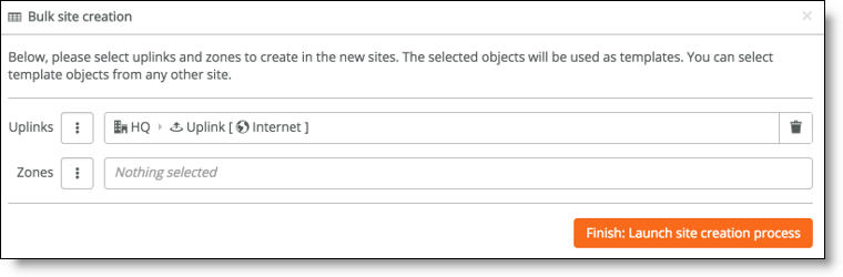
9. Optionally, select preexisting uplinks or zones to use as templates for the new sites.
When you leave the zone or uplink selection blank, the system doesn’t create any more zones or uplinks and you can add them manually later.
10. Click Finish: Launch site creation process.
The system imports the site definitions into SCM.
Bulk site creation progress
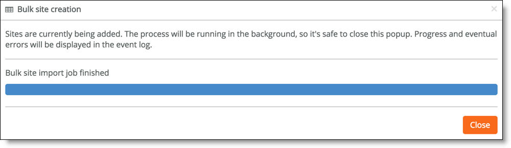
11. Click Close.
12. Select the Events tab or choose Visibility > Event Log to monitor the site creation progress in the Event log. The Event log includes any site creation errors.
Zones within a site
Zones are at the center of SteelConnect. A zone is equivalent to a Layer 2 IP segment within a site. Zones define subnets and VLANs on gateways.
Every site has at least one zone and can have multiple zones. When you create a site, SteelConnect automatically adds a default zone.
Zones can cross sites. For example, for a business application that involves a call center that requires peer-to-peer networking, you can stretch a single zone across multiple sites, providing users all over the globe with one universal security policy applied to the same IP zone.
You can add zones to any sites or any organization. A zone belongs to a site, but it can also belong to multiple sites. A site is a location like an office building, a hosting center, or a cloud location. Every site has at least one internet uplink and one local network zone.
To add a new zone to a site
1. Choose Network Design > Zones.
2. Click New Zone.
3. Select a site from the drop-down list.
All drop-down lists support type ahead. For example, in the Timezone drop-down list, you don’t need to search through the list to find Americas/New_York. Simply type New_ and you’ll see it appear in the list. This applies for any drop-down list in SCM.
4. Type a unique single word short name that describes the zone. Don’t use spaces in the name.
5. Optionally, enable the zone for guests to add some extra security and isolate the guests from other zones. Guest zones are only allowed to send traffic over to the internet.
Essentially assigning a guest zone to a site sends that traffic directly out to the internet.
6. SteelConnect configures IPv4 addresses at the zone level. A new zone can automatically use the default IPv4 address numbering specified on the Organization > Numbering Pools tab. Specify a subnet to override the default zone numbering.
Both IPv4 and IPv6 addresses come from finite pools of numbers. Don’t create a zone with a subnet the size of the full IP address pool, because doing so can exhaust the pool. After the pool is exhausted, SteelConnect is unable to create the zones with the allocated subnets.
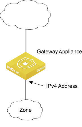
7. Specify the gateway IPv4 address for the network. A SteelConnect gateway will automatically configure itself with this IP address.
8. Select whether the default gateway configuration is automatic (the default setting) or manual. Select manual to use a third-party routing configuration or a centralized DHCP server.
For a manual gateway configuration, you must assign an IP address on the LAN side of the gateway to make the gateway a member of the zone.
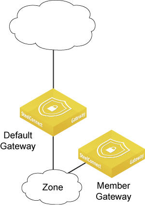
9. When there are multiple gateways in one location, select which gateway will bind to the zone as the default gateway.
10. When SCM creates new zones, it assigns the default global VLAN ID numbering specified on the Organization > Numbering pools tab. Specify a VLAN ID to override the default VLAN numbering.
11. Click Submit.
Assigning a gateway to a zone
You can assign a gateway to a zone manually or automatically. By default, SCM assigns a gateway to a zone automatically.
To manually assign a gateway to a zone
1. Choose Network Design > Zones.
2. Select the zone and then select the Gateways tab.
3. Select Manual as the default gateway configuration.
4. Click Add Assignment.
5. Select the gateway.
6. Assign the gateway IPv4 address to the LAN side of the gateway to make the gateway a zone member.
7. Click Submit.
Adding a gateway to a zone manually
Assigning more than one gateway to a zone
You can assign several gateways as members in a zone, and also you can add gateways as members to remote sites. Each gateway that becomes a member of a zone can route into the zone’s network.
To manually assign more than one gateway to a zone
1. Choose Network Design > Zones.
2. Select the zone and then select the Gateways tab.
3. Select Manual as the default gateway configuration.
4. Click Add Assignment.
5. Assign a gateway to the zone.
6. Click Submit.
Adding another gateway to a zone manually
Any gateway in a zone can act as a DHCP relay, but you must configure only one gateway as a DHCP relay per zone.
Configuring a gateway as a DHCP relay agent
You can configure a gateway as a DHCP relay agent. When a gateway is configured as a DHCP relay agent, it forwards DHCP request and reply packets between DHCP clients and DHCP servers that aren’t on the same physical subnet. The DHCP relay agent gateway doesn’t have to be the default gateway.
You can specify more than one DHCP server that a gateway relays requests to. For example, if you’re using an active/passive server cluster, and each member in the cluster has a unique IP address, you can specify both IP addresses. When two DHCP servers are specified, the gateway sends the DHCP request to both servers at the same time using the different IP addresses and only the active cluster member replies.
There is no limit to how many DHCP servers you can configure.
To configure a gateway as a DHCP relay
1. Choose Network Design > Zones.
2. Select the zone in which to locate the DHCP relay.
3. Select Gateways and select Manual.
4. Edit the existing default gateway assignment or add a new gateway assignment.
5. If the DHCP server is on, turn it off.
6. Turn on the DHCP relay.
7. Specify the IPv4 address of the DHCP server or servers to use. Separate multiple IP addresses with a comma.
8. Click Submit.
Forwarding DHCP/BOOTP requests to a DHCP server on a remote network
Gateways typically provide dynamic IP addressing to clients; however, you might want to have the gateway forward DHCP/BOOTP requests to a central IP address management server.
To forward DHCP/BOOTP requests
1. Choose Network Design > Zones.
2. Select the zone where the clients machines will connect.
3. In the LAN panel, select the Gateways tab. Set the default gateway configuration to Manual.
4. Click Edit.
5. In the Edit gateway assignment pop-up window, set DHCP/RA Server to Off.
6. Set DHCP Relay to On.
7. Type the IP address of the DHCP server in the DHCP relay address field. Separate multiple IP addresses with a comma.
8. Click Submit.
Configuring zone static routing
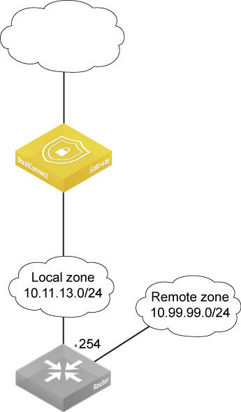
A zone that isn’t directly connected to a SteelConnect gateway is called a third-party zone. You can create a third-party zone that is reachable by other zones. After creating a third-party zone, you add a static route to make it reachable. The route includes a next hop IP address in the subnet of any of the connected networks, which is typically a third-party router.
When the uplink between the SteelConnect gateway and the third-party router (or SteelConnect gateway) are configured as BGP neighbors, the zone is advertised by the SteelConnect gateway and learned by its BGP neighbor (the third-party router or SteelConnect gateway).
For details on BGP, see
BGP.
You can create one third-party route for one zone. Multiple routes aren’t supported.
Gateway using a static route
To create a third-party zone and add a static route to reach it
1. Choose Network Design > Zones.
2. Click New Zone.
3. Select the site in which to deploy the new zone from the drop-down list.
4. Name the zone. For example, Remote Network.
5. Click Submit.
6. Select the new zone that needs to be reachable through the third-party router (shown as remote zone 10.99.99.0/24 in
Gateway using a static route).
7. Select the Gateways tab.
8. Specify the third-party zone’s primary IPv4 address.
9. Specify the third-party zone’s default gateway IP address.
IPv6 addresses are not supported.
10. Select Manual as the default gateway configuration.
11. If there’s already a gateway assigned, click Delete to remove it.
12. Click Confirm to delete the default gateway.
13. Select the Settings tab.
14. Click Add route.
15. In the From Zone field, type the zone directly connected to the SteelConnect gateway where the third-party gateway is located (shown as local zone in
Gateway using a static route).
16. In the IPv4 gateway field, type the IP address of the third-party router or gateway belonging to the local zone (shown as .254 in
Gateway using a static route).
17. Click Submit.
18. Verify that the zone appears as a third-party gateway route.
The SteelConnect gateway will now advertise the third-party zone in BGP and its BGP neighbor (the SteelConnect gateway or the third-party router) will learn the zone.
Integrating a third-party router/gateway into a zone
To use a third-party router/gateway as the default
1. Choose Network Design > Zones.
2. Select the zone and then select the Gateways tab.
3. Select Manual as the default gateway configuration.
4. If there’s already a gateway assigned, delete it.
5. Click Add assignment.
6. Assign the third-party router/gateway as a member gateway for the zone.
7. Click Submit.
8. Choose Network Design > Uplinks.
9. Select the Settings tab.
10. Select DHCP or static.
11. Select Manual as the default gateway configuration.
12. Click Submit.
Turning off outbound NAT
Network Address Translation (NAT) is enabled on all uplinks by default. You can turn off outbound NAT for deployments where:
•The gateway is behind a corporate firewall that already performs NAT.
•The network is using all public IP addresses.
•The network is internal and it routes untranslated, native addresses.
•An upstream gateway, router, or firewall will perform NAT.
To turn off outbound NAT for a zone
1. Choose Network Design > Zones.
2. Select the zone and then select the Gateways tab.
3. Change the Gateway type to manual.
4. Click Edit for the current gateway, and click On to skip outbound NAT.
To turn off outbound NAT for a site
1. Choose Network Design > Sites.
2. Select the site.
3. Select the WAN/AutoVPN tab.
4. Click On to skip outbound NAT.
To turn off outbound NAT for an uplink
1. Choose Network Design > Uplinks.
2. Select the uplink.
3. Select the Settings tab.
4. Click On to skip outbound NAT.
Adding zone details
Choose Network Design > Zones and select a zone to view more configuration possibilities.
Zone details
Defining the network and gateway IP addresses
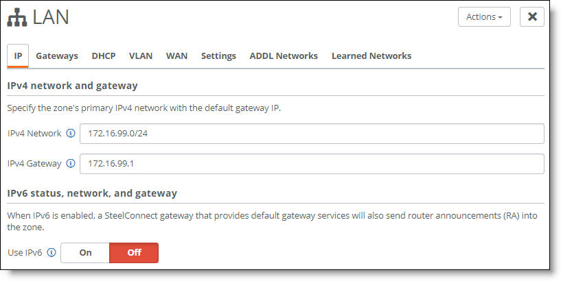
The IP tab is where you define the IPv4 or IPv6 network and gateway addresses.
By default, the gateway assumes that it is the IP gateway for the site to serve DHCP addresses. Clients on the LAN side will use it as their .1 address. Use this tab to change the default gateway IP address to any other IP address in that subnet for which it’s serving DHCP addresses.
You can also enable IPv6 to allow a gateway that provides default gateway services to also send router advertisements (RAs) for IPv6 connectivity in this zone.
To change the default gateway IP address
1. Choose Network Design > Zones and select a zone.
2. Select the IP tab.
3. Specify the zone’s primary IPv4 network.
SteelConnect does not allow 0.0.0.0/0. Use a specific IP address and subnet mask.
4. Specify the default gateway IP address.
To enable the gateway to send router advertisements for IPv6 connectivity in a zone
1. Choose Network Design > Zones and select a zone.
2. Select the IP tab.
3. Click On next to Use IPv6.
4. Specify the IPv6 network.
5. Specify the IPv6 gateway IP address for the network.
6. Click Submit.
Setting the default gateway
The Gateways tab is where you set the default gateway for the zone. By default, a SteelConnect gateway deployed in the site is automatically configured as the default gateway for this zone. The zone uses the default gateway IP addresses specified on the IP tab.
If you want to control all gateway assignments for this zone manually, or you want to use a third-party default gateway for this zone, select Manual.
To control all gateway assignments for the zone manually
1. Choose Network Design > Zones and select a zone.
2. Select the Gateways tab.
3. Select Manual next to Default Gateway Configuration.
Setting the DHCP resource for a zone
When the gateway is acting as the DHCP resource for a zone, use the settings on the DHCP tab to configure its properties and parameters. You can also use the Options field to make a specific DHCP proxy server available to the SteelConnect appliances instead of using a SteelConnect gateway as the DHCP resource.
1. Choose Network Design > Zones.
2. Select the zone.
3. Select the DHCP tab.
4. Complete these settings as needed:
Range start - First IP address available for assignment to DHCP clients.
Range end - Last IP address available for assignment to DHCP clients.
Lease time - Sets how long a gateway acting as a DHCP server waits for a zone lease renewal before invalidating its lease. The zone must renew its IP configuration data before the lease period expires or the gateway invalidates the zone’s lease and discontinues use of its current IP address. You can select a lease renewal duration time of 5 minutes to 48 hours from the drop-down list.
Options - Specify advanced configuration options for the DHCP server. Use a separate line for each configuration option.
DHCP options are not supported on SteelHead SD 570-SD, 770-SD, and 3070-SD appliances.
You can use Options to create a secure environment that prohibits direct internet access to end users or devices on an internal enterprise network. HTTP proxy support allows direct client communication and restricts direct internet access by passing all traffic bound for SCM through an explicit proxy. The DHCP server tells the SteelConnect appliance the IP address or hostname of the HTTP proxy server. The proxy is then used to connect to SCM.
To configure an HTTP proxy for a SteelConnect appliance behind a gateway
1. Choose Network Design > Zones.
2. Select the zone.
3. Select the DHCP tab.
4. In the Options field, specify the vendor code Riverbed, 42, and your HTTP proxy server IP address and port number. You must enclose the IP address or hostname and port number in quotation marks:
#option vendor:Riverbed,42,“IP address or hostname:port”
This example allows the SteelConnect appliances such as gateways, switches, and access points deployed behind a SteelConnect gateway to use a proxy for all traffic destined to SCM.
Because a gateway doesn’t necessarily receive an IP address through DHCP, setting up HTTP proxy support for a gateway behind a router requires more configuration. To configure HTTP proxy support for a gateway, you need to add the vendor code to the router in front of the gateway. When you add the Riverbed vendor code to a router, one of the uplinks will request and receive the vendor code offering, install it, and then use it.
To configure an HTTP proxy for a SteelConnect gateway behind a router
•When using the ISC DHCP server for providing DNS to a SteelConnect Gateway, specify these lines in the configuration file to set the SCM proxy address:
Option space Riverbed;
Option Riverbed.proxy code 42 = text;
Option local-encapsulation code 43 = encapsulate Riverbed;
Option Riverbed.proxy "host_addr:port_no";
The HTTP proxy needs to be available on the underlay network.
Reverse SSH tunnels don’t work with HTTP proxy support.
Assigning a VLAN ID to a zone
SCM automatically assigns a VLAN ID to a zone, even if the tags aren’t used on the wire. You can use the VLAN tab to change the VLAN ID.
Sites with SteelHead SD 570-SD, 770-SD, 3070-SD appliances and the SDI-2030 gateway aren’t automatically assigned a VLAN ID.
You can reuse the same VLAN ID in different zones in multiple sites. Two zones in the same site can’t use the same VLAN ID.
When you use the same VLAN ID in different sites, you can still import a zone from another site, unless the local destination site already uses the VLAN ID of the imported zone. When there is a conflict between the VLAN ID for the imported zone and the local destination site, the local zone takes precedence and its port, gateway assignments, and broadcast settings are used. The system disables any conflicting assignments and settings and displays an alert that the zone has not been imported.
To assign a VLAN ID to a zone
1. Choose Network Design > Zones.
2. Select the zone.
3. Select the VLAN tab.
4. Specify the VLAN tag.
5. Configure these settings as needed:
•Policy tags - Forces anything that matches a policy tag to drop into that zone. For example, you can assign certain users a policy tag, such as using tags to categorize executives into a unique zone no matter where they roam or what they plug into. You could also use a policy tag to move everyone from conference room 1 to conference room 2, or you could assign a policy tag to employees that use the same type of cubicle across the office so that they receive the same connection each time they connect to the network.
•Management zone - Click On to designate a zone as the place that access points and switches use to receive their dynamic IP addressing when DHCP is enabled. Appliances that use multizone (VLAN trunk) connectivity will use this zone for IP autoconfiguration and console communication.
•VLAN specifications - For zones associated with a trunk port on SteelHead SD models and an SDI-2030 gateway model running SteelConnect 2.11, specify the zone’s MTU and ARP-aging timeout settings. For details, see
Introducing multizone VLAN trunk mode on LAN ports in the
SteelHead SD User Guide.
Setting an internet breakout point for a zone
The WAN/AutoVPN tab is where you set the internet breakout preference for a zone. A zone’s internet breakout point overrides any breakout points previously set at the site or organization level.
You can also choose a path for each zone. For example, you could set up a testing lab zone to send its traffic over the internet. You could also set up a production zone at that site to backhaul traffic through the main data center.
Internet traffic breakout or backhaul shows an internet breakout deployment.
The WAN/AutoVPN memberships option that attached a zone to WAN is no longer supported in SteelConnect 2.10.1 and later. By default in SteelConnect 2.10.1 and later, the SD-WAN controller makes all configured zones reachable over all the WANs using AutoVPN tunnels. After upgrading to 2.10.1, zones that do not belong to any WAN/AutoVPN membership are still reachable through AutoVPN tunnels. For details, see
https://supportkb.riverbed.com/support/index?page=content&id=S32180.
To provide zone reachability over a WAN, you can configure traffic rules with a zone-based policy. For details, see
Directing traffic using traffic rules.
Zone settings
Use the Settings tab to:
•change a zone name.
•set an ICMP policy to allow or prevent ICMP traffic from entering the zone at the source. ICMP traffic is always permitted to leave the zone. This setting is useful for creating a custom ICMP policy and for allowing pings between zones to troubleshoot connectivity issues (possibly introduced by new inbound or outbound firewall rules), or to perform network testing.
Select one of these options:
–Allow all ICMP traffic to enter this zone
–Only allow ICMP ping to enter this zone
–Do not allow ICMP traffic to enter this zone. SCM blocks ICMP traffic to the specific zone at the source.
Selecting either the first option, Allow ICMP traffic to enter this zone, or the second option, Only allow ICMP ping to enter this zone, adds a rule to the top of the rules list on the Rules > Outbound/Internal rules page. Selecting the third option, Do not allow ICMP traffic to enter this zone, does not explicitly add a rule to the top of the rules list.
The ICMP policy takes precedence and overrides the inbound and outbound firewall rule settings. For details, see
Policy controls.
You can override the ICMP policy by creating a traffic rule that allows all users and devices unrestricted access to anything.
This setting is dimmed and unavailable on SteelHead SD 570-SD, 770-SD, and 3070-SD appliances because these models don’t support ICMP policies. To create a policy, you can define rules instead. For details, see
Policy controls.
•add zone static routes to networks with third-party routers when the SteelConnect gateway doesn’t have ownership of all the networks that touch it. For example, there might be a zone used as a transient network or an extension to another site connected to the LAN of that network.
Adding a secondary IPv4 network subnet to a zone
SteelConnect lets you add additional IPv4 network subnets as part of an existing zone using the ADDL Networks tab. For example, you can mix a public IPv4 network with a private one. Any subnets added become part of RouteVPN. The difference between this feature and the third-party routes described in
Configuring zone static routing is that the SteelConnect gateway can act as the gateway for this traffic.
To make these secondary network subnets reachable through a SteelConnect appliance, you must assign a gateway from the Gateways tab.
Adding a zone static route manually
Zone static routes create a route through third-party routers or gateways to remote zones. Zone static routes make the SteelConnect gateways aware of remote zone existence and how they are reached. For example, if there is a demilitarized zone (DMZ) that is separated by a firewall, you must let the remote sites know where the DMZ is located. For details, see
Configuring zone static routing.
Viewing learned networks
SteelHead SD 570-SD, 770-SD, and 3070-SD appliances and the SDI-2030 and SDI-5030 gateways provide the ability to discover subnets at the zone and site level in a branch. Local subnet discovery identifies routes that are local to a particular branch. These routes can be reached from other sites or branches using the overlay tunnels. Local subnet discovery allows you to define a set of routing criteria so that routes that match the criteria are qualified as subnets local to the branch. For details, see
Introducing local subnet discovery in the
SteelHead SD User Guide.
Deleting a zone
To delete a zone
1. Choose Network Design > Zones and select a zone.
2. From the Actions menu, choose Delete this Zone.
xLAN settings
xLAN settings are related to switch capabilities in the gateways. This setting was replaced for the most part with the autotrunk feature between SteelConnect appliances. Enable when the appliances in the site will use internal GRE tunnels to forward local zones and automatically imported remote zones. The AutoVPN appliance acts as the GRE tunnel concentrator. Enable this setting only when you need multiple zones in a site that doesn’t support VLAN operation on the wire. When xLAN is enabled, the site’s AutoVPN appliance is used as the xLAN hub.
A use case is to enable an Access Point (AP) to broadcast SSIDs on different zones when it isn’t connected to a switch that supports tagged VLANs.
For example, with xLAN enabled on a site, the access point is able to broadcast SSIDs for zone VLAN 1003 (Wi-Fi) and VLAN 1004 (Wi-Fi Guest), although it is configured in wired operation mode Singlezone.
To change the xLAN settings
1. Choose Network Design > Sites.
2. Select a site.
3. Select the xLAN tab.
4. Click On to enable or Off to disable.
You can’t configure xLAN settings on SteelHead SD 570-SD, 770-SD, and 3070-SD appliances.
DNS settings
By default, SteelConnect appliances use the IP address assigned to them using DHCP from the ISP’s DNS server. If the default DHCP-assigned server fails, the appliances use the public Google DNS servers.
You can use a corporate DNS server for all DNS resolution. You can also resolve internal IP addresses separately using DNS routing.
To change the DNS settings
1. Choose Network Design > Sites.
2. Select a site.
3. Select the DNS tab.
4. After Site DNS Servers, type the IPv4 or IPv6 DNS server primary IP address. Separate multiple IP addresses with a space.
5. Click Submit.
To view the DNS settings for an SDI-5030 gateway
1. Select the SDI-5030 gateway.
2. Choose Ports.
3. Select Port 1, the management port.
4. Select the Info/Mode tab.
The settings appear under Mode when Static IP is selected as the type.
DNS routing
You can use alternate DNS servers during the DNS resolution process. For example, you can configure internal DNS servers and forward queries to them for DNS lookup. Specifying multiple internal DNS servers localizes the queries, making DNS resolution more efficient. For example, you can split up the DNS resolution by forwarding all corporate DNS queries to an internal DNS server and forwarding all other queries to the ISP’s DNS servers. The queries resolve to one IP address on the internal network, and another on the external network, reducing the load on the corporate DNS server.
To direct DNS queries to specific internal DNS servers based on domain names
1. Choose Network Design > Sites.
2. Select a site.
3. Select the DNS tab.
4. Click New DNS route.
5. Type the domain for which you want to use an internal DNS server.
6. Type the IPv4 or IPv6 address of the target server to use to resolve the domain. Separate multiple IP addresses with a space. To bind a server to a specific source IP address, add /SRC to the IP address.
RADIUS authentication
You can configure an NPS/RADIUS server to use wireless authentication for a site. If a site doesn’t have its own server, it can use another site’s server.
You can’t configure an NPS/RADIUS server on SteelHead SD 570-SD, 770-SD, and 3070-SD appliances. Use rules instead. For details, see
Policy controls.
To configure a RADIUS server
1. Choose Network Design > Sites.
2. Select the site to configure.
3. Select the RADIUS tab.
4. Click New RADIUS Server.
5. Specify the RADIUS server IP address, and, optionally, a port.
6. Specify the shared secret using this format:
sharedsecret@<ip-address>[@<port>] (for example, sharedsecret@10.10.10.10).
7. Click Submit.
You can repeat
Step 2 through
Step 4 to add a second RADIUS server for WPA-EAP authentication if the first RADIUS server doesn’t answer within a certain time.
To set up an SSID using WPA2 Enterprise security
1. Choose Wi-Fi > SSIDs.
2. Click New SSID.
3. Select WPA2 Enterprise from the security drop-down list.
4. Click Submit.
5. Choose Wi-Fi > Broadcasts to begin broadcasting the Enterprise SSID at the applicable sites.
Forwarding inbound internet traffic to a remote server
You can allow clients on the internet to access select applications on your internal network, behind your SteelConnect gateway. To do this, you create a custom application and then create an inbound rule.
To create external to internal port forwarding on a gateway
1. Choose Applications > Custom.
2. Click Add Application.
3. Choose a name and description for the inbound application.
4. Select the application type Device from the drop-down list.
5. Select the destination server.
6. Choose a protocol such as TCP or UDP.
7. To only forward specific ports, set Limit TCP/UDP ports to On.
8. List the ports to be forwarded in the Ports text box. Specify ranges with a dash; separate several ports or ranges with a comma.
9. Click Submit.
10. Choose Rules > Inbound (NAT) and click New inbound rule.
11. Select the Application you created in the previous steps.
12. Choose one or more uplinks where you want to implement this rule. Leave the other values at their defaults.
13. Click Submit.
Creating a WAN
A WAN in SteelConnect is simply the WAN cloud that sites use to communicate with each other. It describes the type of transport available for application flows. SCM creates a default WAN. You might want to create additional WANs to enable path selection for failover or redundancy. Name your networks with words such as Primary MPLS or Internet.
To create a WAN
1. Choose Network Design > WANs.
2. Click New WAN.
3. Type the WAN name: for example, Primary or Secondary MPLS.
4. Optionally, type a longer description for the WAN and select WAN settings, described in
WAN settings.
5. Click Submit.
WAN settings
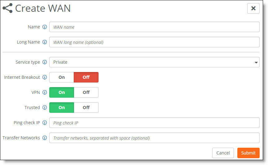
WAN settings
•Service type - Select how a custom WAN will advertise networks into the underlay: private or direct internet. Applies only to transit hubs.
Private - The SD-WAN controller will not advertise the site’s remote zones into the MPLS network.
Direct Internet - The SD-WAN controller will advertise the site’s remote zones into the MPLS network.
•Internet Breakout - Click On to break out traffic directly to the internet from this site. For a private WAN circuit without internet reachability, click Off (the default setting). When a site is selected as a breakout site, it will only use that WAN network for private WAN traffic, and will no longer use the WAN network as an internet breakout.
Traffic arriving from other sites, along with local traffic destined for the internet, will have to be routed through a different WAN network.
Internet NAT - (Appears when you enable internet breakout) Masks traffic leaving an uplink connected to an MPLS network with the uplink’s public IP address instead of using the original private source IP address. When internet NAT is on, the gateway masquerades the local packets for the entire MPLS network, including every zone.
Breakout sites - (Appears when you enable internet breakout) Select up to two sites to use as primary and secondary sites that are available as internet breakout locations. Click the search selector for a list of sites directly connected to the internet. To use a third-party site as the internet breakout site, leave the list blank and the internet breakout site configured in the Network defaults tab will be used.
When Internet Breakout is on and one or more breakout sites are configured, internet traffic is sent encrypted to the configured breakout site.
When Internet Breakout is on and no breakout site is configured, internet traffic is sent unencrypted to the WAN default gateway, because SteelConnect can't build an VPN tunnel to a unknown third-party device.
SteelConnect does not support multihop internet breakout sites.
•VPN - Click On to create an additional overlay network of VPN tunnels between internal zone-to-zone encrypted WAN traffic over noninternet uplinks. The default setting is on. Enabling VPN on a second WAN doubles the number of VPN tunnels on the gateway.
You can deploy an MPLS overlay that uses encryption and turn VPN off for another MPLS overlay.
In SteelConnect 2.10 and later, when VPN is off on the WAN, there is no underlay WAN routing between SteelConnect sites without a dynamic routing configuration. For underlay reachability to a remote SteelConnect network on the WAN, it must learn dynamically by participating in a dynamic routing protocol. You can configure dynamic routing on the WAN uplinks to establish underlay reachability to the remote SteelConnect networks via dynamic learning. For details, see
Dynamic routing overview.
When internet breakout is enabled and one or more breakout sites are configured, internet traffic is sent encrypted to the configured breakout sites. When VPN is on, zone-to-zone traffic is sent encrypted to the remote site.
When internet breakout is enabled but there isn’t a breakout site configured, internet traffic is sent unencrypted to the WAN default gateway.
•Trusted - Click On to permit all unencrypted traffic originating from a WAN to communicate into the gateway’s WAN and LAN zones, turning off the firewall. For example, enable the Trusted button to allow SteelConnect sites and legacy router sites within the WAN to communicate with each other.
By default, WANs are not trusted and the firewall is on. When this setting enabled, the firewall is off and all WAN transfer networks and eBGP learned networks are allowed to communicate into the gateway LAN zones.
A transfer network is a network on the WAN side of the gateway that isn’t part of the gateway LAN zones. For details on eBGP learned networks, see
BGP.
•Ping check IP - Add an IP address to probe for WAN availability.
If the ping fails to that IP address, the system declares all uplinks to that WAN are down. Internet uplinks perform an automatic ICMP ping check every 10 seconds. When a ping at the 10-second interval fails, it retries three times at 1-second retry intervals.
•Transfer Networks - A transfer network is a network on the WAN side of the gateway that isn’t a part of the gateway’s WAN or LAN zones. For example, a transfer network could be used for your ISP addressing or as the core of your MPLS provider that you don’t have loaded as a zone on your gateway or inside of your organization. In this example, you can either enable it as a transfer network that polls for WAN availability using an inside IP address or you can use an IP address to poll for ISP uptime.
Creating uplinks
Uplinks define how traffic is sent from the SteelConnect gateway to the various WANs to which it has been assigned. An uplink physically connects the site to a WAN. A site can have a single uplink or multiple uplinks to the same WAN and can connect to multiple WANs. You can use multiple uplinks to the same WAN for redundancy.
You need to bind an uplink to a site and a WAN.
You cannot enable multiple uplinks on the same subnet on a gateway. This is a common restriction with routers because choosing a next hop based on overlapping subnets is ambiguous.
For details on creating uplinks on an SDI-5030 data center gateway, see
Creating data center uplinks.
To create an uplink
1. Choose Network Design > Uplinks.
2. Click Add Uplink.
3. Select a site. Each uplink is site-specific and its connection type differs between sites.
4. Type the uplink name: for example, primary.
5. Select a WAN.
You can enable an uplink as a backup when no other uplinks are available. See
Step 9. Uplinks that are configured for failover must be connected to the same WAN.
6. Select how the uplink connects to the WAN:
•DHCP client (the default setting)
•Static IP
•USB cellular - Configure a USB cellular uplink to support native cellular connectivity to the internet. USB cellular uplinks are supported on SteelConnect SDI-130, SDI-130W, SDI-330, and SDI-1030 gateways that have a cellular modem plugged into the USB port. You can configure a USB cellular uplink as a primary or backup uplink.
Make sure to plug the modem all the way into the USB port to use this uplink. The gateways support subscriber identity module (SIM) access point names (APNs) and personal identification numbers (PINs) for the cellular modems.
Specify the SIM APN and PIN, and skip to
Step 9.
The SteelHead SD 570-SD, 770-SD, and 3070-SD appliances don’t support USB cellular uplinks.
•DSL/PPPoE - Configure a DSL physical layer that uses the Point-to-Point Protocol over Ethernet (PPPoE) credentials on the gateway so it can authenticate and tunnel with the internet service provider. This typically means that the customer enters a username and password provided by the ISP to use the last-mile link from the customer premises to the ISP. The gateway then connects to the internet using NAT and routes traffic between the configured zones and the internet.
•DSL/PPPoA/PPTP
Most DSL lines have a forced reconnect imposed by the ISP, typically in a 24-hour interval. You can proactively select the disconnect and reconnect time to control when the disconnect occurs.
For example, if you switched your modem on for the first time during business hours, you’ll be stuck with a reconnect during business hours, every 24 hours, until you disconnect proactively outside of business hours. You can use the Time for PPP-reconnect setting to automate disconnects at a specified time.
To reconnect PPP uplinks at a certain time of day, select a 15-minute interval from the Time for PPP-reconnect drop-down list.
The SteelHead SD 570-SD, 770-SD, and 3070-SD appliances don’t support the DSL/PPPoE or DSL/PPPoA settings for uplinks.
The PPPoA setting is not available with USB cellular uplinks.
7. For an uplink using a static IP address, complete these fields (either IPv4 or IPv6):
•Specify a static IPv4 address. When creating an uplink to a private network, you must specify the IPv4 address with a /32 netmask.
•Specify a static IPv4 gateway.
or
•Specify a static IPv6 address.
•Specify a static IPv6 gateway.
8. Optionally, specify a VLAN tag ID (1 through 4049). Use caution and specify only when required under special circumstances. When you specify a VLAN tag, connectivity to uplinks without a VLAN tag or uplinks that use a different VLAN tag is lost.
The VLAN tag ID is unavailable on SteelHead SD 570-SD, 770-SD, and 3070-SD appliances because they don’t support VLAN tags for uplinks.
9. Optionally, you can demote the uplink as a backup for use only when no other uplinks are available. This setting applies to two uplinks connected to the same WAN. When there is only one uplink and it’s set to backup only, it will be used until there is another uplink in the same WAN that is always active.
The SD-WAN controller establishes tunnels on both the active and backup uplinks.
To monitor the active and backup uplinks, the SD-WAN controller probes for a response from the uplinks every 10 seconds. When an uplink does not respond, SteelConnect considers the uplink to be down and the backup uplink becomes active immediately. The backup tunnel uplink responds to the probe request even when it’s inactive and the active tunnel is handling traffic flows.
Probing both the active and backup uplinks every 10 seconds for a response minimizes the failover time from the active to backup uplink in the event the active uplink goes down. However, the probing incurs some CPU overhead and can consume uplink bandwidth. The probe packet size is 216 bytes. If the probe sends a request but does not receive a response, the controller sends four more probes every second.
The SteelHead SD 570-SD, 770-SD, and 3070-SD appliances and the SDI-2030 gateway don’t support the backup setting for uplinks. The SDI-5030 gateway uplinks are always active by design.
10. Click Submit.
SCM sends the configuration to the gateway.
For a USB cellular uplink, the next task is to configure a USB port. For details, see
Port settings and status.
To turn an uplink off
1. Choose Network Design > Uplinks.
2. Next to the uplink, under Operation, click Off.
When you turn an uplink off, the backup uplink becomes active and maintains connectivity to the WAN. The uplink interface goes down but the uplink configuration remains in place. After the uplink is turned back on, existing and new traffic will use the uplink again with its previous configuration.
If you attempt to turn off the only uplink connection to an appliance, a warning tells you that you can't turn it off because doing so will cause a loss of connectivity.
Selecting an uplink priority
You can set an AutoVPN priority for uplinks connected to the same WAN that determines the order in which they are used. For example, when you create two uplinks and set the first uplink to high priority and set the other to normal, SCM creates a tunnel for the uplink with the highest priority.
If something happens to the high-priority tunnel, SCM reestablishes the tunnel through the uplink with the next highest priority.
When you set the same priority for both uplinks, SCM creates a tunnel for each one based on the source and destination.
To set an uplink priority
1. Choose Network Design > Uplinks.
2. Select an uplink.
3. Under AutoVPN priority, select one of these options from the drop-down list:
•Don’t use this uplink for AutoVPN - Disables AutoVPN use for the uplink.
•Low - Sets the uplink to the lowest priority.
•Normal - Sets the uplink to the normal priority.
•High - Sets the uplink to the highest priority.
4. Click Submit.
Turning off AutoVPN for an uplink
At times you might want to disable AutoVPN for an uplink. For example, you can turn AutoVPN off to bring a tunnel down for troubleshooting tunnel connectivity.
To turn off AutoVPN for an uplink
1. Choose Network Design > Uplinks.
2. Select an uplink.
3. Under AutoVPN priority, select Don’t use this uplink for AutoVPN.
4. Click Submit.
Creating an uplink for a single router to an MPLS network
To set up a VPN over the MPLS network as shown in
One router connecting to MPLS, configure the uplink of the gateway to propagate the internal IP address that the remote sites use as the endpoint target for the AutoVPN tunnel. By default, SCM uses the external IP address facing the internet.
SCM activates AutoVPN only for uplinks connecting to WANs using the internet and skips other interface types.
To configure an uplink to use an internal interface
1. Choose Network Design > Uplinks.
2. Select the uplink.
3. Select AutoVPN.
4. Select Internal Interface IPv4.
5. Click Submit.
Viewing uplink status
You can view uplink status on the Network Design > Uplinks page, by looking at the event log, or by choosing Health Check > Uplink Health.
To check uplink status on the Uplinks page
1. Choose Network Design > Uplinks.
2. Select the uplink.
The status appears on the Uplinks page and the Info tab:
•Online - The uplink is up and has reachability to the next-hop router.
•Offline - The uplink is down and does not have reachability to the next-hop router.
•Unknown - The appliance is unable to query the next-hop router for reachability.
On a SteelHead SD 570-SD, 770-SD, or 3070-SD appliance, when the routing virtual machine (RVM) in SteelOS goes down, the system still maintains the last populated Longest Prefix Match (LPM) and Address Resolution Protocol (ARP) keys. The data plane continues to function, but the uplink liveliness detector is momentarily suspended and temporarily reports uplinks with an unknown status. When the RVM comes back up, the uplink status returns to online. Depending on how the routing converges and how long it takes to populate the ARP table, there might be a brief disruption in traffic flow. This is expected behavior. For details on the SteelOS architecture, see the SteelHead SD Installation Guide.
Configuring a direct alternate hub
A direct alternate hub configuration provides a solid failover and communication method between branch sites for these use cases:
•SteelConnect branches moving traffic from one type of WAN to another. For example, traffic moving from one MPLS carrier to another, or deployments that are integrating internet-only sites with existing dual MPLS-internet sites where traffic is moving between these disjoint WANs (internet and MPLS) for end-to-end connectivity.
•SteelConnect branches in a hybrid network that are integrating internet-only branch sites with existing MPLS-only branch sites. The alternate hub configuration ensures that all interbranch communications (such as VoIP calls) continue to work despite the diversity of (or failure of one of) the WANs. The alternate hub routes traffic when the direct path between branch sites in a hybrid network is down by providing a next-hop site for routing traffic and communication.
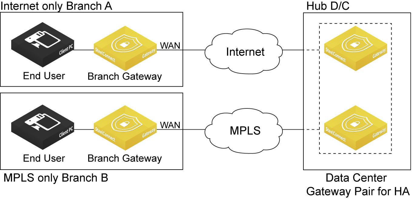
Disjoint WANs connected through an alternate hub shows two SteelConnect branches that would typically not be able to connect to each other over the disjoint WANs (internet and MPLS) without a common hub to act as a transit node between the branches. After configuring the data center as an alternate hub, traffic can move between the branches connected to the disjoint WANs through the common hub.
Disjoint WANs connected through an alternate hub
Hybrid WANs using an alternate hub for redundancy shows the data center hub sending traffic between the internet-only and dual-connected (internet and MPLS) SteelConnect branch sites. If the direct AutoVPN path fails, the hub redirects the traffic over a backup path to ensure uninterrupted connectivity between the branch sites.
Hybrid WANs using an alternate hub for redundancy
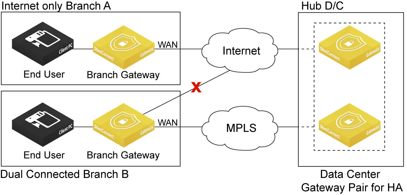
In
Hybrid WANs using an alternate hub for redundancy, because Hub D/C is the transit between branch A and branch B, both A and B need to configure Hub D/C as the alternate hub.
In both the disjoint and hybrid WAN deployments with an alternate hub, TCP, UDP, ICMP, and other IP traffic can move between the remote sites in both directions and all SteelConnect services can be applied to the traffic.
Alternate hub requirements
You can configure one alternate hub. Before configuring an alternate hub, check these requirements.
•The alternate hub must be a nonleaf site.
•The alternate hub must have connectivity to at least one WAN in common with the branch sites.
•The common WAN has to be an internet or an encryption-enabled MPLS WAN.
To configure an alternate hub
1. Choose Network Design > Sites.
2. Select a site.
3. Select the WAN/AutoVPN tab.
Alternate, nonleaf hub configuration
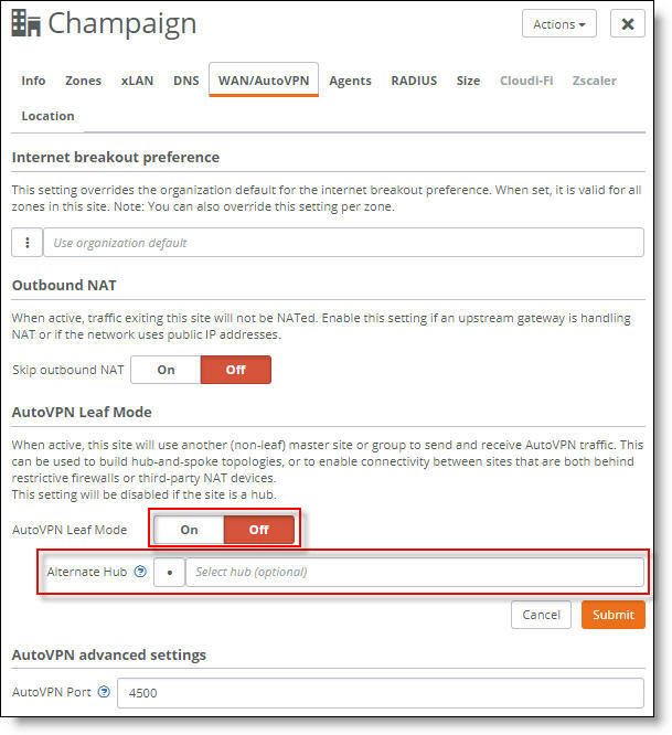
4. Turn off AutoVPN Leaf Mode.
5. After Alternate Hub, click the Search selector and select an alternate hub from the list. The list includes only those hubs that are nonleaf sites and share an uplink to a common internet or encrypted WAN.
6. Click Submit.