SteelConnect Ports
This topic describes ports and port settings in SteelConnect. It includes these sections:
Port overview
A SteelConnect port on an appliance is an Ethernet interface used either for WAN or LAN. The number of physical interfaces supported for each branch gateway model are:
•SDI-130: 2
•SDI-330: 2
•SDI-1030: 12
The SDI-130 and SDI-330 gateways have two physical interfaces that can be used as uplink interfaces. There are also eight switch ports on the 130 and 330 that cannot be used as uplink interfaces, but only as zone or multizone interfaces.
On the SDI-1030 gateway, four of the 12 ports are Small Form-factor Pluggable (SFP+) ports. The SFP+ ports do not support 1GbE via SFP. The ports operate only in 10GbE mode.
After attaching a modem to one of the interfaces on an SDI-130 or SDI-330 gateway, you can only support two WANs on that device. For example, you can support MPLS on interface 1 and support internet through an LTE modem on interface 2.
Virtual gateway ports
SDI-VGW virtual gateways require a minimum of two ports: one LAN and one WAN. The default configuration ships with three ports, but you can add more by modifying the VM configuration outside of SCM. Adding more WAN ports increases your uplink options.
The number of virtual gateway ports supported depends on how many the hypervisor allows. For example, ESXi 5.5 supports ten ports for the SDI-VGW virtual gateway.
The virtual gateway ports are labeled as LAN on the Ports page.
Port settings and status
You can use the Ports page to:
•set the port mode that determines how the port functions: singlezone or multizone. You can also set the port mode to uplink for individual uplinks or mirrored uplink for branch gateway high-availability configurations.
On SDI-130 and SDI-330 gateways, LAN ports cannot be configured as uplinks and WAN ports cannot be configured in singlezone or multizone port mode.
•enable native VLAN support.
•set autotrunking on or off. Enable autotrunking to interconnect and form a trunk when more than one zone is mapped across it. For example, as soon as you connect a SteelConnect access point to a SteelConnect switch, they negotiate a trunk automatically. The access point will have a trunk port configured with all zones for that site.
By default, autotrunking is enabled.
•enable 802.1x authentication for network access control. When autotrunking is enabled, 802.1x authentication is disabled and vice versa.
•view the MAC addresses for which traffic is being forwarded through the port.
•view the raw port counters for advanced debugging.
•create a label that describes the patch panel socket or wall socket to which the port is connected.
For details on a SteelHead SD primary port configuration, see
Introducing SteelHead SD in the
SteelHead SD User Guide.
For details on a configuring a management port on an SDI-5030 data center gateway, see
Configuring ports.
To view ports
•Choose Appliances > Ports.
Ports page
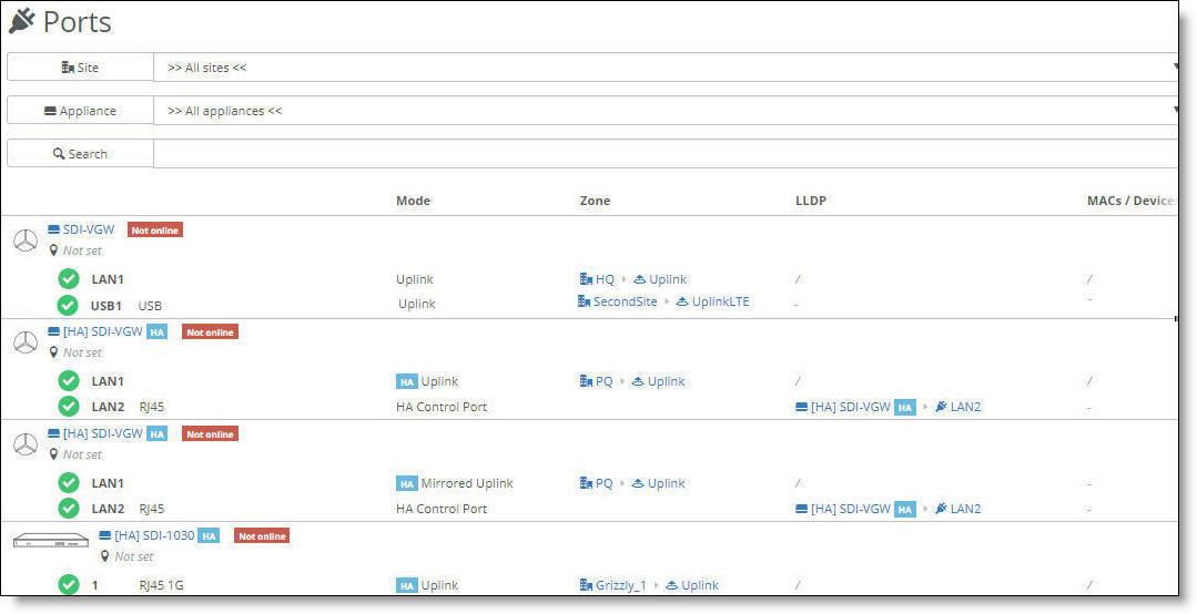
SteelConnect Manager displays the ports and port status, their operation mode, zones, and more.
The icons in front of the port indicate status:
Icon | Status |
|
The link is up.
|
|
The link is down.
|
|
The port is in a blocking state because either the Spanning Tree Protocol (STP) is discarding packets or there is an 802.1x authentication failure.
|
To view more port details
1. Select a port.
2. Select the Info/Mode tab.
Setting the port mode
The port mode determines how the port functions. The port can use singlezone or multizone mode.
You can also set the port mode to uplink for individual uplinks or mirrored uplink for branch gateway high-availability configurations.
Configuring the uplink mode
To set the port mode to uplink
1. Select a port.
2. Select the Info/Mode tab.
3. Next to Port mode, select Uplink.
4. Select the uplink. On a USB port, uplink is the only available mode.
For details on selecting the Uplink and Mirrored Uplink port mode options for branch HA partners, see
Port configuration.
5. Click Submit.
Port mode limitations
These limitations apply to specific gateways and appliances:
•On SDI-130 and SDI-330 gateways, LAN ports cannot be configured as uplinks and WAN ports cannot be configured as singlezone or multizone ports.
•The SteelHead SD 570-SD, 770-SD, and 3070-SD appliances do not support dedicated ports or mirrored uplinks. For details on defining a trunk port, see
Defining trunk mode on ports in the
SteelHead SD User Guide.
•The SteelHead SD 570-SD, 770-SD, and 3070-SD appliances do not support the uplink USB port mode.
Checking the connection status for a USB port
On the Info/Mode tab for a USB port, the connection status displays whether the LTE modem is connected to the gateway. When the connection status reports that the modem is connected to the appliance, but the link status is down, it means that something went wrong when the modem tried to connect to the cellular network. For details, you can view the event log for the modem states during the connection process.
Hot plugging an LTE modem in an SDI-130 gateway over an AWG 28 USB cable can cause a significant voltage drop (~2V). The voltage drop might cause the SDI-130 to reboot. We recommend that you don’t hot plug a USB modem, but if it is necessary, use an AWG 26 or thicker cable with a lower resistance.
To view events
•Select the Events tab or choose Visibility > Event Log.
LTE modem event log states
Modem event | Meaning |
PIN invalid | The PIN that the user set up is invalid. |
PIN locked | An invalid PIN has been entered for the second time and the appliance has locked the PIN for the subscriber identity module (SIM). |
Registered | The modem was registered on the network. |
No network | The modem was not registered on the network. |
Connected | The connection to the wireless distribution service was successful. |
Start network failed | The connection to the wireless distribution service failed. |
Configured | The Layer 3 configuration was successful. |
IP setup failed | The Layer 3 configuration was unsuccessful. |
To disable autotrunking
1. Select a port.
2. Select the Advanced tab.
3. Next to AutoTrunking, click Off.
4. Click Submit.
To override a port’s default MAC address
1. Select a port.
2. Select the Advanced tab.
3. Next to Virtual MAC, specify a MAC address.
4. Click Submit.
To provide a socket label to the port
1. Select a port.
2. Select the Info/Mode tab.
3. After Port Description, type a reference to the patch panel socket or wall socket that this port is connected to. The maximum label can be 16 characters.
4. Click Submit.
Configuring a singlezone port
Selecting singlezone is the equivalent of setting the port as an Access port where the VLAN traffic or traffic is untagged. The port will drop the traffic should it ingress as tagged (or with a VLAN tag).
To set the port mode to a singlezone
1. Select a port.
2. Select the Info/Mode tab.
3. Next to Port mode, select Singlezone.
4. Select the zone to associate with the port’s VLAN ID. The zone is assigned to only one VLAN.
When untagged frames ingress a singlezone port, the switch forwards the frames internally to all of the singlezone ports in the same zone, and also tags the frames with the zone’s VLAN ID and forwards them to the multizone ports.
5. Click Submit.
Configuring a multizone port
A multizone port is synonymous with a trunk port. A multizone port can carry traffic from multiple zones (VLANs); it expects to receive tagged traffic. The switching fabric will then strip the tag and forward that traffic to any other ports that are appropriate to that tag.
By default, a port is automatically configured for multizone when it’s connected to another SteelConnect appliance. For example, as soon as you connect a SteelConnect access point to a SteelConnect switch, they negotiate a trunk. The access point will have a trunk port configured with all zones configured for that site.
For each multizone port (trunk) a native VLAN can be configured to allow untagged frames to travel over a trunk along with other tagged frames. For details, see
Native VLAN support.
The SteelHead SD 570-SD, 770-SD, and 3070-SD appliances support the multizone port option on the LAN side.
To set the port mode to multizone
1. Select a port.
2. Select the Info/Mode tab.
3. Next to Port mode, select Multizone (VLAN tagged).
The port maintains the 802.1q tags in the packet and forwards on the trunk port.
Any packets egressing the port will be tagged with the zone’s VLAN ID.
By default, multizone ports do not have an assigned zone.
4. Click Submit.
Native VLAN support
This section describes how to configure native VLAN support for a Xirrus access point or other supported network device that requires native VLAN functionality. Native VLAN allows an appliance to accept both untagged and tagged traffic over a multizone port connection. By default, a multizone port expects to receive tagged traffic.
Native VLAN support is configurable on the SDI-130 and SDI-330 gateways and the S12, S24, and S48 switches.
By default, without configuring native VLAN, a port configured for multizone drops any untagged traffic.
Xirrus access point use case
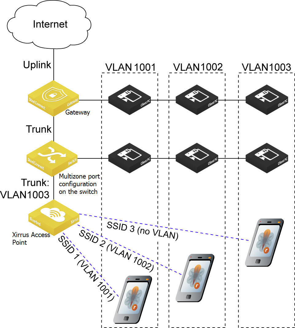
Xirrus access point and SDI gateway integration shows a deployment where clients on the access point are placed in the same VLAN with clients on the switch or the gateway. This deployment demonstrates how to configure a guest Wi-Fi network and an internal corporate network for full access, using VLAN 1001 for guests and VLAN 1002 for full access.
Typically when there is a wired connection for guests, they plug into the switch or gateway on ports with VLAN 1001, and employees plug into VLAN 1002 for full access. However, when employees need to access the internal network from a conference room using Wi-Fi, they must use VLAN 1002. To configure this, you create an internal Riverbed SSID (Wi-Fi) for VLAN 1002. Next, to grant guests access to the wireless network in VLAN 1001, you create another SSID for Riverbed guests.
Xirrus access points can accommodate this separation based on VLAN tag, but they require their management traffic to arrive untagged in order to connect to the internet. This means the tagged frames with VLAN 1001 and VLAN 1002 travel on the trunk connection between the access point and switch, but the VLAN 1003 management traffic needs to travel untagged. To achieve this, you need to set native VLAN 1003 for a multizone port.
To configure the Xirrus access point to receive both tagged traffic and untagged management traffic, you place the management traffic onto the native VLAN using a multizone port connection (configured on the switch in the deployment shown in
Xirrus access point and SDI gateway integration). The native VLAN supports both the tagged SSID-associated client traffic and the untagged management traffic.
The port still works as a multizone port in that it sends and receives tagged traffic; however, if it receives untagged traffic, it will accept it and then tag it with the VLAN ID associated with the zone. The port sends a packet down to the access point or the switch that has the source VLAN ID associated with the zone.
Xirrus access point and SDI gateway integration
The native VLAN settings allow an access point or other device to successfully decode the untagged frames in the management zone, obtain an IP address, and connect to the internet.
If autotrunking is enabled (the default), it automatically configures the ports between the two Riverbed appliances as multizone ports with no native VLAN assigned. While a trunk port link between two Riverbed appliances might successfully establish a connection with mismatched native VLANs, we strongly recommend that you configure both sides of the link identically. Mismatched native VLANs can generate security flaws and leave the network open to security risks.
To integrate a Xirrus access point with SCM
1. Choose Organization and select the Wi-Fi Manager tab.
Each SCM organization needs to be connected to an XMS-Cloud domain before you can manage the XR, X2, XD, XH, and XA access points through SCM for an organization. A domain is the XMS-Cloud equivalent of an SCM organization.
Connect the organization to the Wi-Fi Manager
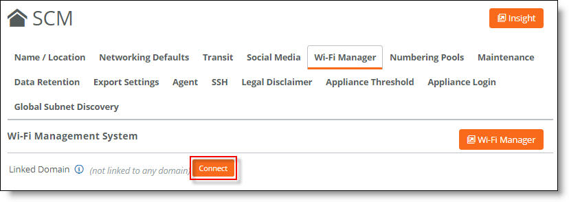
2. Click Connect.
A dialog informs you that any legacy access point configurations will be replaced with the Xirrus access point configuration.
3. Click Confirm.
4. Enter your XMS-Cloud username and password.
5. Click Submit.
6. In SCM, if you have not done so already, choose Network Design > Sites and create one or more sites.
Because you have connected your SCM organization to your XMS-Cloud account, the Xirrus access points that are associated to your XMS-Cloud account appear under Appliances.
You must have at least one Xirrus access point with its location set to a site for SCM to automatically configure your XMS-Cloud account. To set a site as a location, choose Appliances > Overview, select the Xirrus access point, select the Location tab, and select a site where the access point is deployed from the Site drop-down menu.
7. Create zones for a site that represent the VLANs. The site must include a management zone, which is created by default.
To configure a management zone manually, select the zone, select the VLAN tab, and turn on the management zone. For details, see
Zones within a site.
8. If your Xirrus access point is connected to a SteelConnect gateway or switch, choose Appliances > Ports, select the appropriate gateway or switch, and select the port that the Xirrus AP is connected to.
Native VLAN is supported on SDI-130 and SDI-330 gateways, and S12, S24, and S48 switches.
9. Select the Info/Mode tab.
10. Set the Port Mode to Multizone (VLAN tagged).
Multizone (VLAN tagged) port configuration
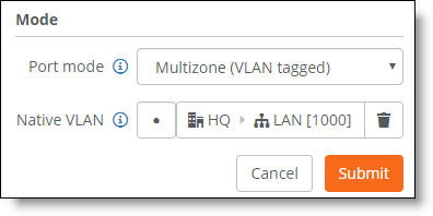
11. For Native VLAN, select the LAN zone to use as the native VLAN. The zone will carry the management traffic for the connected Xirrus AP.
Traffic belonging to the selected LAN zone will be forwarded untagged and classified into the native VLAN. All other traffic will be forwarded tagged.
12. Click Submit.
13. Choose Wi-Fi > SSIDs to create SSIDs that you want to be part of your XMS-Cloud Profile.
14. Click New SSID.
15. Enter the name of the SSID.
16. Select the encryption and authentication method for the SSID.
17. Enter a password that users must enter to gain access to this SSID. The password must either be 8 to 63 ASCII characters or 8 to 64 hexadecimal characters.
18. Click Submit.
19. Choose Wi-Fi > Broadcasts to create a broadcast that will advertise the SSIDs you created in
Step 13.
20. Click New Broadcast.
Broadcast to advertise the SSID
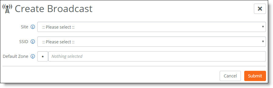
21. Select the desired site and SSID.
22. Select the default zone for this broadcast. If you want client traffic for the broadcast to be untagged and use the port’s native VLAN, leave Default Zone blank.
23. Click Submit.
After completing these SCM configuration steps, when you log in to your XMS-Cloud account (also known as your tenant), the account will be in a read-only state to prevent edits outside of SCM.
To view the SSIDs and access points in XMS-Cloud
1. Log in to XMS-Cloud and select Profiles to view the profile that SCM automatically created. The profile has the same name as the SCM site.
2. Select that profile.
3. Select SSIDs to view the SSIDs created in SCM.
4. Select the Access Points tab to view the Xirrus access points added to this profile.
Enabling port-based network access control
To better protect a network from unauthorized systems and users, you can enforce access control on the gateways by enabling port-based authentication. Port-based network access control, or Layer 2 access control, protects the network from rogue and potentially malicious users by preventing access to network resources until a client is authorized using 802.1x.
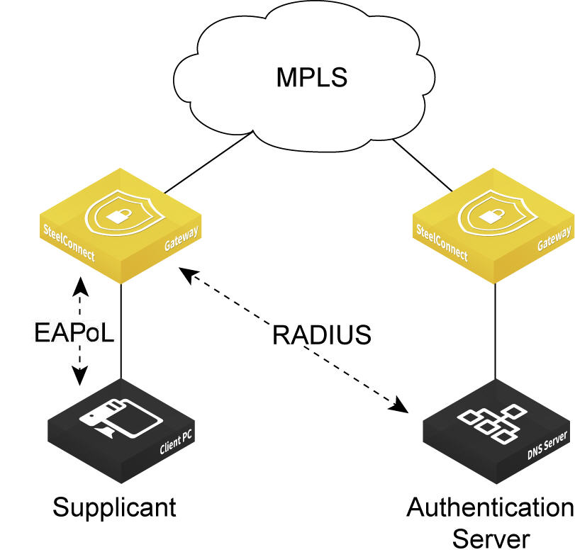
SDI-130 and SDI-330 gateways can use 802.1x authentication between a client, known as a supplicant, and a RADIUS server using an Extensible Authentication Protocol (EAP) method. The RADIUS server is responsible for authenticating users. The gateway acts as an authenticator between the supplicant and the RADIUS server. The supplicant is a device that wants to connect to the network. Until the supplicant’s identity has been validated and authorized by the RADIUS server, the gateway prevents access to the network.
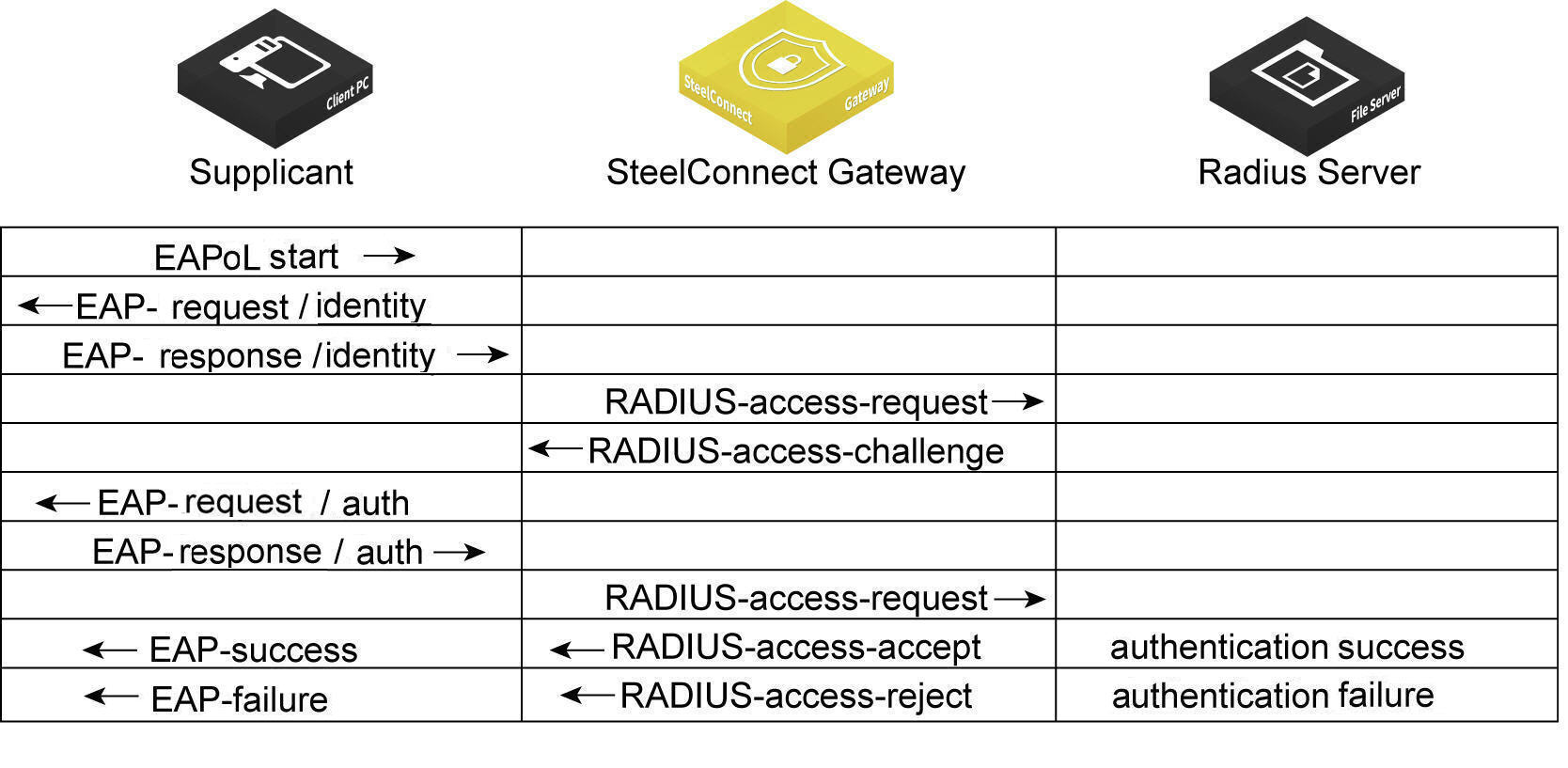
What is the gateway’s role in the authentication process?
The gateway performs EAP over LAN (EAPoL) exchanges with the supplicant and converts these exchanges to RADIUS access-request messages. The access-request messages are sent to the RADIUS server’s IP address without changing anything. The RADIUS server verifies the supplicant’s credentials and transmits a response back to the gateway acting as the authenticator. After the gateway receives a RADIUS access-accept message from the RADIUS server, it allows the supplicant access to the network.
802.1x authentication process
Topologies
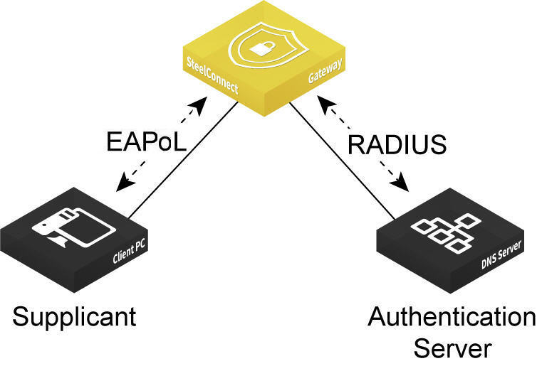
The gateway must be able to reach the RADIUS authentication server using one of these methods:
•Through the LAN using the same or different VLAN zone.
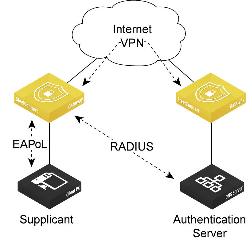
•Over the VPN.
•Over the MPLS.
Port-based authentication through the LAN
Port-based authentication through the VPN
Port-based authentication through the MPLS
To enable 802.1x authentication
2. Choose Appliances > Ports.
3. Select the appliance.
4. Select the port on which to enable 802.1x. The port must use singlezone mode. Multizone mode is not supported.
5. Select the Advanced tab.
6. Next to 802.1X, click On. By default, 802.1x authentication is disabled.
Enabling 802.1x authentication on a port
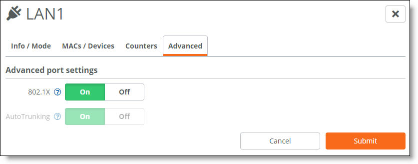
The system dims the autotrunking feature because autotrunking and 802.1x authentication are mutually exclusive.
7. Click Submit.
Give a client a couple of seconds to connect to the gateway. If necessary, enter the security credentials on the client to allow it to use network authentication at the port.
To verify 802.1x authentication
•Select the Info/Mode tab.
When the port is using 802.1x authentication, “Authenticated” appears next to 802.1X.
The Info/Mode tab reports any changes in the link state. For example, if the cable to the client is unplugged, “Unauthenticated” appears next to 802.1X.
