Physical In-Path Deployments
This chapter describes a physical in-path SteelHead deployment. This chapter includes the following sections:
This chapter requires that you be familiar with:
• Hot Standby Router Protocol (HSRP)
• Virtual Router Redundancy Protocol (VRRP)
• Gateway Load Balancing Protocol (GLBP)
Overview of In-Path Deployment
In a physical in-path SteelHead deployment, a SteelHead LAN interface connects to a LAN-side device (typically a switch), and a corresponding SteelHead WAN interface connects to a WAN connecting device (typically a router). This allows the SteelHead to detect all traffic flowing to and from the WAN and to perform optimization.
Depending on the SteelHead model and its hardware configuration, you can use multiple pairs of WAN and LAN interfaces simultaneously, and you can connect them to multiple switches and routers.
Figure: Single Subnet, Physical In-Path Deployment shows the simplest type of physical in-path SteelHead deployment.
Figure: Single Subnet, Physical In-Path Deployment
Most SteelHead deployments are physical in-path deployments. Physical in-path configurations are the easiest to deploy and do not require ongoing maintenance as other configurations do (such as virtual in-path configurations: WCCP, PBR, and Layer-4 redirection).
For networks that contain firewalls or tunnels (VPN, GRE, IPSec transport mode) between SteelHeads and require manual tuning of the MTU values, see
MTU Sizing.
You must manually configure the IP address for any optimization interface, including the primary interface, in an out-of-path deployment. DHCP is not supported.
Logical In-Path Interface
All SteelHeads ship with at least one pair of ports that are used for in-path deployments. This pair of ports forms the logical in-path interface. The logical in-path interface acts as an independent, two-port bridge, with its own IP address. This section includes the following topics:
Figure: Logical In-Path Interface in a Single Subnet In-Path Deployment shows the SteelHead logical in-path interface and how it is physically connected to network devices in a single subnet, in-path deployment.
Figure: Logical In-Path Interface in a Single Subnet In-Path Deployment
The simplest in-path SteelHead has two IP addresses:
• Primary - Used for system management, RiOS data store synchronization, and SNMP.
• Inpath0_0 - Used for optimized data transmission.
Several types of network interface cards (bypass cards) are available for SteelHeads. The desktop SteelHeads have network bypass functionality built in. With 1U and 3U systems, you can choose the type of bypass card. SteelHeads can have both copper and fiber Ethernet bypass cards.
For information about bypass cards, see the Network and Storage Card Installation Guide on the Riverbed Support site.
In-Path IP Address Selection
An IP address is required for each SteelHead in-path interface. When using correct addressing or port transparency, the IP address must be reachable by remote SteelHeads for optimization to occur.
In some environments, the link between the switch and the router might reside in a subnet that has no available IP address. You can use the following solutions to accommodate the IP address requirement:
• Create a secondary interface, with a new subnet and IP address on the router or switch, and pull the SteelHead in-path interface IP address from the new subnet.
• Create a new 802.1Q VLAN interface and subnet on the router and switch link, and pull the SteelHead in-path interface IP address from the new subnet. This solution also requires entering the appropriate in-path VLAN tag on the SteelHead.
Note: You must manually configure the in-path IP address for in-path deployments. DHCP is not supported.
With RiOS 5.0.x or later, you can deploy SteelHeads so that the in-path interface IP address is not actually used. This deployment option can be useful for integrating with certain network configurations, such as NAT. However, an IP address must be configured for each enabled in-path interface.
For information about correct addressing, port transparency, and full transparency, see
WAN Visibility Modes. For more information about deploying a SteelHead into an existing network, see the Riverbed Knowledge Base article
SteelHead Deployment onto an Existing /30 Network at
https://supportkb.riverbed.com/support/index?page=content&id=S14964.In-Path Default Gateway and Routing
Almost all in-path deployments require the configuration of a default gateway for the in-path interfaces. A physical in-path SteelHead might need to transmit packets from its in-path interface to any:
• local hosts, for the LAN side of any optimized connections.
• remote SteelHeads, for the WAN side of any optimized connections.
• remote hosts, when transmitting packets during autodiscovery.
• local SteelHead and SteelHead Interceptors, when communicating with connection-forwarding neighbors.
You must configure an in-path gateway if any of these devices is on a different subnet from the in-path interface.
In small branches, where a SteelHead is physically placed between an access switch and a router or firewall, and all hosts are on the same subnet, then the in-path default gateway must use the same IP address that the local hosts use—that of the router or firewall. With this configuration, the SteelHead uses the gateway as the Layer-2 next hop when transmitting to remote hosts or SteelHeads, and the SteelHead uses MAC address discovery through ARP when transmitting packets to the local hosts.
In larger branches, where the SteelHead is deployed between two Layer-3 devices (for example, between a Layer-3 switch and a WAN-side router), then the SteelHead can be configured with a specific in-path gateway, static routes, and simplified routing to ensure that it always transmits packets to the optimal next hop. Although it is impossible to generalize for all environments, a typical configuration for locations that minimize packet ricochet and ensure the best performance use the:
• WAN-side Layer-3 device as the in-path default gateway.
• simplified routing destination-only option.
• enhanced autodiscovery feature.
Some environments require different settings or additional configuration. For more information, go to the Riverbed Support site at
https://support.riverbed.com.
Failure Modes
This section describes the SteelHead failure modes. This section includes the following topics:
All SteelHead models and in-path network interface cards support fail-to-wire mode. In the event of a disk failure, a software crash, a runaway software process, or even loss of power to the SteelHead, the LAN and WAN ports that form the logical in-path interface become internally connected as if they were the ends of a crossover cable, thereby providing uninterrupted transmission of data over the WAN.
Certain in-path network interface cards also support a fail-to-block mode, where in the case of a failure or loss of power, the SteelHead LAN and WAN interfaces completely lose link status, blocking traffic and forcing it to be rerouted onto paths where the remaining SteelHeads are deployed. The default failure mode is fail-to-wire mode.
For a list of in-path network interface cards or bypass cards that support fail-to-block mode, see
Fail-to-Block Mode.
If a SteelHead transitions to fail-to-wire or fail-to-block mode, you are notified in the following ways:
• The Intercept/Bypass status light is on.
• Critical appears in the Management Console status bar.
• SNMP traps are sent (if you have set this option).
• The event is logged to system logs (syslog) (if you have set this option).
• Email notifications are sent (if you have set this option).
Fail-to-Wire Mode
Fail-to-wire mode allows the SteelHead WAN and LAN ports to serve in the same was as an Ethernet crossover cable. In fail-to-wire mode, SteelHeads cannot view or optimize traffic. Instead, all traffic is passed through the SteelHead unoptimized.
All SteelHead in-path interfaces support fail-to-wire mode. Fail-to-wire mode is the default setting for SteelHeads.
When a SteelHead transitions from normal operation to fail-to-wire mode, SteelHead circuitry physically moves to electronically connect the SteelHead LAN and WAN ports to each other, and physically disconnects these two ports from the rest of the SteelHead. During the transition to fail-to-wire mode, device linked to the SteelHead momentarily disconnect and then immediately connect again. After the transition, traffic resumes flowing as quickly as the connected devices are able to process it. For example, spanning-tree configuration and routing-protocol configuration influence how quickly traffic resumes flowing. Traffic that was passed‑through is uninterrupted. Traffic that was optimized might be interrupted, depending on the behavior of the application-layer protocols. When connections are restored, the traffic resumes flowing, although without optimization.
After the SteelHead returns to normal operation, it transitions the SteelHead LAN and WAN ports out of fail-to-wire mode. The devices connected to the SteelHead perceive this mode as another link state transition. After they are back online, new connections that are made are optimized. However, connections made during the failure are not optimized.
To force all connections to be optimized, you can enable the kickoff feature. This feature resets established connections to force them to go through the connection creation process again. For this reason, before enabling the kickoff feature in production deployments, you must understand and accept that all TCP connections are reset. Generally, connections are short lived and kickoff is not necessary.
For information about enabling the kickoff feature, see
Kickoff and Automatic Kickoff Features and the
SteelHead Management Console User’s Guide.
When a SteelHead transitions to fail-to-wire mode, the transition can have an effect on devices connected to the SteelHead. For example, one common implication pertains to the spanning-tree protocol. In many physical in-path deployments, the SteelHead LAN port is connected to an Ethernet switch, and the SteelHead WAN port is connected to a router.
When a SteelHead transitions from bridging mode to failure mode, a switch might force the port that is connected to the SteelHead to go through the 30- to 45-second, nonforwarding states of spanning tree which can result in packet delay or packet loss.
You can resolve this issue by making configuration modifications on your switch. Depending on your switch vendor, there are many different methods to alleviate this issue, ranging from skipping the nonforwarding states (for example, running the spanning-tree portfast command on Cisco switches), to using newer 802.1d STP protocols that converge faster on link transitions.
RiOS 5.0.x or later has this mode transition issue only when the SteelHead experiences a power loss. RiOS 4.1 and earlier has this transition state issue when the SteelHead experiences a power loss, software failure, or when the optimization service is restarted.
Fail-to-Block Mode
Some network interfaces support fail-to-block mode. In fail-to-block mode, if the SteelHead has an internal software failure or power loss, the SteelHead LAN and WAN interfaces power down and stop bridging traffic. Fail-to-block mode is useful only if the network has a routing or switching infrastructure that can automatically divert traffic from the link after the failed SteelHead blocks it. You can use fail-to-block mode with connection forwarding, the allow-failure command, and an additional SteelHead on another path to the WAN to achieve redundancy.
For more information about connection forwarding and fail-to-block, see
Configuring Connection Forwarding with Allow-Failure and Fail-to-Block.
Check the Network and Storage Card Installation Guide on the Riverbed Support site for a current list of SteelHead in-path interfaces that support fail-to-block mode.
Configuring Failure Modes
This section shows common failure mode configurations using the CLI.
To enable fail-to-block mode
• Connect to the SteelHead CLI and enter the following commands:
enable
configure terminal
no interface inpath0_0 fail-to-bypass enable
write memory
Note: The changes take effect immediately. You must save your changes or they are lost upon reboot.
To change from fail-to-block mode back to fail-to-wire mode
• Connect to the SteelHead CLI and enter the following commands:
enable
configure terminal
interface inpath0_0 fail-to-bypass enable
write memory
Note: The changes take effect immediately. You must save your changes or they are lost upon reboot.
To check failure mode status
• Connect to the SteelHead CLI and enter the following commands:
enable
show interface inpath0_0
Configuring Link State Propagation
In physically in-path deployments, link state propagation (LSP) helps communicate link status between the devices connected to the SteelHead. When this feature is enabled, the link state of each SteelHead LAN and WAN pair is monitored. If either physical port loses link status, the link of the corresponding physical port is also brought down. Link state propagation allows link failure to quickly propagate through the SteelHead, and it is useful in environments where link status is used as a fast-fail trigger.
For example, in a physical in-path deployment where the SteelHead is connected to a router on its WAN port and a switch on its LAN port, if the cable to the router is disconnected, the SteelHead deactivates the link on its LAN port. This deactivation causes the switch interface that is connected to the SteelHead to also lose the link. The reverse is also true: if the cable to the switch is disconnected, the router interface that is connected to the SteelHead loses the link.
You can use LSP in a SteelHead serial cluster. In a serial cluster deployment, link state propagation can be useful to quickly propagate failure if the cables between SteelHeads are disconnected. For example, in a two-appliance SteelHead serial cluster, if you disconnect the cable between the SteelHeads, then both the WAN-side router and the LAN-side switch lose the link.
Link state propagation is supported on either all or none of the interfaces of a SteelHead; it cannot be used to selectively activate an in-path interface.
To enable link state propagation on a SteelHead
Connect to the SteelHead CLI and enter the following commands:
enable
configure terminal
in-path lsp enable
write memory
Note: The changes take effect immediately. You must save your changes or they are lost upon reboot.
In RiOS 6.0 or later, link state propagation is enabled by default.

SteelHead-c models do not support LSP.

SteelHead-v running RiOS 8.0.3 with ESXi 5.0 and later using a Riverbed NIC card support LSP.
These SteelHead-v configurations do not support LSP:
• SteelHead-v models running ESX/ESXi 4.0 or 4.1
• SteelHead-v models running Microsoft Hyper-V
• SteelHead-v models running RiOS 8.0.2 and earlier
EtherChannel
In RiOS 9.1 and later, you can deploy SteelHeads across Ethernet links that are logically aggregated using EtherChannel or IEEE 802.3ad. These links use protocols such as Cisco Port Aggregation Protocol (PAgP) or the IEEE Link Aggregation Control Protocol (LACP) to negotiate how multiple physical links are bundled into a single logical link. The SteelHead passes through negotiation protocols without participating in them.
When deploying SteelHeads on aggregated links, you must:
• configure the in-path interfaces to have a unique IP address.
• configure the in-path interfaces within the channel (CLI only) using the in-path bundle <bundle-name> interfaces <in-path-interface-name-1>,<in-path-interface-name-2>,<additional-interfaces> command. Each bundle can have as many interfaces as you want, and you can configure multiple bundles per SteelHead.
• enable LSP.
The SteelHead must be physically in-path to use EtherChannel—you cannot use EtherChannel in a logical in-path configuration. You can configure SteelHeads with connection forwarding to neighbor appliances, which might or might not be deployed on port aggregated interfaces.
Figure: Two SteelHeads in a Serial Deployment on a 2-port EtherChannel Link shows two SteelHeads with two links each deployed in series on a two-link EtherChannel. Each SteelHead in-path interface has its own unique IP address in the EtherChannel link's subnet. Router 1 and Router 2 each have a single IP address for the two physical links, but each SteelHead has two IP addresses, one for each in-path interface.
Figure: Two SteelHeads in a Serial Deployment on a 2-port EtherChannel Link
The following example shows the CLI configuration for the in-path and ARP filter configuration for SteelHead 1 as shown in
Figure: Two SteelHeads in a Serial Deployment on a 2-port EtherChannel Link:
in-path interface inpath0_0 enable
interface inpath0_0 ip address 10.1.0.5 /24
ip in-path-gateway inpath0_0 10.1.0.1
in-path interface inpath0_1 enable
interface inpath0_1 ip address 10.1.0.6 /24
ip in-path-gateway inpath0_1 10.1.0.1
in-path bundle lagg1 interfaces inpath0_0,inpath0_1
The SteelHead supports the port channel or channels through all of its available interfaces, including the four 10-Gbps in-path interfaces, or up to ten 1-Gbps interfaces. All links within the port channel must pass through the same SteelHead.
To ensure the SteelHead bundles interfaces appropriately in an EtherChannel, the following parameters must be consistent on all in-path interfaces:
• Speed/Duplex
• MTU
• VLAN ID
• IP address in the same subnet
• Default gateway
• User defined routes
Note: You can deploy SteelHeads with virtual port channel technologies such as Cisco Catalyst 6500s in a VSS configuration. The restriction is that all links within the port channel must traverse the same SteelHead.
Cabling and Duplex
Using the appropriate cables and interface settings for in-path deployments are vital to performance and resiliency. The physical cabling and interface settings that connect the SteelHead to the LAN and WAN equipment (typically a switch and router) at the site must be correct. Duplex mismatches between the SteelHead and equipment connected to it, either during normal operations or during failures when the SteelHead is in fail-to-wire mode, have a significant impact on the performance of all traffic passing through the SteelHead. This section includes the following topics:
A duplex mismatch or incorrect interface settings might cause optimized performance to be less than nonoptimized performance or prevent traffic from flowing—even if the SteelHead is configured properly.
Choosing the Correct Cables
The LAN and WAN ports on the SteelHead bypass cards act like host interfaces during normal operation. During fail-to-wire mode, the LAN and WAN ports act as the ends of a crossover cable. Using the correct cable to connect these ports to other network equipment ensures proper operation during fail-to-wire mode and normal operating conditions.
Riverbed recommends that you do not rely on automatic MDI/MDI-X to automatically sense the cable type. The installation might work when the SteelHead is optimizing traffic, but it might not if the in-path bypass card transitions to fail-to-wire mode.
One way to help ensure that you use the correct cables during an installation is to connect the LAN and WAN interfaces of the SteelHead while the SteelHead is powered off. Connecting the interfaces proves that the devices on either side of the SteelHead can communicate correctly without any errors or other problems.
In the most common in-path configuration, a SteelHead's LAN port is connected to a switch and the SteelHead's WAN port is connected to a router. In this configuration, a straight-through Ethernet cable can connect the SteelHead's LAN to the switch, and a crossover cable must be used to connect the SteelHead's WAN port to the router.
The following table summarizes the correct cable usage in the SteelHead.
Devices | Cable |
SteelHead or Interceptor to SteelHead or Interceptor | Crossover |
SteelHead or Interceptor to router | Crossover |
SteelHead or Interceptor to switch | Straight-through |
SteelHead or Interceptor to host | Crossover |
Duplex Configuration
Depending on which SteelHead bypass card you use, you must choose between manually setting the speed and duplex for its LAN and WAN interfaces or allowing the interfaces to automatically negotiate. Choosing the correct setting ensures that packets can pass through the interfaces, both during normal operating mode and during fail-to-wire mode, without any errors or drops due to a mismatch between the SteelHead and its connected network equipment.
The correct duplex settings to use depend on the capabilities of all of the interfaces in the chain of in-path interfaces: the connected LAN device (typically a switch), the LAN and WAN ports on the SteelHead bypass cards in use by one or more in-path SteelHeads, and the connected device (typically a router). A typical in-path deployment has a SteelHead LAN port connecting to a switch port that is 10/100/1000 Mbps capable, but the SteelHead WAN port connects to a router interface that is only capable of 10/100. In this deployment, manually set both the SteelHead LAN and WAN ports to use 100 Mbps, full duplex. These settings ensure correct operation during normal operation and fail-to-wire mode.
Riverbed recommends the following:
• If all interfaces in the in-path chain are capable of 1 Gbps or higher speeds, use automatic negotiation on all interfaces in the in-path chain.
• Configure for automatic negotiation on all Ethernet ports running at 100 Mbps unless you know for sure of a specific automatic negotiation issue between the SteelHead port and the peer device.
• Never use half duplex—either set manually to full duplex or use automatic negotiation.
If you deviate from these recommendations, you must perform tests to verify that traffic flows when the SteelHead is optimizing traffic and entered fail-to-wire mode.
For example, an interface mismatch can happen if the LAN interface is connected to a 1-Gbps device, the WAN interface is connected to a 100-Mbps device, and WAN bandwidth is close or equal to 100 Mbps. To avoid any potential bottleneck that prevents the SteelHead LAN interface from sending or receiving data at a rate greater than 100 Mbps, it is prudent for you to use automatic negotiation on both LAN and WAN interfaces. If you use automatic negotiation, the SteelHead can perform at its best both on the LAN side and the WAN side.
Duplex misconfiguration is not limited to the chain of in-path interfaces, especially at remote locations, where WAN limitations restrict the potential performance of applications. There might be long-standing, unrealized duplex-related errors in the existing LAN infrastructure or even on host interfaces. You might only discover these long-standing issues when a SteelHead is deployed at the site and attention is concentrated on achieving high performance. Due to the infrastructure duplex problems, the SteelHead performance gains are not as significant as expected. Any such infrastructure issues limit the optimization possible by deploying a SteelHead and must be resolved to realize the full benefits of a SteelHead deployment.
The following signs indicate a duplex misconfiguration:
• You cannot connect to an attached device.
• You can connect to a device when you choose automatic negotiation, but you cannot connect to that same device when you manually set the speed or duplex.
• You detect performance issues across the network.
Troubleshooting Cable and Duplex Issues
This section shows common cable and duplex troubleshooting procedures.
To verify if slow performance on the network is due to a duplex problem on the chain of in-path interfaces
1. From the Management Console, choose Reports > Networking: Interface Counters.
2. Look for positive values for the following fields:
• Discards
• Errors
• Overruns
• Frame
• Carrier counts
• Collisions
These values are zero on a healthy network, unless you use half duplex. Riverbed recommends that you do not use half duplex.
To verify if slow performance on the network is due to a duplex problem within the LAN infrastructure, and not on an interface in the in-path chain
1. From the Management Console, choose Reports > Networking: Current Connections.
2. Look for any optimized connection, and click the magnifying glass icon next to the connection to see its details.
3. Look for zeros in the following fields:
• Retransmitted
• Fast Retransmitted
• Time-outs
If the values are greater than zero, some type of LAN-side packet loss was experienced for that connection. This packet loss might be because of a duplex misconfiguration somewhere between the local host and the SteelHead's LAN interface.
Note: Speed and duplex issues might be present at other points in the network path besides the interfaces directly connected to the SteelHead. There might be long-standing interface errors within the LAN, whose symptoms might have been incorrectly blamed on WAN performance.
Physical In-Path Deployment Configuration Examples
This section describes common deployment options. This section includes the following topics:
Configuring a Basic Physical In-Path Deployment
The simplest physical in-path SteelHead deployment is also the most commonly deployed.
Figure: Simple, Physical In-Path Deployment
Basic steps to perform before you deploy a physical in-path SteelHead
1. Determine the speed for the:
• switch interface.
• router interface.
• SteelHead primary interface.
• SteelHead WAN interface.
• SteelHead LAN interface.
Riverbed recommends the following speeds:
• Fast Ethernet interfaces - 100 Mb full duplex
• Gigabit interfaces - 1000 Mb full duplex
2. Determine the IP addresses for the SteelHead. A SteelHead that is deployed in a physical in-path mode requires two IP addresses, one each for the:
• SteelHead in-path interface.
• SteelHead primary interface (used for managing the SteelHead).
In addition to using the primary interface for management purposes, you can also use the auxiliary (AUX) interface or the in-path management interface to manage the SteelHead. The AUX interface is another physical interface on the SteelHead, and the in-path management interface is a virtual interface that is associated to the SteelHead in-path interfaces.
When you configure the AUX interface, you cannot have it in the same subnet as the primary interface.
Each in-path management interface has one in-path interface. For example, inpath0_0 has a corresponding mgmt0_0 interface, inpath0_1 has a corresponding mgmt0_1 interface, and so on. Any connections destined to the in-path management interface are not optimized, and these connections do not appear in the Current Connections report.
The following characteristics apply to the in-path management interface:
• Must be in its own subnet
• Cannot share the same subnet with any other interfaces on the SteelHead (this includes other in-path interfaces)
• Is accessible from either the LAN side or WAN side
• Uses the main routing table and is always up
• Supports 802.1Q and processes only packets destined to its VLAN ID (if you configure one)
3. Manually configure the speed for the:
• switch interface.
• router interface.
• SteelHead primary interface.
• SteelHead WAN interface.
• SteelHead LAN interface.
4. Configure the appropriate default gateway for the primary and in-path interfaces:
• Primary port gateway IP - Specify the primary gateway IP address.
• In-path gateway IP - Specify the IP address for the in-path gateway. If you have a router (or a Layer-3 switch) on the LAN side of your network, specify this device as the in-path gateway. Make sure that you have simplified routing enabled.
Using
Figure: Simple, Physical In-Path Deployment as your environment, the following task includes the minimum steps required to configure the simplest physical in-path SteelHead deployment.
The example requires that you have configured your cabling and duplex according to the recommendations described in
Cabling and Duplex.
To configure the SteelHead for basic physical in-path deployment
• On the SteelHead, connect to the CLI and enter the following commands:
enable
configure terminal
interface inpath0_0 ip address 10.0.0.2 /24
ip in-path-gateway inpath0_0 10.0.0.1
interface primary ip address 10.0.0.3 /24
ip default-gateway 10.0.0.1
in-path enable
Configuring a Physical In-Path with Dual Links Deployment
This example requires that you have configured your cabling and duplex according to the recommendations described in
Cabling and Duplex.
Figure: Physical In-Path with Dual Links Deployment shows a physical in-path with dual links SteelHead deployment.
Note: Simplified routing removes any packet ricochet that occurs when the SteelHead sends traffic to the 10.0.5.0/24 LAN.
Figure: Physical In-Path with Dual Links Deployment
The following SteelHead CLI commands are the minimum commands required to configure the physical in-path SteelHead with dual links. These commands do not include the configuration of features such as duplex, alarms, SNMP, and DNS.
To configure a SteelHead physically in-path with dual links
1. On SteelHead 1, connect to the CLI and enter the following commands:
enable
configure terminal
interface inpath0_0 ip address 10.0.1.3 /24
ip in-path-gateway inpath0_0 10.0.1.2
interface inpath0_1 ip address 10.0.2.3 /24
ip in-path-gateway inpath0_1 10.0.2.2
in-path enable
in-path peering auto
in-path simplified routing all
write memory
restart
Configuring a Serial Cluster Deployment with Multiple Links
This example requires that you have configured your cabling and duplex according to the recommendations described in
Cabling and Duplex.
Figure: Physical In-Path, Multiple Link Serial Cluster Deployment shows a serial cluster deployment with multiple WAN links. Each of the links are on different subnets, but they might also be in the same subnet.
Note: Link state propagation is enabled between the SteelHeads. For details, see the SteelHead Management Console User’s Guide.
Figure: Physical In-Path, Multiple Link Serial Cluster Deployment
The following SteelHead CLI commands are the minimum commands required to configure a serially clustered SteelHead deployment with multiple WAN links. These commands do not include the configuration of features such as duplex, alarms, and DNS.
To configure serially clustered SteelHeads with multiple WAN links
1. On SteelHead 1, connect to the CLI and enter the following commands:
enable
configure terminal
interface inpath0_0 ip address 10.0.1.4 /24
ip in-path-gateway inpath0_0 10.0.1.2
interface inpath0_1 ip address 10.0.2.4 /24
ip in-path-gateway inpath0_1 10.0.2.2
in-path enable
in-path peering auto
in-path simplified routing dest-only
in-path peering rule pass peer 10.0.1.3 rulenum end
in-path peering rule pass peer 10.0.2.3 rulenum end
write memory
restart
2. On SteelHead 2, connect to the CLI and enter the following commands:
enable
configure terminal
interface inpath0_0 ip address 10.0.1.3 /24
ip in-path-gateway inpath0_0 10.0.1.2
interface inpath0_1 ip address 10.0.2.3 /24
ip in-path-gateway inpath0_1 10.0.2.2
in-path enable
in-path simplified routing dest-only
in-path peering auto
in-path peering rule pass peer 10.0.1.4 rulenum end
in-path peering rule pass peer 10.0.2.4 rulenum end
write memory
restart
In-Path Redundancy and Clustering Examples
You can use the following techniques to configure multiple SteelHeads in physical in-path deployments. These deployments achieve redundancy and clustering for optimization. This section covers the following scenarios:
You can use the techniques in each scenario to provide optimization across several physical links. You can use these techniques in conjunction with connection forwarding when all of the physical links to and from the WAN are unable to pass through a single SteelHead.
For information about connection forwarding, see
Connection Forwarding.
Primary and Backup Deployments
In a primary and backup deployment, two equivalent model SteelHeads are placed physically in-path. This section includes the following topics:
The SteelHead closest to the LAN is configured as a primary, and the other SteelHead is configured as the backup. The primary SteelHead optimizes traffic and the backup SteelHead checks to make sure the primary SteelHead is functioning and not in admission control. Admission control means the SteelHead has stopped trying to optimize new connections, due to reaching its TCP connection limit or due to some abnormal condition. If the backup SteelHead cannot reach the primary or if the primary has entered admission control, the backup SteelHead begins optimizing new connections until the primary recovers. After the primary has recovered, the backup SteelHead stops optimizing new connections, but continues to optimize any existing connections that were made while the primary was down. The recovered primary optimizes any newly formed connections.
Figure: Primary and Backup Deployment
If you use the primary and backup deployment method with SteelHeads that have multiple active in-path links, peering rules must also be configured. Add peering rules to both SteelHeads for each in-path interface; these peering rules must have an action pass for a peer IP address of each of the in-path IP addresses. This setting ensures that during any window of time during which both SteelHeads are active (for example, during a primary recovery), the SteelHeads do not try to optimize connections between themselves.
Typically, RiOS data store synchronization is used in primary and backup deployments. RiOS data store synchronization ensures that any data written to one SteelHead eventually is pushed to the other SteelHead. Although both the primary and backup deployment option and the RiOS data store synchronization feature use the terms primary and backup, the uses are different and separate. You can typically configure one SteelHead to be a primary for both, but it is not a requirement.
For information about data synchronization, see
RiOS Data Store Synchronization.
Consider using a primary and backup deployment instead of a serial cluster when all of the following statements are true:
• Only two SteelHeads are placed physically in-path.
• The capacity of a single SteelHead is sufficient for the site.
• Only a single in-path interface is active on both SteelHeads.
Some environments might require additional considerations. For more information, go to the Riverbed Support site at
https://support.riverbed.com.
Configuring a Primary and Backup Deployment
This section describes how to configure the primary and backup deployment shown in
Figure: Primary and Backup Deployment.
To configure the primary and backup SteelHeads
1. Connect to the primary SteelHead CLI and enter the following commands:
interface primary ip address 10.0.1.2/24
ip default gateway 10.0.1.1
interface inpath0_0 ip address 10.0.1.3/24
ip in-path-gateway inpath0_0 10.0.1.1
failover steelhead addr 10.0.1.5
failover master
failover enable
in-path enable
datastore sync master
datastore sync peer-ip 10.0.1.4
datastore sync enable
write memory
restart
2. Connect to the backup SteelHead CLI and enter the following commands:
interface primary ip address 10.0.1.4/24
ip default gateway 10.0.1.1
interface inpath0_0 ip address 10.0.1.5/24
ip in-path-gateway inpath0_0 10.0.1.1
failover steelhead addr 10.0.1.3
no failover master
failover enable
in-path enable
no datastore sync master
datastore sync peer-ip 10.0.1.2
datastore sync enable
write memory
restart
Note: For more information about configuring primary and backup deployment, see the Failover Support commands in the Riverbed Command-Line Interface Reference Manual and the “Enabling Failover” section in the SteelHead Management Console User’s Guide.
Adjusting the Timers for Faster Primary and Backup Failover
In a steady, normal operating state, the backup SteelHead periodically sends keep-alive messages to the primary SteelHead on TCP port 7820. If the primary SteelHead does not respond to the keep-alive message within 5 seconds, the backup SteelHead drops the connection and attempts to reconnect to the primary SteelHead. The backup SteelHead attempts to reconnect a maximum of five times, and each time it waits for 2 seconds before aborting the connection.
If all connection attempts fail, the backup SteelHead transitions into an active state and starts optimizing the connections. If you use the default value failover settings, it can take as long as 15 seconds before the backup SteelHead starts optimizing connections.
You can adjust several failover settings to shorten the failover time:
• Read timeout (in milliseconds) - Governs how many milliseconds the backup SteelHead waits for the primary SteelHead to respond to its keep-alive messages. Use the failover read timeout command to adjust this setting. The default value is 5000 ms.
• Connection attempts - The number of times the backup SteelHead attempts to reconnect to the primary SteelHead after read time-out has expired. Use the failover connection attempts command to adjust this setting. The default value is 5.
• Connection timeout (in milliseconds) - The number of milliseconds the backup SteelHead waits before aborting the reconnection attempt to the primary SteelHead. Use the failover connection timeout command to adjust this setting. The default value is 2000 ms.
To reduce the failover time to 5 seconds, you can adjust the timers to the following settings:
• Read timeout: 1000 ms
• Connection attempts: 4
• Connection timeout: 1000 ms
Serial Cluster Deployments
You can provide increased optimization by deploying two or more SteelHeads back-to-back in an in-path configuration to create a serial cluster. This section includes the following topics:
SteelHeads in a serial cluster process the peering rules you specify in a spillover fashion. When the maximum number of TCP connections for a SteelHead is reached, that appliance stops intercepting new connections. This behavior allows the next SteelHead in the cluster the opportunity to intercept the new connection, if it has not reached its maximum number of connections.
The in-path peering rules and in-path rules tell the SteelHead in a cluster not to intercept connections between themselves. You configure peering rules that define what to do when a SteelHead receives an autodiscovery probe from another SteelHead. You can deploy serial clusters on the client or server-side of the network.
Important: For environments in which you want to optimize MAPI or FTP traffic, which require all connections from a client to be optimized by one SteelHead, Riverbed strongly recommends using the primary and backup redundancy configuration instead of a serial cluster deployment. For larger environments that require multiple appliance scalability and high availability, Riverbed recommends using the SteelHead Interceptor to build multiple appliance clusters. For details, see the SteelHead Interceptor User’s Guide.
Before you configure a serial cluster deployment, consider the following factors:
• The total optimized WAN capacity of the cluster can reach the sum of the optimized WAN capacity of the individual SteelHeads, assuming that both SteelHeads are optimizing connections. Typically, both SteelHeads optimize connections if connections originate from both WAN and LAN or if one of the SteelHeads reaches its capacity limit and passes through subsequent connections (which are then optimized by the other SteelHead).
• If the active SteelHead in the cluster enters a degraded state because the CPU load is too high, it continues to accept new connections.
For more information about working with serial clusters, see the Riverbed Knowledge Base article
Working with Serial Clustering at
https://supportkb.riverbed.com/support/index?page=content&id=s15555. Serial Cluster Rules
The in-path peering rules and in-path pass-through rules tell the SteelHeads in a serial cluster not to intercept connections between each other. The peering rules define what happens when a SteelHead receives an autodiscovery probe from another SteelHead in the same cluster.
You can deploy serial clusters on the client or server side of the network.
Figure: Serial Cluster Deployment
In this example, SteelHead1, SteelHead2, and SteelHead3 are configured with in-path peering rules so they do not answer probe requests from one another, and with in-path rules so they do not accept their own WAN connections. Similarly, SteelHead4, SteelHead5, and SteelHead6 are configured so that they do not answer probes from one another and do not intercept inner connections from one another. The SteelHeads are configured to find an available peer SteelHead on the other side of the WAN.
Configuring a Basic Serial Cluster Deployment
Figure: Serial Cluster in a Data Center shows an example serial cluster deployment of three in-path SteelHeads in a data center.
Figure: Serial Cluster in a Data Center
This example uses the following parameters:
• SteelHead1 in-path IP address is 10.0.1.1
• SteelHead2 in-path IP address is 10.0.1.2
• SteelHead3 in-path IP address is 10.0.1.3
In this example, you configure each SteelHead with in-path peering rules to prevent peering with another SteelHead in the cluster, and with in-path rules to not optimize connections originating from other SteelHeads in the same cluster.
To configure a basic serial cluster deployment with three SteelHeads
1. On SteelHead1, connect to the CLI and enter the following commands:
enable
configure terminal
in-path peering rule pass peer 10.0.1.2 rulenum 1
in-path peering rule pass peer 10.0.1.3 rulenum 1
in-path rule pass-through srcaddr 10.0.1.2/32 rulenum 1
in-path rule pass-through srcaddr 10.0.1.3/32 rulenum 1
write memory
show in-path peering rules
Rule Type Source Network Dest Network Port Peer Addr
----- ------ ------------------ ------------------ ----- ---------------
1 pass * * * 10.0.1.3
2 pass * * * 10.0.1.2
def auto * * * *
show in-path rules
Rule Type Source Addr Dest Addr Port Target Addr Port
----- ---- ------------------ ------------------ ----- --------------- -----
1 pass 10.0.1.3/24 * * -- --
2 pass 10.0.1.2/24 * * -- --
def auto * * * -- --
The changes take effect immediately. You must save your changes or they are lost upon reboot.
2. On SteelHead2, connect to the CLI and enter the following commands:
enable
configure terminal
in-path peering rule pass peer 10.0.1.1 rulenum 1
in-path peering rule pass peer 10.0.1.3 rulenum 1
in-path rule pass-through srcaddr 10.0.1.1/32 rulenum 1
in-path rule pass-through srcaddr 10.0.1.3/32 rulenum 1
write memory
show in-path peering rules
Rule Type Source Network Dest Network Port Peer Addr
----- ------ ------------------ ------------------ ----- ---------------
1 pass * * * 10.0.1.3
2 pass * * * 10.0.1.1
def auto * * * *
show in-path rules
Rule Type Source Addr Dest Addr Port Target Addr Port
----- ---- ------------------ ------------------ ----- --------------- -----
1 pass 10.0.1.3/24 * * -- --
2 pass 10.0.1.1/24 * * -- --
def auto * * * -- --
The changes take effect immediately. You must save your changes or they are lost upon reboot.
3. On SteelHead3, connect to the CLI and enter the following commands:
enable
configure terminal
in-path peering rule pass peer 10.0.1.1 rulenum 1
in-path peering rule pass peer 10.0.1.2 rulenum 1
in-path rule pass-through srcaddr 10.0.1.1/32 rulenum 1
in-path rule pass-through srcaddr 10.0.1.2/32 rulenum 1
write memory
show in-path peering rules
Rule Type Source Network Dest Network Port Peer Addr
----- ------ ------------------ ------------------ ----- ---------------
1 pass * * * 10.0.1.2
2 pass * * * 10.0.1.1
def auto * * * *
show in-path rules
Rule Type Source Addr Dest Addr Port Target Addr Port
----- ---- ------------------ ------------------ ----- --------------- -----
1 pass 10.0.1.2/24 * * -- --
2 pass 10.0.1.1/24 * * -- --
def auto * * * -- --
The changes take effect immediately. You must save your changes or they are lost upon reboot.
Port 7800 is the default pass-through port. The SteelHeads by default passes through and not intercept SYN packets arriving on port 7800. These in-path pass-through rules are necessary only if the SteelHeads have been configured to use service ports other than 7800 for the SteelHead-to-SteelHead connections.
Configuring Faster Peer Failure Detection
A SteelHead uses the out-of-band (OOB) connection to inform a peer SteelHead of its capabilities. The OOB connection is also used to detect failures. By default, a SteelHead sends a keep-alive message every 20 seconds, and it declares a peer down after sending two keep-alive messages (40 seconds) and no response is received. If you want faster peer failure detection, use the following commands to adjust the interval and the number of keep-alive messages sent:
protocol connection wan keep-alive oob def-count (default of 2; minimum value of 2)
protocol connection wan keep-alive oob def-intvl (default of 20; minimum value of 5)
Losing the OOB connection does not affect the optimized sessions, because the optimized sessions have a one-to-one mapping between the outer channel (the LAN-side TCP connection between the client and server and the SteelHead) and the inner channel (the WAN-side TCP connection between the SteelHeads). The disadvantage to this approach is that the application does not notice when the peer is unavailable and the application might appear as if it is not working to the end user.
To address this you can disconnect the inner and outer channels when the SteelHead loses its OOB connection by using the protocol connection lan on-oob-timeout drop all enable command.
For SteelHeads with multiple in-path interfaces, the protocol connection lan on-oob-timeout drop all enable command disconnects all the optimized sessions, even if there are other OOB connections originating from other in-path interfaces. To configure the SteelHead to drop only the connections related to a specific in-path interface, use the protocol connection lan on-oob-timeout drop same-inpath enable command.
For more information about OOB, see
Out-of-Band Connection.
Configuring Simplified Routing
Simplified routing is only effective in topologies where the in-path SteelHead resides on a different network than the end hosts. Riverbed recommends that you use simplified routing in deployments where a Layer-3 switch separates the end hosts from the SteelHead.
For an overview of simplified routing and packet ricochet, see
Overview of Simplified Routing.
You can enable simplified routing with the in-path simplified routing <option> command or in the Management Console. Use the options in the following table to determine if simplified routing is enabled and what packet elements the SteelHead can use (that is, what is learned).
To configure simplified routing from the CLI
• Connect to the CLI and enter the following command:
in-path simplified routing <option>
The following table summarizes the simplified routing keywords that are available for this command.
Parameter | Definition |
none | Does not collect mappings. This setting disables simplified routing learning. The none keyword is required for virtual in-path deployments. |
dest-only | Destination only. Collects mappings from destination IP, destination MAC, and VLAN tag (when deployed on 802.1q trunk). Riverbed recommends that you use the dest-only keyword for most deployments with multiple in-paths or connection forwarding SteelHeads. Destination only is enabled by default on appliances manufactured with RiOS 6.0 or later. SteelHeads do not usually learn incorrect mappings unless the network devices themselves are routing incorrectly. |
dest-source | Destination and source. Collects mappings from destination and source IP, destination and source MAC, and VLAN tag (when deployed on 802.1q trunk). |
all | Collects mappings for destination and source IP, destination and source MAC, VLAN tag, and SteelHead inner connection traffic and autodiscovery options. This keyword has the advantage of learning simplified entries faster than the destination only. Riverbed recommends that you use the all keyword in topologies when you deploy the SteelHead a 802.1q trunk. |
You can view the simplified routing table that includes the in-path interface learned information, the entry, IP address, MAC address, VLAN tag ID, and the times the entry was used.
To view the simplified routing table on the SteelHead
• Connect to the CLI and enter the following command to see the following output:
show in-path macmap-tables
relay ip_addr mac_addr vlan ref_count
inpath0_0 10.18.4.9 00:0d:66:95:e8:00 0 6
You can use the output of this command if an entry points to an incorrect MAC address, such as a firewall. Riverbed recommends that you collaborate with Riverbed Support for troubleshooting—the understanding of simplified routing learning in complex topologies can require detailed traffic flow analysis.
Simplified routing has the following constraints:
• The none keyword must be used when you configure simplified routing in a virtual in-path (WCCP/PBR/SteelHead Interceptor) environment.
• The default route must exist on the SteelHead.
In the following deployment examples, the recommended simplified routing settings are specified in the CLI configurations.
Multiple WAN Router Deployments
Typically, multiple WAN routers are used at locations where redundancy or high availability is important. With multiple routers, the loss of a single WAN link or a single WAN router does not prevent hosts at the locations from reaching WAN resources. SteelHeads can be deployed and configured to maintain the high availability for network access. Additionally, multiple SteelHeads can be deployed and configured so that a SteelHead failure allows new connections to be optimized.
This section describes the following tasks:
If one or more SteelHeads are deployed to cover all the links between the LAN switches and the WAN connecting routers, connection forwarding is not required. These deployments are referred to as
serial deployments, and they can use multiple SteelHeads (in a
Primary and Backup Deployments or
Serial Cluster Deployments) to achieve optimization high availability.
If it is impossible or impractical to have all the WAN links covered by a single SteelHead, multiple SteelHeads are used. They must have connection forwarding configured. These deployments are known as parallel deployments. High availability for optimization is achieved by using the connection forwarding fail-to-block configuration, the primary and backup, or serial clustering on each of the parallel links to the WAN.
For more information about connection forwarding, see
Connection Forwarding. For more information about fail-to-block mode, see
Fail-to-Block Mode.
Riverbed recommends that you use designs that do not require connection forwarding (that is, serial designs) whenever possible. Serial designs require less configuration, and are easier to troubleshoot, than parallel designs. If you need a parallel design, a deployment using the SteelHead Interceptor might have several advantages, including policy-based load balancing and failover handling.
Using the WAN-side or LAN-side HSRP IP address improves the likelihood that optimized connections survive a network outage. For this outcome, you must understand how the SteelHead learns and reacts to changes in the network. Keep in mind that there are many different network design possibilities, and it is not possible to explain all the caveats here.
By default, the SteelHead uses simplified routing, which learns the association between IP addresses and MAC addresses, and Address Resolution Protocol (ARP), which learns associations between IP addresses and MAC addresses on the same subnet as the in-path interface and MAC addresses.
The SteelHead also builds a table of MAC addresses to the LAN or WAN interface, based on the Ethernet frames that cross through the SteelHead in-path interface. Using these tables, the SteelHead learns which destination MAC address to use for packets the SteelHead originates and the corresponding interface on which to transmit the packet. For example, if local hosts are on the same subnet as the SteelHead in-path interfaces and the WAN routers are using HSRP, the transmitting in-path interface learns all local IP addresses on the same subnet to MAC address, through ARP, through the LAN interface. The SteelHead learns remote IP address-to-MAC address relationships from simplified routing = destination-only through the WAN interface. If the SteelHead has not learned the IP address-to-MAC address relationship through simplified routing or ARP, it follows its default gateway.
When the network experiences an outage, the SteelHead in-path interface that transmits for the connection does not react to the change in the network until there has been a change in the flow of traffic through the transmitting in-path interface. After the flow of traffic changes, the SteelHead in-path interface can learn that the destination is available through the opposite interface (WAN now goes to LAN). For example, using the default simplified routing setting, a SteelHead learns that a remote IP address is associated with the MAC address of the primary WAN router that owns the HSRP virtual MAC. When the primary router WAN circuit fails, the primary router can decrement its HSRP priority and the standby router can preempt the primary router to assume control of the HSRP virtual MAC. When this happens, the transmitting interface learns the HSRP MAC through the LAN interface and can continue transmitting traffic across the WAN for optimized connections.
On the other hand, if the transmitting interface learned the remote IP-to-MAC relationship as the physical interface of the primary router then it needs to detect a packet ricochet to learn that the path across the WAN is actually through the LAN interface. Also, you might need to consider any TCP connections that the SteelHead originates, such as the OOB splice. You can use the protocol connection lan on-oob-timeout drop command.
In certain scenarios, existing optimized connections do not survive: for example, if there is a failure between the SteelHead and a directly connected device, such as the cable is damaged or a device lost power. When a directly connected device fails, the first-hop redundancy protocol such as HSRP detects the failure and a standby device can assume the primary role. However, some features on the SteelHead, such as link state propagation, can also detect the failure and stop connectivity in the associated interface (if the failure affects LAN0_0 then WAN0_0 also stops connectivity). The result is that all paths from the in-path interface that transmit for the optimized connection are in a down state and the optimized connections do not continue. Most applications restart new connections. Link state propagation provides feedback to other devices of the failure, and network protocols can more quickly detect the failure.
The choice of a default gateway is very important in locations with multiple WAN routers. In addition to choosing a default gateway (and simplified routing) that minimizes packet ricochet, HSRP or similar protocols can be used to ensure the loss of a single WAN router does not prevent the SteelHead from transmitting packets over the WAN. Most WAN devices that support HSRP or similar protocols have a link tracking option that allows them to relinquish the HSRP virtual IP address if a WAN link fails; this option should be used when possible.
Note: In a high-availability environment, there are often multiple gateways or next hops to choose from. To minimize the disruption to any existing optimized connections when a network device fails, it is important that the correct settings are configured on the SteelHeads.
Figure: HRSP Diagram
Configuring Multiple WAN Router Deployments Without Connection Forwarding
This section describes best practices for serial SteelHead deployments at locations with multiple routers. Each of the following scenarios can be modified to use multiple SteelHeads, either in primary and backup or serial cluster configurations. This section discusses the following scenarios:
Configuring a Single SteelHead and Single Layer-2 Switch Deployment
Figure: Single SteelHead, Single Layer-2 Switch, Dual Router Deployment shows a topology consisting of two routers, a single Layer-2 switch, and one SteelHead with a 4-port card. The client and the SteelHead are in the same subnet. The client uses the HSRP virtual IP as its default gateway (10.0.0.1).
In this environment, the in-path gateway for both the inpath0_0 and inpath0_1 interfaces must point to the HSRP virtual IP (10.0.0.1). You do not need to enable simplified routing as the client is on the same subnet as the SteelHead.
Figure: Single SteelHead, Single Layer-2 Switch, Dual Router Deployment
To configure a SteelHead, single Layer-2 switch, and dual routers
• Connect to the CLI and enter the following commands:
in-path enable
in-path interface inpath0_1 enable
interface inpath0_0 ip address 10.0.0.100 /24
interface inpath0_1 ip address 10.0.0.101 /24
ip in-path-gateway inpath0_0 "10.0.0.1"
ip in-path-gateway inpath0_1 "10.0.0.1"
in-path peering auto
in-path simplified routing dest-only
Configuring a Single SteelHead and Dual Layer-2 Switches Deployment
Figure: Single SteelHead, Dual Layer-2 Switches, Dual Router Deployment shows a topology in which there are two routers, two Layer-2 switches, and one SteelHead with a 4-port card. The client and the SteelHead are in the same subnet. The client uses the HSRP virtual IP as its default gateway (10.0.0.1).
In this environment, the in-path gateway for both the inpath0_0 and inpath0_1 interfaces must point to the HSRP virtual IP (10.0.0.1). You do not need to enable simplified routing because the clients are on the same subnet as the SteelHead.
Figure: Single SteelHead, Dual Layer-2 Switches, Dual Router Deployment
To configure a SteelHead, dual Layer-2 switches, and dual routers
• Connect to the CLI and enter the following commands:
in-path enable
in-path interface inpath0_1 enable
interface inpath0_0 ip address 10.0.0.100 /24
interface inpath0_1 ip address 10.0.0.101 /24
ip in-path-gateway inpath0_0 "10.0.0.1"
ip in-path-gateway inpath0_1 "10.0.0.1"
in-path peering auto
in-path simplified routing dest-only
Configuring a Single SteelHead and Single Layer-3 Switch Deployment
Figure: Single SteelHead, Single Layer-3 Switch, Static Routing, Dual Router Deployment shows a topology in which there are two routers, a single Layer-3 switch, and a single SteelHead with a 4-port card. The client and the SteelHead are in different subnets. The client is using the Layer-3 switch as its default gateway. The Layer-3 switch does not having any routing protocols configured and relies on the default route to reach other subnets. The default route uses the HSRP IP address as the next hop.
In this environment, the in-path gateway on the inpath0_0 and inpath0_1 interface must use the Layer-3 switch as its default gateway (10.0.0.11) while configuring simplified routing to populate its table based on destination MAC address (in-path simplified routing dest-only command).
Figure: Single SteelHead, Single Layer-3 Switch, Static Routing, Dual Router Deployment
To configure a SteelHead, single Layer-3 switch, static routing, and dual routers
• Connect to the CLI and enter the following commands:
in-path enable
in-path interface inpath0_1 enable
interface inpath0_0 ip address 10.0.0.100 /24
interface inpath0_1 ip address 10.0.0.101 /24
ip in-path-gateway inpath0_0 "10.0.0.11"
ip in-path-gateway inpath0_1 "10.0.0.11"
in-path peering auto
in-path simplified routing dest-only
Configuring Single SteelHead and Dual Layer-3 Switches Deployment
Figure: Single SteelHead, Dual Layer-3 Switches, Dual HSRP, Static Routing, Dual Router Deployment shows a topology in which there are two routers, two Layer-3 switches, and a single SteelHead with a 4-port card. The clients and the SteelHead are in different subnets. The clients are using the Layer-3 switches as their default gateways. The Layer-3 switches do not have any routing protocols configured and relies on the default route to reach other subnets. The default route uses the HSRP IP address as the next hop.
In this environment, the in-path gateway on the inpath0_0 and inpath0_1 interface must use the HSRP address of the Layer-3 switches as its default gateway (10.0.0.254) while configuring simplified routing to populate its table based on destination MAC address (in-path simplified routing dest-only command).
Figure: Single SteelHead, Dual Layer-3 Switches, Dual HSRP, Static Routing, Dual Router Deployment
To configure a SteelHead, dual Layer-3 switches, dual HSRP, static routing, and dual routers
Connect to the CLI and enter the following commands:
in-path enable
in-path interface inpath0_1 enable
interface inpath0_0 ip address 10.0.0.100 /24
interface inpath0_1 ip address 10.0.0.101 /24
ip in-path-gateway inpath0_0 "10.0.0.254"
ip in-path-gateway inpath0_1 "10.0.0.254"
in-path peering auto
in-path simplified routing dest-only
Configuring Multiple WAN Router Deployments with Connection Forwarding
This section describes best practices for parallel SteelHead deployments at locations with multiple routers. Each of the scenarios that follow can be modified to use additional SteelHeads for each path to the WAN, using either the primary and backup or serial cluster configurations. If you are using multiple SteelHeads on each path, every SteelHead at the location must be configured as a connection-forwarding neighbor for every other SteelHead at the location. This section covers the following scenarios:
Configuring Basic Connection Forwarding
This example requires you to have configured your cabling and duplex according to the recommendations described in
Cabling and Duplex.
Figure: Physical In-Path Deployment with Connection Forwarding
This example makes the following assumptions:
• Connection forwarding is enabled by configuring the in-path0_0 IP address of the two SteelHeads as neighbors.
• When one of the SteelHeads fails, the neighbor SteelHead stops attempting to optimize new connections until the down SteelHead recovers or is replaced.
• Simplified routing removes any packet ricochet that might occur when the SteelHead sends traffic to remote SteelHeads.
To configure connection-forwarding multiple WAN routers
1. On SteelHead A, connect to the CLI and enter the following commands:
in-path enable
interface inpath0_0 ip address 10.0.1.3 /24
ip in-path-gateway inpath0_0 10.0.1.2
in-path peering auto
in-path simplified routing dest-only
steelhead communication enable
steelhead name SteelHeadB main-ip 10.0.2.3
2. On SteelHead B, connect to the CLI and enter the following commands:
in-path enable
interface inpath0_0 ip address 10.0.2.3 /24
ip in-path-gateway inpath0_0 10.0.2.2
in-path peering auto
in-path simplified routing dest-only
steelhead communication enable
steelhead name SteelHeadA main-ip 10.0.1.3
Note: These steps do not include the configuration of features such as duplex, alarms, and DNS.
For information about connection forwarding, see
Connection Forwarding.
Configuring Connection Forwarding with Allow-Failure and Fail-to-Block
This example requires you to have configured your cabling and duplex according to the recommendations described in
Cabling and Duplex.
The following example represents the minimum steps required to configure a SteelHead deployment in which connection forwarding is configured and both the fail-to-block and allow-failure commands are enabled. This example does not include configuration instruction for features such as the management interface, DNS, and SNMP.
This example makes the following assumptions:
• Connection forwarding is enabled by configuring the in-path0_0 IP address of the two SteelHeads as neighbors.
• Fail-to-block option is enabled. (This option is not supported with all in-path hardware and SteelHead models.)
• The allow-failure command is enabled. This specifies that a SteelHead B continues to optimize new connections, if SteelHead A down.
• Simplified routing removes any packet ricochet that might occur when the SteelHead sends traffic to remote SteelHeads.
To configure connection forwarding with multiple WAN routers, allow-failure, and fail-to-block
1. On SteelHead A, connect to the CLI and enter the following commands:
in-path enable
interface inpath0_0 ip address 10.0.1.3 /24
ip in-path-gateway inpath0_0 10.0.1.2
in-path peering auto
in-path simplified routing dest-only
steelhead communication enable
steelhead name SteelHeadB main-ip 10.0.2.3
steelhead communication allow-failure
no interface inpath0_0 fail-to-bypass enable
2. On SteelHead B, connect to the CLI and enter the following commands:
in-path enable
interface inpath0_0 ip address 10.0.2.3 /24
ip in-path-gateway inpath0_0 10.0.2.2
in-path peering auto
in-path simplified routing dest-only
steelhead communication enable
steelhead name SteelHeadA main-ip 10.0.1.3
steelhead communication allow-failure
no interface inpath0_0 fail-to-bypass enable
Note: These steps do not include the configuration of features such as duplex, alarms, and DNS.
For information about connection forwarding, see
Connection Forwarding.
Configuring a Dual SteelHead and Dual Layer-2 Switches Deployment
Figure: Dual SteelHeads, Dual Layer-2 Switches, Dual Router Deployment shows a topology in which there are two routers, two Layer-2 switches, and two SteelHeads at the remote location. The client and the SteelHeads are all in the same subnet. The client uses the HSRP virtual IP as its default gateway (10.0.0.1).
In this environment, the in-path gateway on both SteelHeads must point to the HSRP virtual IP (10.0.0.1). You do not need to enable simplified routing because the client is on the same subnet as the SteelHead. You must configure connection forwarding between the two SteelHeads. The connection forwarding path must use the LAN interface of the SteelHeads.
Figure: Dual SteelHeads, Dual Layer-2 Switches, Dual Router Deployment
To configure dual SteelHeads, dual Layer-2 switches, and dual routers
1. On SteelHead A, connect to the CLI and enter the following commands:
in-path enable
interface inpath0_0 ip address 10.0.0.100 /24
ip in-path-gateway inpath0_0 10.0.0.1
in-path peering auto
in-path simplified routing dest-only
steelhead communication enable
steelhead name SteelHeadB main-ip 10.0.0.101
steelhead communication allow-failure
no interface inpath0_0 fail-to-bypass enable
2. On SteelHead B, connect to the CLI and enter the following commands:
in-path enable
interface inpath0_0 ip address 10.0.0.101 /24
ip in-path-gateway inpath0_0 10.0.0.1
in-path peering auto
in-path simplified routing dest-only
steelhead communication enable
steelhead name SteelHeadA main-ip 10.0.0.100
steelhead communication allow-failure
no interface inpath0_0 fail-to-bypass enable
Configuring a Dual SteelHead and Dual Layer-3 Switches Deployment
Figure: Dual SteelHeads, Dual Layer-3 Switches, Static Routing, Dual Router Deployment shows a topology in which there are two routers, two Layer-3 switches, and two SteelHeads at the remote location. The clients and the SteelHeads are in different subnets. The clients use the Layer-3 switch as the default gateway. The Layer-3 switch does not having any routing protocols configured and relies on the default route to reach other subnets. The default route uses the HSRP IP address as the next hop.
In this environment, the in-path gateway on both SteelHeads must use the HSRP address of the Layer-3 switches as its default gateway (10.0.0.254) while configuring simplified routing to populate its table based on destination MAC address (in-path simplified routing dest-only command). You must configure connection forwarding between the two SteelHeads. The connection forwarding path must use the LAN interface of the SteelHeads.
Figure: Dual SteelHeads, Dual Layer-3 Switches, Static Routing, Dual Router Deployment
To configure dual SteelHeads, dual Layer-3 switches, static routing, and dual routers
1. On SteelHead A, connect to the CLI and enter the following commands:
in-path enable
interface inpath0_0 ip address 10.0.0.100 /24
ip in-path-gateway inpath0_0 10.0.0.254
in-path peering auto
in-path simplified routing dest-only
steelhead communication enable
steelhead name SteelHeadB main-ip 10.0.0.101
steelhead communication allow-failure
no interface inpath0_0 fail-to-bypass enable
2. On SteelHead B, connect to the CLI and enter the following commands:
in-path enable
interface inpath0_0 ip address 10.0.0.101 /24
ip in-path-gateway inpath0_0 10.0.0.254
in-path peering auto
in-path simplified routing dest-only
steelhead communication enable
steelhead name SteelHeadA main-ip 10.0.0.100
steelhead communication allow-failure
no interface inpath0_0 fail-to-bypass enable
Configuring a Dual SteelHead with Multiple In-Path Deployment
Figure: Dual SteelHeads with Multiple In-Path Deployment shows a topology similar to
Figure: Dual SteelHeads, Dual Layer-3 Switches, Static Routing, Dual Router Deployment, but each router has two links going back to the Layer‑3 switches totaling four links. Each link between the router and switch are independent /29 bit networks. You can configure dynamic routing protocols so that traffic can flow inbound or outbound. You can use this network design to prevent the loss of a single Layer-3 switch from cutting connectivity to the attached router. To ensure traffic is routed to the partner SteelHead during a failure, you can use the two in-path interfaces and deploy the SteelHeads in parallel, with connection forwarding, and fail-to-block.
The clients and the SteelHeads are in different subnets and simplified routing is enabled (in-path simplified routing dest-only). To ensure connection forwarding traffic is sent to the LAN side, Riverbed recommends that you configure each in-path interface default gateway to point to the LAN side, the Layer‑3 switch.
Figure: Dual SteelHeads with Multiple In-Path Deployment
To configure dual SteelHeads with multiple in-path interfaces
1. On SteelHead A, connect to the CLI and enter the following commands:
in-path enable
in-path interface inpath0_0 enable
interface inpath0_0 ip address 10.0.0.3 /29
in-path interface inpath0_1 enable
interface inpath0_1 ip address 10.0.0.11 /29
ip in-path-gateway inpath0_0 10.0.0.1
ip in-path gateway inpath0_1 10.0.0.9
SteelHead
in-path peering auto
in-path simplified routing dest-only
SteelHead
SteelHead
steelhead communication enable
steelhead communication multi-interface enable
steelhead name SteelHeadB main-ip 10.0.0.19
steelhead name SteelHeadB additional-ip 10.0.0.27
steelhead communication allow-failure
no interface inpath0_0 fail-to-bypass enable
no interface inpath0_1 fail-to-bypass enable
2. On SteelHead B, connect to the CLI and enter the following commands:
in-path enable
in-path interface inpath0_0 enable
interface inpath0_0 ip address 10.0.0.19 /29
in-path interface inpath0_1 enable
interface inpath0_1 ip address 10.0.0.27 /29
ip in-path-gateway inpath0_0 10.0.0.17
ip in-path gateway inpath0_1 10.0.0.25
SteelHead
in-path peering auto
in-path simplified routing dest-only
SteelHead
SteelHead
steelhead communication enable
steelhead communication multi-interface enable
steelhead name SteelHeadA main-ip 10.0.0.3
steelhead name SteelHeadA additional-ip 10.0.0.11
steelhead communication allow-failure
no interface inpath0_0 fail-to-bypass enable
no interface inpath0_1 fail-to-bypass enable
You can configure and deploy routers in an endless number of variations, for example:
• The links between Layer-3 switches and routers can be Layer-2 instead of separate Layer-3 networks.
• Layer-3 switches that are WAN distribution switches connected to a pair of core switches, then connected to other distribution switches before connecting to the end hosts.
• Instead of two routers, you can use four routers connecting to various WAN providers for a total of eight connections to the Layer-3 switches.
• You can use static routes, or any number of routing protocols, to balance traffic across multiple paths.
Regardless of the variations, the same deployment logic applies. The SteelHeads must cover all the desired paths of traffic to be optimized. You can use up to 10 supported in-path interfaces on the larger SteelHeads. If you have parallel SteelHeads, follow the same simplified routing and connection forwarding guidelines in this section. For information about serial clusters, see
Serial Cluster Deployments.
802.1Q Trunk Deployments
This section describes the use of virtual LANs (VLANs) and 802.1Q, which allows multiple logical networks to span a single physical link. IEEE 802.1Q is a networking standard that allows multiple bridged networks to transparently share the same physical network. IEEE 802.1Q is also referred to as VLAN Tagging and dot1q.
This section includes the following topics:
The SteelHead does not support overlapping IP address spaces, even if the overlapping IPs are kept separate through VLAN tags.
For information about alternative configurations, see
VPN Routing and Forwarding.
Overview of VLAN Trunk
A SteelHead can be deployed physically in-path on an 802.1Q trunk link, and it can optimize connections where packets have been tagged with an 802.1Q header. As in other physical in-path deployments, the SteelHeads in-path interface must be configured with an IP address and a default gateway. If the SteelHeads in-path IP address is in a subnet whose traffic is normally tagged when present on the in-path link, the SteelHead's in-path interface must be configured with the VLAN for that subnet. This configuration allows the SteelHead to appropriately tag packets transmitted from the in-path interface that use the in-path IP address as the source address. The SteelHead can optimize traffic on the VLANs different from the VLAN containing the in-path IP address.
SteelHeads can be deployed across multiple 802.1Q trunk links. Each in-path interface requires:
• an IP address.
• a default gateway.
• a VLAN ID (if required for the in-path IP address subnet).
SteelHeads configured as connection-forwarding neighbors can be deployed on 802.1Q trunk links.
SteelHeads maintain the VLAN ID when transmitting packets for the LAN side of optimized connections. If correct addressing or port transparency is used, the SteelHead uses the configured in-path VLAN ID when transmitting packets towards the WAN. When using the full address transparency WAN visibility mode (for details, see
Full Address Transparency), SteelHeads maintain the VLAN ID (along with IP address and TCP ports) when transmitting packets on the WAN side of optimized connections. The SteelHead can maintain the VLAN IDs even if there is a difference between the packets going to the WAN and those returning from the WAN. You do not have to configure the VLAN ID on the in-path interface to match any of those seen for optimized connections.
For example, assume that SteelHead is configured for full address transparency. The SYN packet for a TCP connection traveling toward the WAN has a VLAN ID of 100, and the SYN/ACK packet returning from the WAN has a VLAN of 200. If a SteelHead optimizes this connection, then the SteelHead transmits packets toward the LAN using VLAN ID 200. The SteelHead monitors the MAC addresses associated with each VLAN.
Figure: Example of Basic VLAN Trunk Deployment
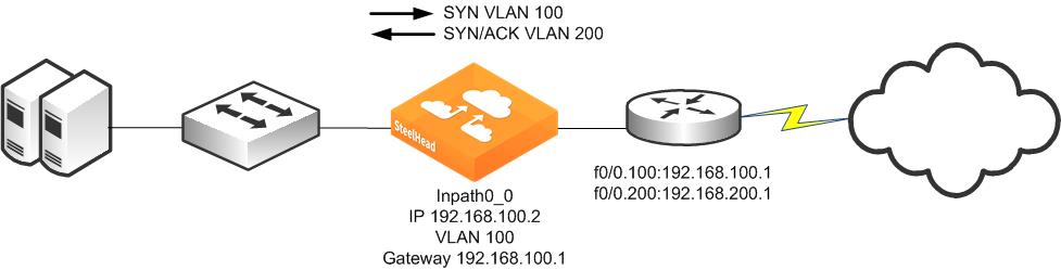
Maintaining the VLAN IDs in this manner requires using the vlan-conn-based and mac-match-vlan commands, which are enabled by default in RiOS 6.0 or later, and the other commands listed in the following configuration example.
In-path rules can use VLAN tags as matching parameters, which allows you to control optimization based on VLAN tags, along with other information such as IP addresses, subnets, or TCP ports.
Configuring a SteelHead on an 802.1Q Trunk Link
Figure: SteelHead Deployed Physically In-Path on an 802.1Q Trunk Link shows a SteelHead deployed physically in-path on an 802.1Q trunk link. Two VLANS are present on the in-path link: VLAN 10, which contains subnet 192.168.10.0/24, and VLAN 20, which contains subnet 192.168.20.0/24. The SteelHead is given an in-path IP address in the 192.168.10.0/24 subnet. The SteelHead is configured to use VLAN 10 for its in-path interface and to use the routers subinterface IP address as its default gateway. Even though the SteelHead has an in-path IP address in subnet 192.168.10.0/24 and VLAN 10, it can optimize traffic in VLAN 20.
Figure: SteelHead Deployed Physically In-Path on an 802.1Q Trunk Link
To deploy a SteelHead physically in-path on an 802.1Q trunk link
1. On the SteelHead, connect to the CLI and enter the following commands:
in-path enable
interface inpath0_0 ip address 192.168.10.2 /24
ip in-path-gateway inpath0_0 192.168.10.1
in-path interface inpath0_0 vlan 10
in-path simplified routing all
in-path peering auto
in-path probe-ftp-data
in-path probe-mapi-data
in-path simplified mac-def-gw-only
in-path mac-match-vlan
in-path vlan-conn-based
no in-path peer-probe-cach
no in-path probe-caching enable
in-path mac-except-locl
Capturing Network Traces Using tcpdump
Use caution when using network traces on trunk links. If you configure a TCP dump filter that restricts the captured packets to a specified set (for example, based on IP addresses or ports), by default tcpdump does not capture packets with an 802.1Q tag.
To capture packets with an 802.1Q tag, you must prefix the filter string with the keyword vlan. Enter the tcpdump -i wanX_Y vlan and host command.
For details, see the Riverbed Command-Line Interface Reference Manual.
Layer-2 WAN Deployments
The types of Layer-2 WANs as follows:
Layer-2 WANs
On a Layer-2 WAN, Riverbed recommends setting the LAN router closest to the SteelHead as its in-path default gateway. For example, in
Figure: SteelHeads Deployed in a Layer-2 WAN, SteelHeadA must use 192.168.255.1 as its in-path default gateway and SteelHeadB must use 192.168.255.2 as its in-path default gateway.
Figure: SteelHeads Deployed in a Layer-2 WAN
If the links to the WAN carry 802.1Q tagged packets, and if the WAN service provider routes packets based on 802.1Q tags, it is necessary to configure the SteelHeads for 802.1Q deployment and to use the full address transparency mode.
For information about full address transparency mode, see
Full Address Transparency.
Broadcast Layer-2 WANs
A Layer-2 broadcast network over the WAN is very similar to a Layer-2 WAN. However, a Layer-2 broadcast WAN behaves like a hub, whereby packets from each site are replicated over the WAN to all the other sites. For example, in
Figure: A Layer-2 Broadcast WAN Deployment, Router 2 can detect traffic between 172.30.2.1 and 10.10.2.1.
Figure: A Layer-2 Broadcast WAN Deployment
When deploying SteelHeads in a Layer-2 broadcast WAN, you must ensure that the correct SteelHead is handling the traffic. Furthermore, a Layer-2 broadcast WAN is not compatible with simplified routing; therefore, you must use static routes to avoid packet ricochet.
In
Figure: A Layer-2 Broadcast WAN Deployment, when 172.30.2.1 sends a SYN packet toward 10.10.2.1, SteelHeadA adds its probe option to the SYN packet (SYN+). The correct SteelHead that responds to this packet is SteelHeadB, because it is closest to the 10.10.2.1 server. However, because of the Layer-2 broadcast WAN, SteelHeadC would also detect the SYN+ packet and respond to SteelHeadA. This behavior creates two probe responses (SYN/ACK+) from two separate SteelHeads.
If the latency between SteelHeadA and SteelHeadC is lower than that of SteelHeadA and SteelHeadB, then SteelHeadA receives the probe response from SteelHeadC first. When the probe response SteelHead B arrives at SteelHeadA, SteelHeadA ignores the probe response, because it has already received a probe response from SteelHeadC.
This situation is undesirable, because SteelHeadA must be peering with SteelHeadB and not SteelHeadC when trying to reach the 10.10.2.1 server. To avoid this situation, enter the in-path broadcast support enable command.
When broadcast support is enabled, the SteelHead checks its routing table to see whether it uses its LAN or WAN interface to reach the destination IP. If the destination IP is reachable through the LAN, the appliance sends a probe response to the sender. Otherwise, it simply ignores the probe request.
Alternatively, you can use a fixed-target rule to define the SteelHead peers. However, fixed-target rules might not be scalable for larger deployments.
VLAN Bridging Deployments
This section describes the use of virtual LAN (VLAN) bridging. This section includes the following topics:
Overview of VLAN Bridging Deployment
The term VLAN bridging refers to a network design in which both the LAN and WAN ports of a SteelHead's in-path interface are connected to a single switch or router. The switch or router is then configured so that traffic to be optimized must pass through the SteelHead—by forcing the traffic's Layer-2 path to or from the WAN to pass through the in-path interface.
VLAN bridging is useful in network environments in which it is difficult to install a SteelHead physically in-path. For example, if fiber interfaces are needed for a physical in-path installation, but only copper interfaces are available on the SteelHead, you can use VLAN bridging as a simpler alternative to WCCP or PBR.
Figure: VLAN Bridging Principles shows the principles of VLAN bridging. An existing switch or router is divided into two separate VLANs, and the SteelHead's LAN and WAN interfaces are used as the Layer-2 bridge that connects the VLANs.
Figure: VLAN Bridging Principles
VLAN Bridging Considerations
A VLAN bridging deployment has the same features and functionality as a physically in-path SteelHead, with the exception of 802.1Q VLAN trunking.
Consider the following guidelines when you use a VLAN bridging deployment:
• You can use an 802.1Q trunk with VLAN bridging between multiple VLANs on the same in-path interface, but doing this requires switch-specific features.
• Use the same cables for the WAN and LAN interfaces—the same as you use for physical in-path deployments.
• The switch detects the same MAC addresses in two different VLANs. Because most switches have separate MAC address tables per VLAN (independent VLAN learning, or IVL), some older switches can have only one MAC table for all VLANs (shared VLAN learning). Use only switches that have IVL with VLAN bridging.
• Verify that the switch allows access to its management IP address from multiple VLANs. Avoid using a switch whose management IP is only reachable from the default VLAN, because doing this prevents managing the switch. Some switches assign their management IP address to the default VLAN and cannot be altered—for example, the Cisco 2950 switch.
VLAN Bridging Variations
The variations of VLAN bridging are as follows:
Layer-2 VLAN Bridging
In a Layer-2 VLAN bridging deployment, the SteelHead is connected by VLANs on the Layer-2 switch. All traffic is bridged through the SteelHeads as it passes to and from the WAN routers.
Figure: Layer-2 VLAN Bridging shows a Layer-2 VLAN bridging deployment.
Figure: Layer-2 VLAN Bridging
Note the following:
• VLAN 100 and VLAN 200 are Layer-2 VLANs.
• The default gateway of the hosts on the LAN must point to the router interface IP address.
• VLAN 100 contains the switch ports of the hosts and the switch port connected to the lan0_0 interface of the SteelHead.
• VLAN 200 contains the switch ports, the router, and the wan0_0 interface of the SteelHead.
• The default gateway of the SteelHead is the IP address of the WAN router.
Layer-3 VLAN Bridging
In a Layer-3 VLAN bridging deployment, the SteelHead is connected across Layer-3 and Layer-2 VLANs on a Layer-2/Layer-3 switch. All traffic is switched through the SteelHead as it passes to and from the WAN router.
Figure: Layer-3 VLAN Bridging shows a Layer-3 VLAN bridging deployment.
Figure: Layer-3 VLAN Bridging
Note the following:
• Hosts on the VLAN 100 must point to VLAN 100 IP address as the default gateway.
• VLAN 100 contains the switch ports of the hosts, and the switch port connected to the lan0_0 interface of the SteelHead.
• VLAN 200 contains the switch ports, the router, and the wan0_0 interface that the SteelHead is connected to.
• The default gateway of the SteelHead is the IP address of the WAN router.
Multiple VLAN Bridging with VLAN Mapping
A limitation in Layer-2 VLAN bridging and Layer-3 VLAN bridging is that a single in-path interface can only bridge two different VLANs. If the SteelHead-connected switch ports are configured to be 802.1Q trunks (so that many VLANs can be sent or received), the switch does not bridge traffic for the VLANs across the ports.
To connect to multiple VLANs, you need a switch that supports
VLAN mapping (also referred to as
VLAN translation or
VLAN normalization, depending on the switch vendor). VLAN mapping allows a trunk interface to change the 802.1Q tag. You must configure the switch with the mapping of one VLAN tag (used on the LAN side of the SteelHead) to another VLAN tag (used on the WAN side of the SteelHead) for packets to be sent or received.
Figure: Multiple VLAN Bridging with VLAN Mapping shows multiple VLAN bridging with VLAN mapping deployment.
Figure: Multiple VLAN Bridging with VLAN Mapping
The following functionality makes it possible to optimize multiple VLANs with VLAN bridging:
• The VLAN mapping function on a switch changes the VLAN tags.
• VLAN mapping takes 802.1Q tagged traffic from an incoming trunk switch-port and maps it to a different local VLAN.
For information about configuring your specific hardware, refer to the documentation provided with your switch.