WAN Visibility Modes
This chapter describes SteelHead WAN visibility modes and how to configure them. This chapter includes the following sections:
For information about the factors you must consider before you design and deploy the SteelHead in a network environment, see
Choosing the Right SteelHead Model.
Overview of WAN Visibility
Each LAN-side TCP connection that is optimized by a SteelHead is carried on a unique WAN-side connection. By configuring a WAN visibility mode for some or all optimized connections, you can control which IP addresses and TCP ports are used on these WAN-side TCP connections.
RiOS 6.0 or later offers the following options for configuring WAN visibility modes:
• Correct addressing - WAN-side connections use SteelHead IP addresses and SteelHead server ports.
• Transparent addressing - The following are transparent addressing options:
– Port transparency - WAN-side connections use SteelHead IP addresses but use TCP server ports that mirror the LAN-side connection.
– Full transparency - WAN-side connections mirror all IP addresses and TCP ports used on the LAN-side connection.
– Full transparency with forward reset - The same as full transparency, with an additional packet during autodiscovery to aid with integration of stateful network devices on the WAN.
The most suitable WAN visibility mode depends primarily on your existing network configuration. For example, if you manage IP address-based or TCP port-based QoS policies for optimized traffic on your WAN or WAN routers, you might use full address transparency or port transparency. However, if you need your optimized traffic to pass through a content-scanning firewall that creates alarms when application ports are used on optimized traffic payload, you might use correct addressing instead. You can configure WAN visibility modes on the client-side SteelHead (where the connection is initiated).
There can be different types of addressing modes on the same SteelHead. Choose the most appropriate addressing mode for your configuration, based on IP addresses, subnets, TCP ports, and VLAN.
Correct Addressing
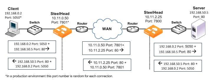
Correct addressing uses SteelHead IP addresses and port numbers in the TCP/IP packet header fields for optimized traffic in both directions across the WAN. By default, SteelHeads use correct addressing.
Figure: Correct Addressing shows TCP/IP packet headers when correct addressing is used. The IP addresses and port numbers of your SteelHeads are visible across your WAN. Refer to
Figure: Correct Addressing to compare it to port transparency (
Figure: Port Transparency) and full address transparency (
Figure: Full Address Transparency) packet headers.
Figure: Correct Addressing
Correct addressing uses the following values in your TCP/IP packet headers in both directions:
• Client to client-side SteelHead - Client IP address and port + server IP address and port.
• Client-side SteelHead to server-side SteelHead - Client-side SteelHead IP address and port + server-side SteelHead IP address and port.
• Server-side SteelHead to server - Client IP address and port + server IP address and port.
Correct addressing avoids networking risks that are inherent to enabling transparent addressing.
For information about configuring correct addressing, see
Configuring WAN Visibility Modes. For information about avoiding network risks, see
Implications of Transparent Addressing.
Correct addressing enables you to use the connection pooling optimization feature. Connection pooling works only for connections optimized using correct addressing. Connection pooling enables SteelHeads to create several TCP connections between each other before they are needed. When transparent addressing is enabled, SteelHeads cannot create the TCP connections in advance because they cannot detect what types of client and server IP addresses and ports are needed.
For information about connection pooling, see
Connection Pooling.
Transparent Addressing
This section describes port transparency and full address transparency. This section includes the following topics:
Transparent addressing reuses client and server addressing for optimized traffic across the WAN. Traffic is optimized, although addressing appears to be unchanged. Both optimized and pass-through traffic present identical addressing information to the router and network monitoring devices.
In RiOS 5.0.x or later, transparent addressing can be used in conjunction with many deployment configurations and features, including, but not limited to:
• physical in-path deployments (serial clusters, primary/backup, and deployments using connection forwarding).
• virtual in-path deployments (WCCP, PBR, Layer-4 switching, and SteelHead Interceptor deployments).
• autodiscovery, including enhanced autodiscovery.
• asymmetric route detection.
• QoS marking and classification.
• flow data export.
Transparent addressing does not support the following deployment configurations:
• Server-side out-of-path SteelHead configurations
• Fixed-target rules
• Connection pooling
You configure transparent addressing on the client-side SteelHead (where the connection is initiated). Both the server-side and the client-side SteelHeads must support transparent addressing (RiOS 5.0.x or later) for transparent addressing to work. You can configure a SteelHead for transparent addressing even if its peer does not support it. The connection is optimized, but it is not transparent.
When you use full or port transparency, SteelHeads add a TCP option field to the packet headers of optimized traffic. This TCP option field is sent between the SteelHeads. For transparency to work, this option must not be stripped off by intermediate network devices.
A given pair of SteelHeads can also have multiple types of transparent addressing enabled for different connections. For example, a pair of SteelHeads can use correct addressing for connections to a destination subnet and use full address transparency or port transparency for connections to another destination subnet. A pair of SteelHeads can also use correct addressing for connections to a destination port and use full address transparency or port transparency for connections to another destination subnet.
If both port transparency and full address transparency are acceptable solutions, port transparency is preferable. Port transparency avoids potential networking risks that are inherent in enabling full address transparency.
Port Transparency
Port transparency preserves your server port numbers in the TCP/IP header fields for optimized traffic in both directions across the WAN. Traffic is optimized even though the server port number in the TCP/IP header field appears to be unchanged. Routers and network monitoring devices deployed in the WAN segment between the communicating SteelHeads can view these preserved fields.
Port transparency does not require dedicated port configurations on your SteelHeads.
Port transparency provides server only port visibility. Port transparency does not provide client and server IP address visibility, nor does it provide client port visibility.
Figure: Port Transparency shows TCP/IP packet headers when port transparency is enabled. Server port numbers are visible across your WAN.
To compare port transparency packet headers to correct addressing packet headers, see
Figure: Correct Addressing.
Figure: Port Transparency
Port transparency uses the following values in your TCP/IP packet headers in both directions:
• Client to client-side SteelHead - Client IP address and port + server IP address and port.
• Client-side SteelHead to server-side SteelHead - Client-side SteelHead IP address and port + server-side SteelHead IP address with server port.
• Server-side SteelHead to server - Client IP address and port + server IP address and port.
Use port transparency if you want to manage and enforce QoS policies that are based on destination ports. If your WAN router is following traffic classification rules that are written in terms of TCP destination port numbers, port transparency enables your routers to use existing rules to classify the traffic without any changes.
Port transparency enables network analyzers deployed within the WAN (between the SteelHeads) to monitor network activity, and to capture statistics for reporting, by inspecting traffic according to its original TCP destination port number.
For information about configuring port transparency, see
Configuring WAN Visibility Modes.
Full Address Transparency
This section describes full address transparency. This section includes the following topics:
Overview of Full Address Transparency
Full address transparency preserves your client and server IP addresses and port numbers in the TCP/IP header fields for optimized traffic in both directions across the WAN. VLAN tags can also be preserved. Traffic is optimized even though these TCP/IP header fields appear to be unchanged. Routers and network monitoring devices deployed in the WAN segment between the communicating SteelHeads can view these preserved fields.
Figure: Full Address Transparency shows how TCP/IP packet headers might be addressed when full address transparency is enabled. In this example, SteelHead IP addresses and port numbers are no longer visible on the optimized connections. Client and server IP addresses and port numbers are now visible in both directions across the WAN.
When you enable full address transparency, you have several addressing options for the out-of-band (OOB) connection. The type of addressing you configure for your OOB connection ultimately determines whether the SteelHead in-path IP addresses are used in the TCP/IP packet headers.
For information about OOB, see
Out-of-Band Connection.
To compare full address transparency packet headers with correct addressing packet headers, see
Figure: Correct Addressing.
Figure: Full Address Transparency
In this example, full address transparency uses the following values in the TCP/IP packet headers in both directions:
• Client to client-side SteelHead - Client IP address and port + server IP address and port.
• Client-side SteelHead to server-side SteelHead - Client IP address and port + server IP address and port.
• Server-side SteelHead to server - Client IP address and port + server IP address and port.
For information about configuring full address transparency, see
Configuring WAN Visibility Modes.
If both port transparency and full address transparency are acceptable solutions, port transparency is preferable. Port transparency mitigates potential networking risks that are inherent in enabling full address transparency.
However, if you must use your client or server IP addresses across your WAN, full address transparency is your only configuration option. Full address transparency enables network monitoring applications deployed within the WAN (between the SteelHeads) to measure traffic sent to the WAN by the end-host. Network routers can also perform load balancing and policy-based routing. Full address transparency also enables you to manage and enforce QoS policies based on port numbers or IP addresses.
Important: When full address transparency is enabled, router QoS policies cannot distinguish between optimized and unoptimized traffic, even though an optimized packet might represent much more data.
Full address transparency also enables the use of Network Address Translation (NAT). With correct addressing, SteelHeads use their own IP addresses in the packet header, which NAT does not recognize. When full address transparency is enabled, the original client and server IP addresses are used, and the connections are recognizable to NAT. However, the type of addressing you configure for your out-of-band (OOB) connection ultimately determines whether the SteelHead in-path IP addresses are used in the TCP/IP packet headers.
Full address transparency also supports several transparency options for the OOB connection.
For information about OOB, see
Out-of-Band Connection.
Important: Some firewalls, QoS devices, and other stateful devices might require additional configuration to successfully allow full transparency connections to optimize. Search the Riverbed Knowledge Base for information about any particular device.
Configuring VLANs and Full Address Transparency
Full address transparency supports transparent VLANs. You can configure full address transparency so that optimized traffic remains on the original VLANs. Because you can keep traffic on the original VLANs, full address transparency enables you to perform VLAN-based QoS on the WAN side of the SteelHead.
Note: You must first configure WAN visibility full address transparency for VLAN transparency to function correctly.
To configure full address transparency for a VLAN
• On the SteelHead, connect to the CLI and enter the following commands:
enable
configure terminal
in-path peering auto
in-path simplified routing all
in-path vlan-conn-based
in-path mac-match-vlan
no in-path probe-caching enable
in-path probe-ftp-data
in-path probe-mapi-data
write memory
restart
Note: You must save your changes or they are lost upon reboot. Restart the optimization service for the changes to take effect.
If packets on your network use two different VLANs in the forward and reverse directions, see the Riverbed Knowledge Base article,
Understanding VLANs and Transparency, located at
https://supportkb.riverbed.com/support/index?page=content&id=S15176.Full Address Transparency with Forward Reset
The Full Address Transparency with Forward Reset mode is similar to the Full Address Transparency WAN visibility mode. Like Full Address Transparency, use this mode to preserve the client and server IP addresses and TCP ports used for the WAN-side TCP connections between SteelHeads. The difference between the two modes happens during the autodiscovery phase, during which TCP reset packets are transmitted on the WAN. These packets help network devices like stateful firewalls separate TCP state between the SteelHeads discovery phase and the data transmission phase.
Except for the TCP reset packets during the discovery phase, there are no other differences between Full Address Transparency and Full Address Transparency with Forward Reset, including the addressing of the WAN-side TCP connection, considerations for 802.1Q VLAN tracking, and OOB transparency.
Figure: Full Transparency with Forward Reset shows the autodiscovery packet flow when using the Full Transparency with Forward Reset mode and enhanced autodiscovery. The packet marked
Forward Reset is the only difference between this mode and the Full Transparency mode.
Figure: Full Transparency with Forward Reset
In Full Address Transparency with Forward Reset mode, TCP reset packets are transmitted by the initiating SteelHead immediately after the remote SteelHead is discovered. The reset packets traverse the WAN and are absorbed by the remote SteelHead. The packets aid any TCP-aware device on the WAN to understand that the sequence numbers used during the autodiscovery phase is different from the sequence numbers used during the data transmission phase. Example devices include:
• firewalls or other network security devices on the WAN that statefully track TCP sessions, and devices that might block WAN-side SteelHead connections from being created due to seeing different sequence numbers in use.
• QoS devices that alter TCP headers to affect congestion. Examples include Blue Coat Packetshaper appliances using rate policies, and the Allot Netenforcer.
Important: Some firewalls, QoS devices, and other stateful devices might require additional configuration to successfully optimize connections using the full transparency with forward reset connections to operate. Search the Riverbed Knowledge Base for information about any particular device.
Implications of Transparent Addressing
This section describes some of the common problems that are inherent to transparent addressing:
The problems described in this section occur with all proxy-based solutions.
Stateful Systems
Transparent addressing can have an impact on systems that monitor or alter the state of TCP connections on the WAN for reporting, security, or congestion control. For example, some stateful firewalls might detect the difference in sequence numbers between the autodiscovery phase and the data transmission phase of fully transparent connections, and then react by raising alarms or disallowing connections between the SteelHeads. Using the Full Transparency with Forward Reset mode might alleviate this issue, but might also cause monitoring systems to record more TCP connection activity across the WAN than is actually present.
Transparent addressing also does not work with intrusion detection and prevention systems that perform stateful packet inspection. SteelHeads use a proprietary Riverbed application protocol to communicate. When intrusion detection and prevention systems perform stateful packet inspections, they expect an application protocol based on the port numbers of the original client and server connection. When these systems discover the Riverbed proprietary application protocol, they perceive this as a mismatch and either log the packet, drop it, trigger an alarm, or perform all these actions.
You can avoid these problems with stateful systems, which are inherent to transparent addressing, by using correct addressing.
Network Design Issues
This section describes some of the common networking problems that are inherent to transparent addressing. This section includes the following topics:
Network Asymmetry
Enabling full address transparency increases the likelihood of problems inherent to asymmetric routing.
For a connection to be optimized, its packets to and from its LAN hosts must pass through either:
• one or more in-path interfaces on the same SteelHead, or
• one or more in-path interfaces on SteelHeads that are configured as connection-forwarding neighbors.
When full address transparency is used, WAN-side routers detect the client or server addresses in the optimized connections packets and use those addresses to make routing decisions. If the router has a route to the client or server that does not pass through a SteelHead, and it transmits the optimized packets on that route, the optimized and LAN-side connections might fail.
Figure: Server-Side Asymmetric Network shows a network in which a link to the server location does not have a SteelHead installed. Depending on the exact routing configuration in the
Figure: Server-Side Asymmetric Network, it is possible that correct addressing can work, but full transparency does not, because the optimized traffic from the client side might be sent through the link that does not have the SteelHead.
Figure: Server-Side Asymmetric Network
To ensure that all required traffic is optimized and accelerated, you must install a SteelHead on every possible path that a packet traverses. Connection forwarding must also be configured and enabled for each SteelHead.
If there is a path that does not have a SteelHead, it is possible that some traffic will not be optimized.
You can avoid this type of asymmetric routing problem, which is inherent to transparent addressing, by using correct addressing.
For information about connection forwarding, see
Connection Forwarding. For information about how to eliminate asymmetric routing problems, see
Troubleshooting SteelHead Deployment Problems.
Note: With RiOS 3.0.x or later, you can configure your SteelHeads to automatically detect and report asymmetric routes within your network. For details, see the SteelHead Management Console User’s Guide.
Misrouting Optimized Traffic
Enabling transparent addressing introduces the likelihood of misrouting optimized traffic in the event of a SteelHead failure.
SteelHeads use a proprietary Riverbed protocol to communicate. Normally, a functioning server-side SteelHead receives a packet from the WAN and converts the packet to its native format before forwarding it to the server.
In an environment in which transparent addressing is used, if the server-side SteelHead is not functioning, or if a packet is routed along an alternative network path, the packet might go from the client-side SteelHead directly to the server. Because the server-side SteelHead does not have an opportunity to convert the packet to its native format, the server cannot recognize it, and the connection fails.
In most cases, the server is able to detect whether a packet contains invalid payload information or, in this case, has an unrecognizable format, and rejects the packet. Assuming that the server does detect that the format is unrecognizable, the server rejects the packet and resets the TCP connection. If the client TCP connection is reset, the client can reconnect to the server without any SteelHead involvement.
This type of traffic misrouting can occur in both directions across the WAN. If the client-side SteelHead experiences a failure, or if an alternate network path exists from the server to the client, traffic might go from the server-side SteelHead directly to the client.
Important: Before enabling and using full address transparency, carefully consider the risks and exposures in the event that a server accepts and routes a packet that has an unrecognizable format.
Figure: Transparent Addressing and Misrouting Optimized Traffic shows traffic being misrouted when the server-side SteelHead fails on a network using transparent addressing.
Figure: Transparent Addressing and Misrouting Optimized Traffic
The failure scenario follows this process:
1. Client A sends HTTP data to the server.
2. SteelHead B receives the HTTP data optimizes it. SteelHead B eventually transmits packets carrying the optimized data toward SteelHead C, but due to the transparent addressing mode, the packets are addressed to Server D.
3. SteelHead C suffers a failure and is in fail-to-wire mode, so all packets are traversing it, including the packets from SteelHead B.
4. Server D receives the packets from SteelHead B, but does not recognize the packet format, so the connection fails or suffers an application-dependent error.
You can avoid this type of misrouting problem, which is inherent to transparent addressing, by using correct addressing.
If correct addressing is configured for this scenario, the client-side SteelHead detects that the server-side SteelHead has failed. The client-side SteelHead automatically resets the client connection, allowing the client to connect directly to the server without SteelHead involvement.
Firewalls Located Between SteelHeads
There are addressing issues that you must be aware of if your firewall inspects traffic between two SteelHeads (
Figure: Firewalls and Transparent Addressing).
Figure: Firewalls and Transparent Addressing
The following table summarizes deployment configurations that might affect addressing when a firewall inspects traffic between two SteelHeads. Firewall behavior differs, depending on the type of addressing being used. A Yes value indicates that your firewall will perform as expected.
Firewall Configuration | Full Address Transparency | Port Transparency | Correct Addressing |
Firewall rules based on a server port | Yes | Yes Note: This configuration does not support active FTP. | Yes, if the following conditions are true: • The firewall checks on the session establishment. • The firewall is enabled. • The firewall allows port 7800 traffic. |
Firewall rules based on IP addresses | Yes | Yes, if the following conditions are true: • IP-based rules are based only on server addresses. • Probe caching is disabled. | Yes, if the following conditions are true: • The firewall checks on the session establishment. • The firewall is enabled. • Probe caching is disabled. For information about disabling probe caching, see the Riverbed Command-Line Interface Reference Manual. |
For information about stateful firewalls and intrusion detection and prevention systems, see
Stateful Systems.
Integration into Networks Using NAT
Network address translation (NAT) affects the addresses the SteelHead uses in different ways, depending on which addressing mode is in use. This section provides several NAT deployment scenarios using various addressing modes:
NAT Deployment Using Enhanced Autodiscovery and Full Transparency
Figure: Enhanced Autodiscovery and Full Transparency Mode shows full transparency addressing mode. The client and server IP addresses are preserved, and the presence of the full transparency TCP is a signal to the server-side SteelHead that it can use the addresses arriving from the WAN. This behavior ensures that any translation is preserved for optimized traffic.
Figure: Enhanced Autodiscovery and Full Transparency Mode
NAT Deployment Using Fixed-Target Rules
When you use a fixed-target rule to the primary IP address of a remote SteelHead, the remote SteelHead makes a connection to the destination IP address detected on the initiating SteelHead.
Figure: Fixed-Target Rule to Primary IP Address shows that the source address is the primary IP address of the remote SteelHead.
When you use a fixed-target rule to the in-path IP address of a remote SteelHead, the remote SteelHead makes a connection to the destination IP address detected on the initiating SteelHead. The remote SteelHead also uses the same source address detected on the initiating SteelHead.
Figure: Fixed-Target Rule to Primary IP Address
In
Figure: Fixed-Target Rule to Primary IP Address, the out-of-path packet flow on incoming connection requests is very similar to an established in-path partnership. However, there is an important distinction in that the IP address of the server-side SteelHead replaces the IP address of the client in communication between the server-side SteelHead and the destination server. The traffic travels the following route:
1. The packet is created coming from the initiator client (C) IP address to the destination server (S) IP address.
2. The client-side SteelHead sends a packet to port 7810 on the server-side SteelHead, requesting to open a session.
3. The server-side SteelHead acknowledges the connection request.
4. The client-side SteelHead acknowledges the connection.
5. The client-side SteelHead sends session setup information to the server-side SteelHead.
6. The server-side SteelHead forwards the original connection request to the destination server, replacing the client IP address with the server-side SteelHead IP address.
7. The destination server acknowledges the connection request.
8. The server-side SteelHead sends a packet acknowledgment to the destination server.
9. The server-side SteelHead sends the connection acknowledgment to the client-side SteelHead.
10. The client-side SteelHead sends the acknowledgment packet to the requesting client.
11. The client sends an acknowledgment to the destination server.
12. The client-side SteelHead discards the client acknowledgment.
Some applications and protocols require that the server initiate a new session or that they see the IP address of the requesting client. These applications and protocols do not function in this configuration. Consider using an in-path deployment, a WCCP deployment, or use rules on the SteelHead to pass through this traffic.
NAT Deployment Using Correct and Port Transparency Addressing Modes
In both correct and port transparency addressing modes, whatever IP addresses are detected on the initiating SteelHead (typically, the client-side SteelHead) are used by the corresponding SteelHead on the remote side as
Figure: Enhanced Autodiscovery in Correct and Port Transparency Modes shows. This deployment can bypass any NAT that occurs in the WAN between the SteelHeads. To ensure that NAT is still used for the optimized traffic, you must configure the full transparency addressing mode for this traffic.
Figure: Enhanced Autodiscovery in Correct and Port Transparency Modes
In this example, the TCP connection request travels the following route:
1. The packet is created coming from the initiator client (C) IP address to the destination server (S) IP address.
2. The client-side SteelHead adds a probe to the TCP connection request.
3. The server-side SteelHead sends not last notify immediately after receiving the probe.
4. The server-side SteelHead forwards the original connection request to the destination server using client IP:port as source address, with a sequence number 2.
5. The destination server acknowledges the client connection request.
6. The server-side SteelHead intercepts the return packet.
7. The server-side SteelHead sends a packet acknowledgment to the destination server on behalf of the client.
8. The server-side SteelHead acknowledges the client-side SteelHead, and it sends a notification with a probe response indicating that it is the last SteelHead before the server.
9. The client-side SteelHead sends a request to open port 7800 on the server-side SteelHead.
10. The server-side SteelHead acknowledges the connection request.
11. The client-side SteelHead acknowledges the connection.
12. The client-side SteelHead sends session setup information to the server-side SteelHead.
13. The server-side SteelHead connection sends an acknowledgment to the client-side SteelHead.
14. The client-side SteelHead sends the connection acknowledgment to the requesting client.
15. The client sends an acknowledgment to the destination server.
16. The client-side SteelHead discards the client acknowledgment.
Client-Side Source NAT Using Enhanced Autodiscovery and Full Transparency
Figure: Full Transparency, Enhanced Autodiscovery, and Client-Side Source NAT shows a client-side source NAT deployment using enhanced autodiscovery and full address transparency. In this configuration, the presence of the full transparency TCP option with autodiscovery probe is a signal to the server-side SteelHead that it can use the addresses arriving from the WAN. Because the server-side addresses are reachable from the client side, when the client-side SteelHead makes its out-of-band connection to the server-side SteelHead, the address it uses is valid and is properly translated across the WAN.
Figure: Full Transparency, Enhanced Autodiscovery, and Client-Side Source NAT
Failed Client-Side Source NAT Deployment Using Enhanced Autodiscovery and Correct Addressing
Figure: Enhanced Autodiscovery, Correct Addressing, and Client-Side Source NAT shows a deployment in which NAT is occurring at the client location. In this example, enhanced autodiscovery with correct addressing does not work because the server-side SteelHead cannot match the client connection that it originally sees in the SYN+ with the pre-NAT (original) client IP address that is sent as part of the setup information.
Figure: Enhanced Autodiscovery, Correct Addressing, and Client-Side Source NAT
Dual NAT Deployment Using Enhanced Autodiscovery and Full Transparency
Figure: Enhanced Autodiscovery, Full Transparency, OOB Transparency, and Dual NAT shows NAT used at the client and the server. In this network, full transparency and some form of OOB transparency is required for successful connection establishment and optimization.
Figure: Enhanced Autodiscovery, Full Transparency, OOB Transparency, and Dual NAT
Failed Dual NAT Deployment Using Enhanced Autodiscovery and Correct Addressing
Figure: Enhanced Autodiscovery, Correct Addressing, Dual NAT, Resulting in Half-Opened Connection shows a deployment in which NAT is occurring at both the client and server locations. In this example, enhanced autodiscovery with correct addressing is unlikely to work, because the probe response from the server-side SteelHead included the WA2a internal IP address for the server-side SteelHead.
Figure: Enhanced Autodiscovery, Correct Addressing, Dual NAT, Resulting in Half-Opened Connection
Out-of-Band Connection
This section describes transparency options for the out-of-band (OOB) connection. This section includes the following topics:
Overview of OOB Connections and Addressing Modes
A SteelHead OOB connection is a TCP connection that SteelHeads establish with each other when they begin optimizing traffic to exchange capabilities and feature information and to detect failures. A SteelHead creates an OOB connection for each pair of local and remote in-path interfaces that are used when optimizing connections. OOB connections are created by the SteelHead closest to the initiating side of the optimized connection.
The addresses and ports used by OOB connections depend on the addressing mode used for the first optimized connection between SteelHeads. If the addressing mode for the first connection is correct addressing or port transparency, the OOB connection uses correct addressing. If the first connection is full transparency, the default behavior is to make the OOB connection use correct addressing, but you can alter this behavior such that the connection uses a form of network transparency.
In some environments, it might be necessary to make OOB connections use some form of network transparency: for example, the network is unable to route between the in-path IP addresses or VLANs of SteelHeads that are optimizing traffic. Two options for OOB transparency exist:
• Destination transparency
• Full transparency
The two options differ in which source IP address and TCP port are used. For details see
Configuring OOB Connection Destination Transparency and
Configuring OOB Connection Full Transparency.
Configuring OOB Connection Destination Transparency
Figure: OOB Connection Destination Transparency shows TCP/IP packet headers when OOB connection destination transparency is enabled.
Figure: OOB Connection Destination Transparency
OOB connection destination transparency uses the following values in the TCP/IP packet headers in both directions across the WAN:
• Client-side SteelHead IP address and an ephemeral port number chosen by the client-side SteelHead + server IP address and port number.
• SteelHeads use the server IP address and port number from the first optimized connection.
Use OOB connection destination transparency if the client-side SteelHead cannot establish the OOB connection to the server-side SteelHead.
Note: You must first configure WAN visibility full address transparency for OOB connection destination transparency to function correctly.
To enable OOB connection destination transparency
• Connect to the CLI on the client-side SteelHead and enter the following commands:
enable
configure terminal
in-path peering oobtransparency mode destination
write memory
Note: The changes take effect immediately. You must save your changes or they are lost upon reboot.
To disable OOB connection destination transparency
• Connect to the Riverbed CLI on the client-side SteelHead and enter the following commands:
enable
configure terminal
in-path peering oobtransparency mode none
write memory
Note: The changes take effect immediately. You must save your changes or they are lost upon reboot.
Configuring OOB Connection Full Transparency
Figure: OOB Connection Full Transparency shows TCP/IP packet headers when OOB connection full transparency is enabled.
Figure: OOB Connection Full Transparency
OOB connection full transparency uses the following values in the TCP/IP packet headers in both directions across the WAN:
• Client IP address and client-side SteelHead predetermined port number 708 + server IP address and port number.
SteelHeads use the client IP address and the server IP address and port number from the first optimized connection.
If the client is already using port 708 to connect to the destination server, enter the in-path peering oobtransparency port <port-number> command to change the client-side SteelHead predetermined port number.
OOB connection full transparency supports SteelHeads deployed on trunks. Because you can configure full address transparency so that optimized traffic remains on the original VLAN, you no longer need for a SteelHead VLAN.
Use OOB connection full transparency if your network is unable to route between SteelHead in-path IP addresses or in-path VLANs or you do not want to see SteelHead IP addresses used for the OOB connection.
You must first configure WAN visibility full address transparency for OOB connection full transparency to function correctly. For details, see
Full Address Transparency.
To enable OOB connection full transparency
• Connect to the CLI on the client-side SteelHead and enter the following commands:
enable
configure terminal
in-path peering oobtransparency mode full
write memory
The changes take effect immediately. You must save your changes or they are lost upon reboot.
To disable OOB connection full transparency
• Connect to the CLI on the client-side SteelHead and enter the following commands:
enable
configure terminal
in-path peering oobtransparency mode none
write memory
The changes take effect immediately. You must save your changes or they are lost upon reboot.
Configuring WAN Visibility Modes
This section describes how to configure WAN visibility modes using an example deployment and the RiOS CLI.
You configure WAN visibility modes by creating an in-path rule on the client-side SteelHead (where the connection is initiated). By default, the rule is placed before the default in-path rule and after the secure, interactive, and RBT-proto rules.
For transparent addressing to function correctly, both of the SteelHeads must have RiOS 5.0.x or later installed. If one SteelHead does not support transparent addressing (that is, it has RiOS 4.1 or earlier installed), the SteelHead attempting to optimize a connection in one of the transparent addressing modes automatically reverts to correct addressing mode, and optimization continues.
By default, SteelHeads use correct addressing (for all RiOS versions).
Figure: Example Deployment for Configuring WAN Visibility Modes shows the IP addresses and ports used in the example deployments.
Figure: Example Deployment for Configuring WAN Visibility Modes
The following table summarizes the port transparency commands.
Action | CLI Command |
Enable port transparency for a specific server. | in-path rule auto-discover wan-visibility port dstaddr 192.168.50.1/32 dstport 80 |
Enable full address transparency for a specific group of servers, and port transparency for servers not in the group. | in-path rule auto-discover wan-visibility full dstaddr 192.168.0.0/24 in-path rule auto-discover wan-visibility port Important: In this example, the first in-path rule must precede the second in-path rule in the rule list. To specify the placement of a rule in the list, use the rulenum keyword and value. For details, see the Riverbed Command-Line Interface Reference Manual. |
Disable port transparency. | Delete the in-path rule that enables it. For information about deleting in-path rules, see the Riverbed Command-Line Interface Reference Manual. |
The following table summarizes the full address transparency commands.
Action | CLI Command |
Enable full address transparency globally. | in-path rule auto-discover wan-visibility full |
Enable full address transparency for servers in a specific IP address range. | in-path rule auto-discover wan-visibility full dstaddr 192.168.0.0/16 |
Enable full address transparency for a specific server. | in-path rule auto-discover wan-visibility full dstaddr 192.168.50.1/32 |
Enable full address transparency for a specific group of servers, and enable port transparency for servers not in the group. | in-path rule auto-discover wan-visibility full dstaddr 192.168.0.0/24 in-path rule auto-discover wan-visibility port Important: In this example, the first in-path rule must precede the second in-path rule in the rule list. To specify the placement of a rule in the list, use the rulenum keyword and value. For details, see the Riverbed Command-Line Interface Reference Manual. |
Disable full address transparency | Delete the in-path rule that enables it. For information about deleting in-path rules, see the Riverbed Command-Line Interface Reference Manual. |