Working with Organizations
This topic describes how to define and customize organizations in SteelConnect. It includes these sections:
Organization overview
An organization is a company representing an end customer. It contains the customer details, sites, devices, zones associated with the devices, the uplinks, and so on.
You can assign administrative rights to individual administrator accounts per organization. You can also manage appliances and licensing per organization.
Defining an organization
SCM uses these terms to describe your company:
•Organization - A company representing an end customer. You can assign administrative rights to individual administrator accounts per organization. You can also manage appliances and licensing per organization.
•Site - A physical location of one or more office buildings, a hosting center, or a cloud location that make up the organization. A site houses a SteelConnect gateway and uses a permanent DNS alias. Every site requires a local network zone and at least one internet uplink. When you create a site, the zone is automatically created and an uplink is automatically created for the internet path.
•Zone - Layer 2 network segments or VLANs within sites that are VLAN-tagged traffic. A zone always has a VLAN tag assigned to it.
To create an organization
1. Choose Organization.
2. Click New.
3. Type a short and log name for the organization.
4. Type a city and street address.
5. Click the search selector and select a country.
6. Click the search selector and select a time zone.
7. Click Submit.
To edit an organization
SCM ships with a default organization. This section explains the default settings and how to create a new site within an organization.
After adding the company name, you’ll add basic information. You can always change and customize this information later.
You can change settings associated with an organization using the tabs on the Organization page.
The Organization page contains important global settings for internet breakout, NTP, numbering for VLANs, and default subnet IPs, social media integration, firmware upgrade schedules, and more.
Defining an organization
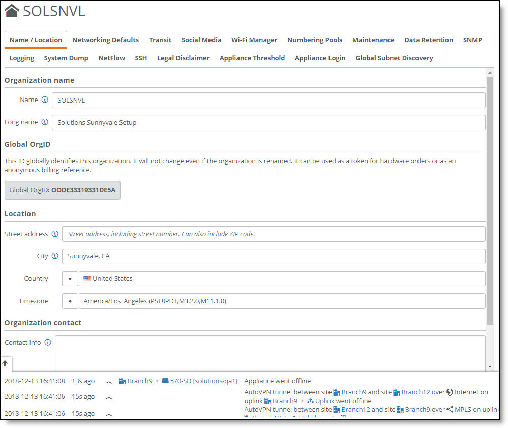
Name/Location
This tab sets the name referenced on various SCM pages and the reports. This tab also displays the global organization ID generated by SCM that uniquely identifies the organization system wide. You can also define the location and the contact information for the entire organization.
Because changing the organization name at the organization level will change the URL needed to access the organization, you can only change the organization name or long name from the Realm level.
To change the organization name or long name
1. Go to the realm level.
2. Choose Organizations.
3. Select the organization.
4. Select the Name/Location tab.
5. Change the name or long name.
6. Click Submit.
Networking Defaults
This tab sets important global preferences for an organization.
Networking defaults
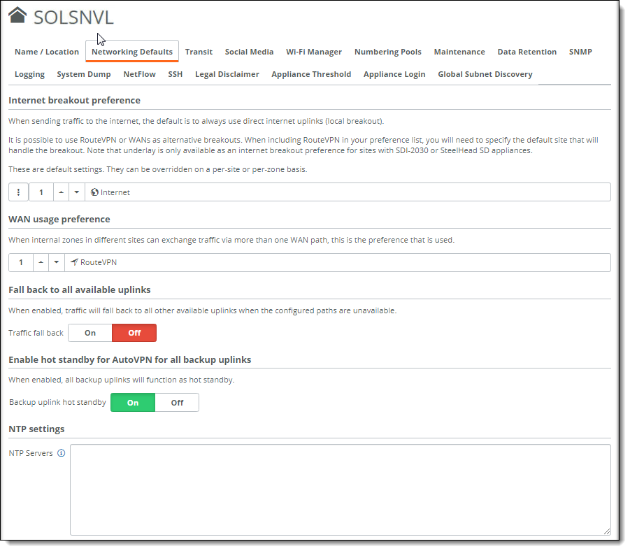
Setting the internet breakout preference
This setting determines how you want internet traffic to flow for each site that you deploy throughout the organization. When sending traffic to the internet, the default is to send internet-bound traffic directly out the local connection. You can also use RouteVPN or WANs as alternative breakouts. When including RouteVPN in your preference list, specify the default site that will handle the breakout. For details, see
Local internet breakout or backhaul.
The internet breakout preference setting is global and affects the entire organization if you don’t override the settings by sites and zones.
Moving the internet breakout location to a central location forces all internet traffic to that location regardless of the presence of a local internet breakout.
In SteelConnect 2.12, underlay is available as a breakout preference. This is useful when Internet-bound traffic is backhauled to a data center or hub location and you prefer to send the raw packets on to the (LAN-side) underlay so they can be scrubbed for sensitive or malicious content by an on-premises firewall. The firewall decides what to do with the internet-bound packets. Before configuring underlay as an internet breakout preference, make sure that there is a default route available on the underlay that will handle the breakout and send the packets towards the content-scrubbing firewall.
Underlay is only available as an internet breakout preference for sites with SDI-2030 gateways or SteelHead SD appliances.
To set the internet breakout preference
1. Choose Organization, select an organization, and select the Networking Defaults tab.
2. Click the search selector and select a WAN.
3. Click Submit.
Setting the preferred WAN path
When internal zones in different sites can exchange traffic using more than one WAN path, this is where you select the preferred path. For example, if you have two paths to reach your corporate headquarters, you can select an MPLS as the preferred path.
For the WAN paths, overlays are preferred and traffic is sent on the underlay (if there is reachability on the underlay for a given destination) only when no overlay paths are available.
You can overwrite the WAN usage preferences at the site level or by defining a traffic rule path rule. For details on traffic rules, see
Directing traffic using traffic rules.
To set the WAN usage preference
1. Choose Organization, select an organization, and select the Networking Defaults tab.
2. Use the up and down arrows to set the path preference.
3. Click Submit.
Setting the uplink failover WAN path for internet-bound traffic
The Fall back to all available uplinks is where you provide uplink failover to route internet-bound traffic using all other available uplinks when a configured WAN uplink becomes unavailable and an internet breakout preference or path is not explicitly configured. However, we recommend that you configure specific internet breakout preferences, backup uplinks, WAN preferences, and so on according to your needs instead of enabling the Traffic fall back setting.
Consider a branch site deployment with two WANs (internet and MPLS) and two uplinks (internet and MPLS). When you configure the branch to use the internet WAN for internet traffic and enable Traffic fall back, the branch will use the MPLS uplink to fall back to the MPLS WAN when the internet uplink is not available and no alternate path or uplink has been configured.
By default, this setting is disabled.
When this setting is disabled and no alternate path, internet breakout, or backup uplink is configured, traffic is dropped when the internet is unavailable.
For details on traffic balancing decisions between WANs, see
Intelligent traffic steering and traffic flow distribution.
For details on configuring a backup uplink, see
Creating uplinks.
For details on the fall through option in traffic rules, see
To create a traffic rule.
To enable traffic fall back
1. Choose Network Design > WANs.
3. Click On next to Internet Breakout. Do not select a breakout site.
4. Click Submit.
5. Choose Organization and select the organization.
6. Select the Networking Defaults tab.
7. Click On next to Traffic fall back.
Enabling or disabling hot standby on backup uplinks
The SD-WAN controller establishes tunnels on both the active and backup uplinks. By default, the backup uplink works as a hot standby to support the active uplink.
In SteelConnect 2.12, hot standby is enabled by default on all backup uplinks in an organization. With hot standby enabled:
•The SD-WAN controller probes for a response from both uplinks every 10 seconds. When an uplink does not respond, SteelConnect considers the uplink to be down and the backup uplink becomes active immediately. The backup tunnel uplink responds to the probe request even when it’s inactive and the active tunnel is handling traffic flows.
•Probing both the active and backup uplinks every 10 seconds for a response minimizes the failover time from the active to backup uplink in the event the active uplink goes down. However, the probing incurs some CPU overhead and can consume uplink bandwidth. The probe packet size is 216 bytes. If the probe sends a request but does not receive a response, the controller sends four more probes every second.
•Routing is enabled for backup uplinks so that routes are learned via dynamic routing protocols (BGP and OSPF) on backup uplinks and preferred for underlay.
For details, see
Creating uplinks.
When hot standby is disabled:
•The local and remote backup uplink tunnels are not probed unless their corresponding active uplinks are down. This conserves CPU overhead and uplink bandwidth consumption.
•Routing is disabled for backup uplinks so that routes are not learned via dynamic routing protocols (BGP and OSPF) on backup uplinks and are not preferred for underlay.
To enable or disable hot standby on backup uplinks
1. Choose Organization and select the organization.
2. Select the Networking Defaults tab.
Hot standby
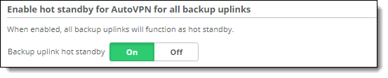
3. Click On or Off next to Backup uplink hot standby.
When you turn hot standby from off to on for SteelHead SD appliances and SDI-2030 gateways, the uplinks will go offline momentarily and then come back online. This is expected behavior.
Configuring the date and time
You can specify the local Network Time Protocol (NTP) servers of your choice, one per line. We recommend that you configure your own internal NTP servers; however, you can leave the field blank to use these default Riverbed-provided NTP servers:
0.ocedo.pool.ntp.org
1.ocedo.pool.ntp.org
2.ocedo.pool.ntp.org
3.ocedo.pool.ntp.org
To configure NTP servers
1. Choose Organization and select an organization.
2. Select the Networking Defaults tab.
3. Under NTP settings, specify the NTP servers of your choice, one per line.
4. Click Submit.
Deleting an organization
To delete an organization
1. Choose Organization and select an organization.
2. From the Actions menu, choose Delete this organization.
If the organization is connected to XMS-Cloud, a message tells you that you can’t delete it. After disconnecting the organization from XMS-Cloud, repeat this procedure. For details, see
Wi-Fi Manager.
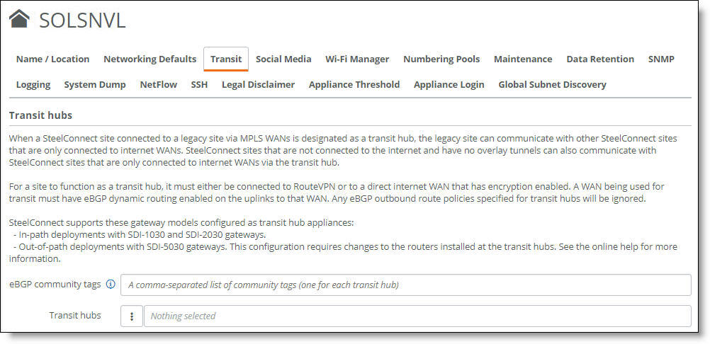
Transit
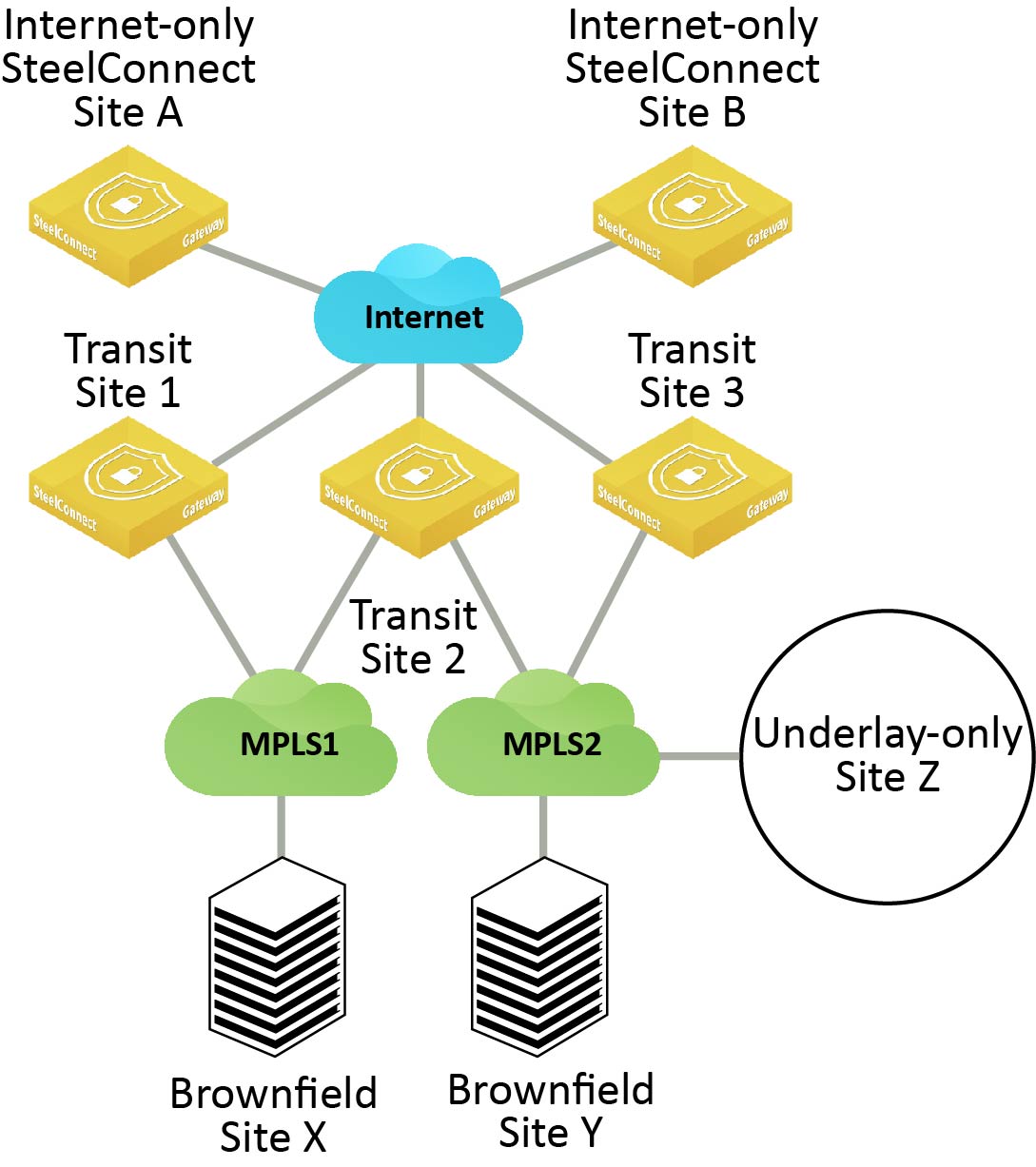
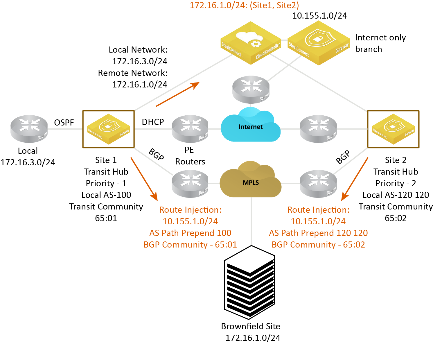
This tab connects two sites in an organization to a transit hub. A transit hub configuration eases the migration to a SteelConnect SD-WAN by providing a communication method between branch sites for these use cases:
•An MPLS-connected legacy site (also known as a non-SteelConnect site or brownfield site) can communicate with a SteelConnect site that is connected to an internet-only WAN by overlay tunnels to one or more transit hub sites. The transit hub site announces the legacy site to the SD-WAN controller as a remote site.
•Provide connection between an underlay-only SteelConnect site and internet-only SteelConnect site.
Transit tab
Transit hub routing shows two internet-only SteelConnect branch sites and an underlay-only SteelConnect site that would typically not be able to connect to the existing legacy sites without a common hub to act as a transit node between the branch sites. After configuring the data center (Transit Site 2 in
Transit hub routing) as a transit hub, traffic can move between the SteelConnect branch sites and the legacy site through the common hub. For the sites that are internet-only connected, all of the remote zone prefixes on their networks will automatically be advertised through BGP at the main data center. Sites that are still on traditional routers and haven’t been migrated to SteelConnect receive the remote zone advertisements from the data center (Transit Site 2 in
Transit hub routing).
Transit hub routing
Transit hub requirements
Before configuring a transit hub, check these requirements:
•The site must be connected to a private MPLS WAN. The private WAN can either be connected to RouteVPN or to a direct internet WAN with encryption enabled.
•A private MPLS WAN connected to a transit site must have eBGP dynamic routing enabled on the uplinks to that WAN.
•SteelConnect underlay-only sites connected to a private WAN (MPLS) with no encryption must have internet breakout configured on the MPLS WAN or an internet uplink that is used primarily for internet-bound underlay traffic.
•SteelConnect underlay-only sites that have one or more uplinks to an internet or direct internet WAN must have AutoVPN disabled on those uplinks. For details on disabling AutoVPN for an uplink, see
Turning off AutoVPN for an uplink.
Supported deployments
SteelConnect supports these gateway models configured as transit hub appliances:
•In-path SteelConnect deployments with SDI-1030 and SDI-2030 gateways.
•Out-of-path SteelConnect deployments with SDI-5030 gateways. This configuration requires changes to the routers installed at the transit hubs. For details, see
Out-of-path deployment considerations.
While the SDI-130, SDI-330, and SDI-1030 gateways support the traditional transit for internet-only branches use case as edge devices, these models aren’t supported as transit hub appliances.
SteelConnect doesn’t support transit between two MPLS WANs.
If a dual-connected SteelConnect site loses MPLS connectivity, it will not be treated as an internet-only site.
Configuring transit hub routing
A transit hub site is configured at the organization level.
To configure transit hub routing
1. Choose Organization and select an organization.
2. Select the Transit tab.
Transit tab for an organization
3. Specify a comma-separated list of up to five unique community names. A community name identifies the set of incoming routes injected for SteelConnect sites with internet-only connectivity. Each transit hub site must have one community name. Specify a community name in the format AA:NN or a number between 1 and 65535.
4. Next to transit hubs, click the search selector.
Click the search selector
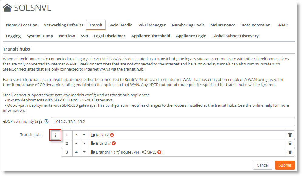
After clicking the search selector, a site list appears. Select the site that will provide transit for all MPLS WANs it is connected to. The first site selected has the highest preference and is assigned as the primary, active site.
A red x appears next to any site that is ineligible for use as a transit hub. Mouse over the red x to view the reason why the site can’t be used as a transit hub. Click the trash can icon to remove the site from the list.
Mouse over to view more information
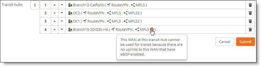
When you select a site that uses a WAN without a service type definition, a message tells you to select a service type for the WAN. To see if the WAN has a service type definition, choose Network Design > WANs. Look for a service type under Service Type in the WAN list. If no service type appears for the WAN, select the WAN, and select a service type from the drop-down list.
After a site is placed on the transit hub list, it disappears from the search selector’s list of sites, because it can’t be reused.
The number of transit sites selected must be less than or equal to the number of comma-separated community tags.
5. For redundancy, select one or more backup sites. Take care when selecting the sites, as site preference is based on the position of the individual sites in the transit hub list from top to bottom. The first site selected has the highest preference, the second site selected has the second highest preference, and so on.
Traffic for the sites will be shifted from the primary site to the backup site if the primary site fails. Both the primary site and the backup sites must have eBGP dynamic routing enabled on the uplinks to this WAN.
You can select up to five sites for a total of one primary, active site and four backup sites. The sites are deployed in active and backup mode. The first site in the list is the primary, active site, and the following sites in the list provide backup.
–The first site in the list and the other sites must deploy the same hardware to provide equal sizing capacity for backup traffic processing in the event of a site failover.
When selecting a site’s preference, take care to align the deployment with the underlay routing configuration to ensure a symmetric traffic flow.
–To change the site preference order, click the up and down arrows.
–To remove a site from the list, click the trash can icon. When a transit site is removed, transit is disabled on the site and all the routes injected by the site are withdrawn.
–The transit site preference overrides path preference when traffic moves to a backup site only when the primary (or active) site is completely unreachable. For details on path preference, see
Directing traffic using traffic rules.
–Disabling eBGP on a transit hub disables transit functionality and the injected routes are withdrawn.
6. Click Submit.
Controller computes all legacy and remote subnets
The transit sites start reporting all underlay routes learned through WAN uplinks to the SD-WAN controller.
All SteelConnect sites report their local sites to the SD-WAN controller.
The SD-WAN controller computes all legacy subnets from the local subnets reported by all SteelConnect sites and the remote subnets reported by the transit sites.
How does the MPLS underlay determine the path priority when the transit sites report the same internet-only prefix?
The transit sites inject the internet-only branch subnets with a cost and then stamp the subnets with the BGP community tag. The cost and the community order are determined based on the transit site order:
•The transit site with the highest preference in the list prepends the AS path once, which results in a route with the shortest AS path. This causes its route advertisement to win over any preexisting, longer path advertisements because it has an AS length of two.
•The next preferred transit site prepends the AS path twice, and so on. If there are five sites in the list, the fifth site prepends the AS path five times.
Controller cost computation depends on site preference
The SD-WAN controller programs a list of overlay routes, giving priority to the legacy sites based on the transit site preference for all internet-only sites.
The transit site retracts the internet-only branch subnets if the tunnel is down between the transit site and the internet-only SteelConnect site. The next transit site in the list takes over as a transit hub.
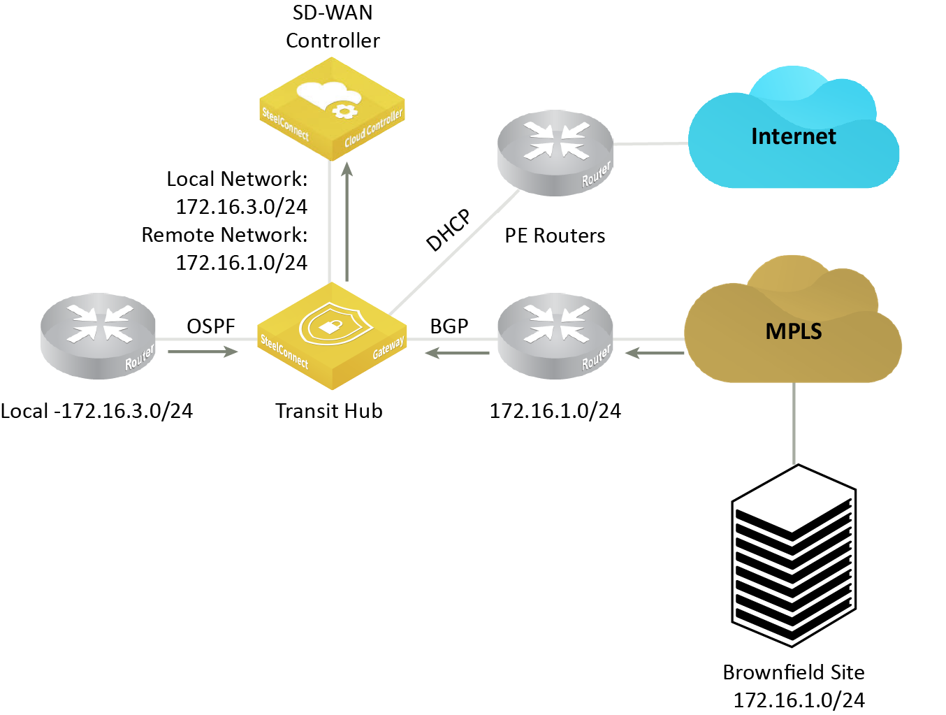
Out-of-path deployment considerations
Because SDI-5030 gateways are deployed out of path, the CE router needs to perform the AS path prepending according to the transit site priority. The SDI-5030 gateway’s BGP peer is the MPLS router. The BGP peer does the AS path prepending count that corresponds to the priority of the transit site before redistributing the route into the MPLS PE BGP peer.
The SDI-5030 gateway’s BGP peer and the MPLS CE router has iBGP between them. The SDI-5030 gateway’s BGP peer redistributes routes with the transit community into the iBGP using the community tag that corresponds to the transit site community.
The MPLS router redistributes into the MPLS PE BGP peer all routes matching the tag with the AS tag prepend count that corresponds to the site priority.
Out-of-path deployment requiring CE router configuration
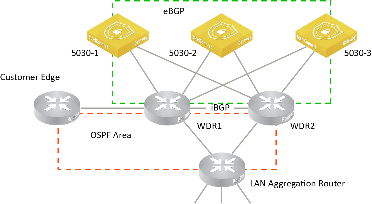
CE router configuration example
This section illustrates the CE router configuration for a deployment with these requirements:
Hub priority | BGP community tag | Site |
P1 | 61:01 | Headquarters site using SDI-5030 gateways |
P2 | 61:02 | Branch site 1 |
P3 | 61:03 | Branch site 2 |
P4 | 61:04 | Branch site 3 |
P5 | 61:05 | Branch site 4 |
Here is the CE router configuration, assuming the router is an AS 200:
ip community-list standard trans_com1 permit 61:01
ip community-list standard trans_com2 permit 61:02
ip community-list standard trans_com3 permit 61:03
ip community-list standard trans_com4 permit 61:04
ip community-list standard trans_com5 permit 61:05
route-map prepend_x permit 1
match community trans_com1
set as-path prepend 200
!
route-map prepend_x permit 2
match community trans_com2
set as-path prepend 200 200
!
route-map prepend_x permit 3
match community trans_com3
set as-path prepend 200 200 200
!
route-map prepend_x permit 4
match community trans_com4
set-as-path prepend 200 200 200 200
!
route-map prepend_x permit 5
match community trans_com5
set-as-path prepend 200 200 200 200 200
!
router bgp 200
neighbor 10.157.3.1 route-map prepend_x out
Viewing the advertised legacy routes
You can monitor the internet-only SteelConnect site prefixes injected by the transit hubs in SCM.
To view the advertised network routes
1. Choose Health Check > Routing Tables.
2. Select the BGP tab.
BGP learned and advertised routes
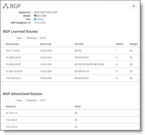
The overlay routes from the internet-only site to the transit hub display the destination network address as the legacy site address. The legacy masks are included with all routes reported by the transit hub and aren’t classified separately.
Social Media
This tab configures guest access using a social media app. For details, see
Registering guest devices using social media without XMS-Cloud.
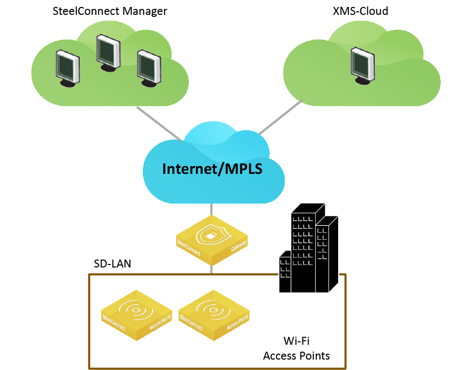
Wi-Fi Manager
This tab enables or disables the Xirrus Management System - Cloud (XMS-Cloud), for wireless access points. XMS-Cloud provides zero-touch activation and automated software upgrades for newly deployed access points. Advanced management includes features such as reporting, upgrades, configuration management, network status, guest and employee or student access, and control of application use at the network edge.
Xirrus XMS-Cloud and SCM work together to manage access points
Each SCM organization needs to be mapped to an XMS-Cloud domain before you can manage the access points through SCM for an organization. A domain is the XMS-Cloud equivalent of an SCM organization. A dialog is presented after you log in to XMS-Cloud that provides a way to associate an XMS-Cloud domain with an SCM organization.
For more details on domains, see the XMS-Cloud online help.
Before accessing XMS-Cloud, you’ll need XMS account credentials to log in.
To log in to XMS-Cloud through SCM
1. Choose Organization and select an organization.
2. Select the Wi-Fi Manager tab.
3. Click Wi-Fi Manager.
4. Type your XMS credentials required to administer the XMS domain: username and password.
5. Click Log In.
After logging in, you’re presented with a dialog to link the SCM organization to an XMS-Cloud domain. The dialog displays all XMS domains you are administering outside of SCM using XMS-Cloud. Associating an SCM organization with an XMS domain is as simple as connecting to the domain.
Connecting an SCM organization with the Riverbed XMS-Cloud Manager will give you integrated manageability for Riverbed SD-WAN products and the Xirrus Wi-Fi access points from SCM. Riverbed AP models SDI-AP3, SDI-AP5, SDI-AP5r and the integrated AP in the SDI-130W cannot be managed concurrently with the Xirrus APs. After the connection between SCM and XMS is made, all configuration for legacy SDI APs will be lost. Proceed ONLY when you have deployed the new Riverbed Xirrus access points and no longer require management for the legacy access point models. Until then, continue to manage Xirrus APs through XMS-Cloud without connecting to SCM.
6. In the Link Domain dialog, select an XMS domain to link to the SCM organization.
7. Click Submit.
SCM discovers all of the access points that are part of the XMS domain and are now linked to the SCM organization. It adds the access points to the organization.
8. Repeat
Step 1 through
Step 7 for each organization you want to link to an XMS-Cloud domain.
To view the access points
•Choose Appliances > Overview.
The XMS access points appear along with all other appliances in the organization.
To assign an access point to a site
1. Choose Appliances > Overview.
2. Select the access point.
3. Select the Location tab.
4. Select a site from the drop-down list.
5. Specify a detailed location for the access point using the Location field. Setting the location associates the access point with its location wherever it is referenced on various SCM pages.
6. Click Submit.
To return to XMS-Cloud, click Wi-Fi Manager. In XMS-Cloud, you can view a guided tour to get started and view online help.
To access the XMS-Cloud online help
•In XMS-Cloud, click the question mark (?) icon in the upper-right corner.
To disconnect from XMS-Cloud
1. Choose Organization and select an organization.
2. Select the Wi-Fi Manager tab.
3. Click Wi-Fi Manager.
4. Click Disconnect.
A dialog tells you that disconnecting the domain link will delete any Wi-Fi Manager appliances and portals in this organization.
5. Click Confirm.
6. Type your XMS credentials: username and password.
7. Click Submit.
Numbering Pools
When SCM creates new zones, it uses the default zone numbering specified on the Numbering Pools tab for VLANs, IPv4, and IPv6 addressing. These are global pool settings used as the base identifiers throughout the organization. Optionally, you can manually configure the numbering for each zone. A simple method is to assign a 10.x.0.0/16 network such as 10.1.0.0/16, which every zone created will then pull an IP address from.
The default numbers are:
•VLAN pool base: 1000
•IPv4 network pool: 172.16.0.0/12
•IPv6 ULA network pool: fd00:ced0:ced0::/48
Both IPv4 and IPv6 addresses come from finite pools of numbers. Don’t create a zone with a subnet the size of the full IP address pool, because doing so can exhaust the pool. After the pool is exhausted, SteelConnect is unable to create the zones with the allocated subnets.
To manually configure the numbering pools
1. Choose Organization and select the Numbering Pools tab.
2. Change the default IP addresses or VLAN pool base.
3. Click Submit.
Changes to the numbering pools apply to new zones only; they don’t affect existing zones.
You can also configure the pool settings when you create a zone. For details, see
Zones within a site.
Maintenance
This tab controls the firmware upgrade process for an organization. A Riverbed appliance simply needs to be connected and registered, and the upgrade happens automatically when a new version of the firmware is available (unless you reschedule the upgrade or an upgrade schedule is customized for an organization within the realm). For details, see
Upgrade overview.
An organization’s maintenance policy overrides the realm’s maintenance policy.
Data Retention
This tab specifies how long SCM retains its traffic data history and unregistered device information for an organization. The maximum number of days is 366. The default setting for traffic history is 14 days and the default setting for unregistered devices is 7 days.
To change the amount of time SCM retains data
1. Choose Organization.
2. Select the Data Retention tab.
3. Change the number of days for traffic history, unregistered devices, or both.
4. Click Submit.
SNMP, Logging, System Dump, and NetFlow
Legal Disclaimer
This tab adds a predefined legal disclaimer that appears each time a user logs in to SCM. For example, “This computer system is the private property of its owner, whether individual, corporate, or government. It is for authorized use only.”
Appliance Thresholds
This tab sets thresholds to measure appliance health. For each appliance type, you can set a threshold limit for CPU usage, number of connections, available memory, transmitted (TX) and received (RX) traffic by port, and the time, in minutes, used to calculate measurements. The default threshold measurement is five minutes.
As long as the thresholds are not exceeded, the appliance is considered healthy. Appliances periodically send resource utilization data and use the threshold settings to generate and report events in the Health Check page whenever a threshold is exceeded. For details, see
Getting a summary of system health.
Appliance Login
This tab sets a login password required on all appliances in an organization for root access. We strongly recommend that you use an appliance console login password. The password must be a minimum of six characters. Leave the login password field blank and click Submit to generate a random console appliance password.
Global Subnet Discovery
This tab applies to all sites with a SteelHead SD appliance. SteelHead SD provides the ability to discover all subnets at the organization or site level. For details, see the SteelHead SD User Guide.