Quick Start
Getting started
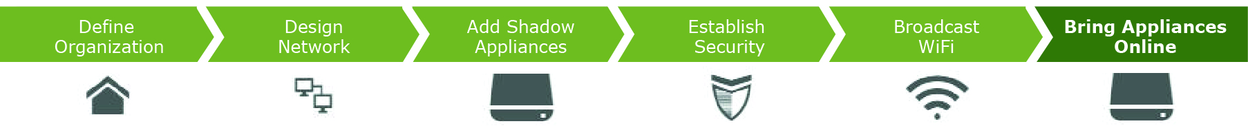
This tutorial describes how to configure a basic network with a single company headquarters in minutes. You'll define an organization, establish network zones (including a guest zone), configure the wireless networks, add users, and then deploy SDI-130 wireless gateways into the sites. You design first and deploy the hardware last.
This tutorial steps you through setting up a basic network and putting it into production. It takes about 20 minutes to complete.
SteelConnect Manager (SCM) uses a single control plane for all sites and provides central policy management for the distributed enterprise. You use it to define the network-wide policy and push the policy to all devices. You complete all configurations through the central console using abstract concepts such as users, applications, sites, and zones.
To begin, log in to SCM. By default, the username is admin and the default password is pppp.
After a successful log in, you're greeted by the dashboard.
A unified view of your organization
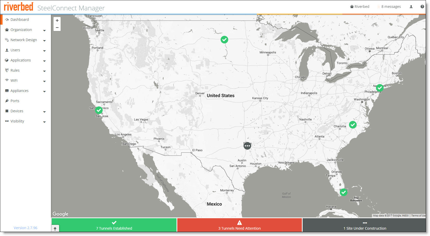
The dashboard shows a visual representation of your organization. For more details, see
Monitoring the Network.
The first step is to define an organization.

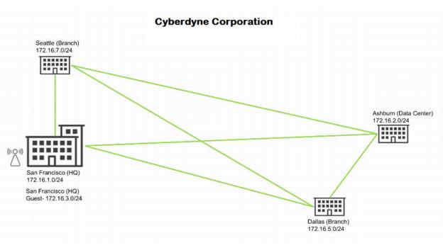
Organization with a headquarters, guest zone, data center, and two branch offices
Defining an organization
SCM uses these terms to describe your company:
•Organization - A company representing an end customer. You can assign administrative rights to individual administrator accounts per organization. You can also manage appliances and licensing per organization.
•Site - A physical location of one or more office buildings, a hosting center, or a cloud location that make up the organization. A site houses a SteelConnect gateway and uses a permanent DNS alias. Every site requires a local network zone and at least one internet uplink. When you create a site, the zone is automatically created and an uplink is automatically created for the internet path.
•Zone - Layer 2 network segments or VLANs within sites that are VLAN-tagged traffic. A zone always has a VLAN tag assigned to it.
SCM is delivered with a default organization. You’ll want to edit the default site.
After adding the company name, you’ll add basic information. You can always change and customize this information later.
To change a company name and location
1. Choose Organization.
2. Change the organization name to Cyberdyne.
3. Click Submit.
4. Under location, type the company headquarters physical address in San Francisco.
5. Click Submit.
The dashboard map updates dynamically to keep an accurate visual overview of your network. You can always refer to the dashboard map as you define your topology to make sure the deployment is accurate.
To add sites
1. Choose Network Design > Sites.
2. Click Add Site(s).
3. Add a site tag: for example, headquarters.
4. Add the site’s location: for example, San Francisco.
5. Type the site’s address, country, and time zone.
6. Click Submit.
After you create the site, it appears on the dashboard map. Repeat steps 2 through 6 to add a site for the data center in Ashburn, and two more sites for branches in Seattle and Dallas.
Designing a network
After you define your organization, you are ready to design a network. You’ll start by editing and creating zones. Zones are Layer 2 network segments (or VLANs within sites) that contain networks and IP addresses. In this tutorial, you’ll change the default zone for the LAN.
To change a zone
1. Choose Network Design > Zones.
2. Select a zone, click Settings, and update the zone name.
3. Select the IP tab, and change the IP address to match your network topology.
In this tutorial, you want this zone to be part of the VPN and to automatically connect your VPN connection using automated VPN. For more details on automated VPN, see
AutoVPN modes.
Regular zones are always part of RouteVPN by default. If you need to remove the RouteVPN membership for a zone, see
To remove a zone from AutoVPN. Guest zones are not included in RouteVPN.
4. Click Submit.
The LAN zone is complete. Next, you’ll create a new zone for guests. Within the guest zone, you can determine how guests can register their devices: using their mobile phone number (SMS), email address, or social media apps (Facebook, Twitter, Google).
To create a guest zone
1. Return to the Zones page and click New Zone.
2. Select the Headquarters (San Francisco) site from the drop-down list.
3. Type Guest to describe the zone.
4. Under guest zone, click On to add some extra intraclient security and isolate the guests from each other.
5. Click Submit.
Two zones are ready for use: one for the corporate LAN in San Francisco and one for the headquarters guests.
Adding shadow appliances
When you add an appliance for future deployment, it’s called a shadow appliance. Shadow appliances are basically cardboard cutouts that you can use to represent what will be a physical appliance after registering it with a serial number. In this tutorial, you’ll add gateways initially and access points later.
1. Choose Appliances > Gateways and click Add appliances.
2. Select Create Shadow Appliance.
3. Select SDI-130 Gateway from the model drop-down list.
4. Choose Headquarters as the site to deploy the shadow gateway.
5. Click Submit.
6. Repeat steps 2 through 6, substituting Ashburn data center as the site instead of Headquarters.
7. Repeat steps 2 through 6 to create gateways for the branch offices in Seattle and Dallas.
After adding the gateways, SCM automatically connects them using AutoVPN to create secure VPN tunnels. Later, you’ll register the gateways to transform them from shadow appliances to physical appliances. For details, see
Adding shadow appliances.
Choose Network Design > Uplinks to see that SCM has automatically assigned uplinks to the new gateways.
Establishing a security policy
Before deploying the hardware, you need to establish a policy that the sites have permission to recognize each other. Because the network is going to be transiting zones, you create an outbound/internal rule within a policy that allows this rule.
To create a policy rule
1. Choose Rules > Outbound/Internal.
2. Click New policy rule.
3. For users/source, select All (excluding guests).
4. Click Allow.
5. Under Applications / Targets, choose Selected zones.
6. Choose all the LANs except the guest LAN in the headquarters to make them accessible from the users/zones.
7. Click On.
The rules match on the source and destination selected.
The next task is to make the zones reachable over WiFi by adding a short name, or service set identifier (SSID), that contains the WiFi definition with authentication options. An SSID distinguishes one wireless network from another. In this tutorial, you’ll create a unified corporate SSID for use at all the sites, and one SSID to allow guests to join the network using a guest portal.
After adding the SSIDs, you can broadcast them by site. Every broadcast can set additional, advanced WiFi options as well as the captive portal. For details, see
How do I use SCM to plan and broadcast WiFi?.
To modify the default SSID
1. Select WiFi.
2. Click New SSID and name it Employees.
By default, an SSID uses WiFi protected access 2 (WPA2) for security. A default SSID also includes a randomly generated password. Changing the default password secures it and makes it easier to remember. Optionally, you can authenticate against RADIUS/NPS servers. See
RADIUS authentication.
3. Select the SSID and change the password.
4. Click Submit.
The SSID for Cyberdyne employees is ready for use. Next, you need to add an SSID for your guests.
To create a guest network
1. Choose WiFi > SSIDs.
2. Click New SSID and name it Guests.
3. Select Open from the security drop-down list to leave this SSID open to the onboarding portal. This selection secures the guest access by requiring them to use SMS or an email authentication to gain access to the guest network.
4. Click Submit.
To add users to the guest network
1. Choose Network Design > Portals.
2. Type the portal name Guest headquarters.
3. Select the portal type Guest Portal - Authenticated.
4. Select email + SMS to turn on the authentication portal so guests are able to use SMS and email authentication to join this network.
5. Click Submit.
The guest network will never be able to connect to the secured corporate VPN.
Now that two SSIDs are defined, you need to broadcast them at your sites. (Again, hardware doesn't come into play yet—you’ll add a gateway later.) You can broadcast SSIDs by site and set advanced WiFi options for each broadcast as well as the captive portal. For details, see
How do I use SCM to plan and broadcast WiFi? You can either set the broadcast channel selection and transmit power automatically or manually per access point.
To broadcast SSIDs
1. Choose WiFi > Broadcasts and click New Broadcast.
2. Select Headquarters (San Francisco).
3. Select the SSID Employees.
4. Select the Headquarters LAN network as the default zone.
5. Click Submit.
6. Under WiFi Broadcasts, click New Broadcast.
7. Select Headquarters (San Francisco).
8. Select the SSID Guests.
9. Select the Headquarters LAN network as the default zone.
10. Click Submit.
11. Select the Guest Portal.
12. Under Portal, select Guest [Guest Portal Authenticated] from the drop-down list.
Broadcasting WiFi wireless radio coverage
First you’ll need to determine how many access points you need. To assist with access point planning, SCM provides an integrated WiFi planner that eliminates expensive planning tools and guesswork. Use the planner to visualize the WiFi coverage in all sites, upload floor plans, and place access point placeholders as required. You can select different coverage-type presets. The WiFi planner will automatically create shadow devices as placeholders that you can turn into real hardware deployments later.
We recommend using the Chrome browser for the best WiFi planning experience.
The WiFi planning tool assumes a barrier-free wireless radio signal coverage.
To plan the WiFi coverage for a site
1. Select Planning.
2. Click New Plan.
3. Select the headquarters site.
4. Type a name for the plan.
5. Select a WiFi profile to influence the recommended access point placement and range.
6. Click Upload Plan or Draw Plan.
To upload a predefined plan, choose the filename and click Open.
7. Click Submit.
The next task is to set the general building dimensions to help define the signal strength and ranges.
To set the building dimensions
1. Click Set Scale.
2. Click the plan, expand an item in the drawing, and set the scale. For example, if you know one wall of your building is 26 feet long, you can set the scale with this wall to 26 feet.
To add access points
1. Open the WiFi planner.
2. Click Create New AP3 (or AP5 or AP5r).
An access point icon appears on the plan, surrounded by a shaded transmit power area.
3. Select 2.4 or 5 GHz.
4. Move the access point to the desired location in the plan.
5. Type a name for the location.
6. Use the slider to adjust the transmit area.
7. Repeat steps 2 through 6 to add more access points, making sure they have the correct placement, amount of channel separation, and transmit power.
8. To avoid overlap between access points, either right-click the access point and select another channel from the channel drop-down list or use the channel auto select (the default setting).
9. Adjust the transmit area and placement of the access point as needed.
10. Click Save.
Because the WiFi planner is integrated in SCM, it uses the concept of shadow appliances for the access points. When you add an access point for future deployment, it’s called a shadow access point. Shadow access points are basically cardboard cutouts that you can use to represent what will be a physical access point.
To view the access points
•Select Appliances > Access Points.
The access points appear with a status of Shadow.
Enabling appliances
SteelConnect Manager stores all configurations, including your existing and future plans. This means you can either add an appliance when you physically have it, or you can preplan and configure an appliance for the future and then later drop the physical appliance into the topology with no further configuration needed.
In SCM, an appliance can be an SD-WAN gateway, an Ethernet switch, or a WiFi access point.
When you add an appliance for future deployment, it’s called a shadow appliance. Shadow appliances are basically cardboard cutouts that you can use to represent what will be a physical appliance after registering it with a serial number.
Now you have shadow appliances deployed, zones created, and a WiFi network that is set up and broadcasting SSIDs. The next task is to register the physical devices to transform them from shadow appliances into physical appliances.
To register a hardware appliance
1. Select the shadow appliance, and choose Actions > Register hardware.
2. The appliance is shipped with a label that has the SteelConnect serial number. Find that serial number on the appliance and type it here.
SteelConnect gateway serial number location
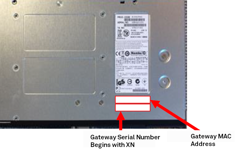
To help you identify an appliance without unmounting it, unregistered appliances with an Organic LED (OLED) display (Gateway 330, Switch S24, and Switch S48) display their serial number in the screen until you register the appliance with SCM.
3. Repeat these steps to register the other appliances.
The provisioning server hands off the appliance when it connects into the particular organization and site. It gives the appliance its configuration, brings it online, performs all firmware upgrades, and realizes your design on the appliance in the real world.
This automatic provisioning makes the appliances easily replaceable, if necessary.
All internet connections, or uplinks, are automatically created when you set up your sites. By default, all uplinks use DHCP; however, SteelConnect also supports static IPs and PPPoE with authentication. For details, see
Creating uplinks.
A complete mesh overlay connects across all sites and shares all networks that are involved with RouteVPN using full permissions.
After AutoVPN establishes the tunnels, you can view the dashboard map to see a visible representation of the network. Click a site marker to verify that the locations are completely connected with a full-mesh VPN. SCM displays the established connections as green lines between the sites. The lines change to red if the tunnel switches to offline.
For troubleshooting, see
Provisioning.
Configuring remote employee access to the corporate LAN
This section steps through the optional procedure of setting up a home office for a CEO that has access to the corporate LAN. When finished, your configuration will reflect
Organization with a home office added to the corporate network.
Organization with a home office added to the corporate network
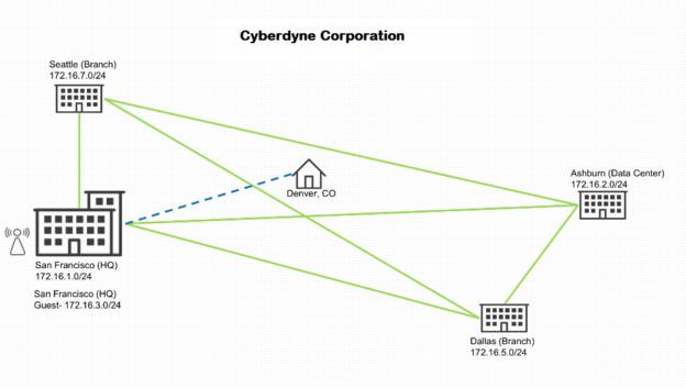
You’ll start by creating a unique site that isn’t part of a dedicated zone shared with the rest of the company. Instead, the new home office site will use an IP address on the headquarters network as though the CEO were working in the building.
To provide the CEO access to the corporate LAN from home
1. Choose Network Design > Sites.
2. Click Add a Site.
3. Type a site tag to give the site a name: for example, CEOSite.
4. Type a site name that describes the site: for example, CEO.
5. Type the CEO’s home site location: for example, Denver.
6. Type the site’s address, country, and time zone.
7. Click Submit. SCM automatically creates a zone for the site.
8. Choose Network Design > Zones.
9. Select the zone CEOSite, select the IP tab, and change the IP address to match the CEO’s local internet connection.
10. Click Submit.
11. Because the CEO’s home office will use an access point instead of a gateway, select the Gateways tab and select Manual to disable automatic gateway configuration.
12. Choose Uplinks and choose CEOSite.
13. Select the Settings tab and rename the uplink to CEO-Uplink.
14. Choose WiFi > Broadcasts and click New Broadcast.
15. Select CEOSite (CEO).
16. Select the SSID Employees.
17. Select the headquarters LAN as the default zone.
18. Click Submit.
When the CEO joins the network from home, the CEO is assigned an IP address on the corporate LAN. You don’t need to create a security policy because the home office isn’t transiting sites.
19. Choose Appliances and click Add appliances.
20. Select Create Shadow Appliance.
21. Select an Access Point.
22. Choose CEOSite (CEO) as the site to deploy the access point.
23. Click Submit.
After registering the access point, the CEO joins the corporate LAN from home. For details, see
Adding shadow appliances.
Logging out
To log out of the current session
1. In the upper-right corner click your username to open the drop-down menu.
2. Click Logout.