Policy-Based Routing Virtual In-Path Deployments
This chapter describes the basic steps for policy-based routing (PBR) network deployments and how to configure PBR to redirect traffic to a SteelHead or group of SteelHeads.
This chapter includes the following sections:
For information about the factors you must consider before you design and deploy the SteelHead in a network environment, see
Choosing the Right SteelHead Model.
Overview of PBR
PBR is a packet redirection mechanism that allows you to define policies to route packets instead of relying on routing protocols. PBR redirects packets to SteelHeads that are in a virtual in-path deployment. This section includes the following topics:
You define PBR policies on your router for switching packets. PBR policies can be based on identifiers available in access lists, such as the source IP address, destination IP address, protocol, source port, or destination port.
When a PBR-enabled router interface receives a packet that matches a defined policy, PBR switches the packet according to the rule defined for the policy. If a packet does not match a defined policy, the packet is routed by the IP address specified in the routing table entry that most closely matches the destination address.
Important: To avoid an infinite loop, PBR must be enabled on the router interfaces where client traffic arrives and disabled on the router interface that is connected to the SteelHead.
PBR is enabled as a global configuration and applied on an interface basis. Each virtual in-path interface can be used simultaneously for receiving traffic redirected through PBR; physically, the WAN port is cabled and used to receive the redirected traffic.
The SteelHead that intercepts traffic redirected by PBR is configured with both in-path and virtual in-path support enabled.
PBR Failover and Cisco Discovery Protocol
A major issue with PBR is that it can cause a traffic black hole; that is, it drops all packets to a destination if the device it is redirecting to fails. You can avoid the traffic black holes by enabling PBR to track whether or not the PBR next-hop IP address is available. You configure the PBR-enabled router to use the Cisco Discovery Protocol (CDP). CDP is a protocol used by Cisco routers and switches to obtain information such as neighbor IP addresses, models, and IOS versions. The protocol runs at the OSI Layer 2 using the 802.3 Ethernet frame. You also enable CDP on the SteelHead.
CDP must be enabled on the SteelHead that is used in the PBR deployment. You enable CDP using the in-path cdp enable command. For details, see the Riverbed Command-Line Interface Reference Manual.
CDP enables SteelHeads to provide automatic failover for PBR deployments. You configure the SteelHead to send out CDP frames. The PBR-enabled router uses these frames to determine whether the SteelHead is operational. If the SteelHead is not operational, the PBR-enabled router stops receiving the CDP frames, and PBR stops switching traffic to the SteelHead.
The SteelHead must be physically connected to the PBR-enabled router for CDP to send frames. If a switch or other Layer-2 device is located between the PBR-enabled router and the SteelHead, CDP frames cannot reach the router. If the CDP frames do not reach the router, the router assumes that the SteelHead is not operational.
CDP is not supported as a failover mechanism on all Cisco platforms. For information about whether your Cisco device supports this feature, refer to your router documentation.
To enable CDP on the SteelHead
• Connect to the SteelHead CLI and enter the following commands:
enable
configure terminal
in-path cdp enable
write memory
restart
Note: You must save your changes and restart the SteelHead for your changes to take effect.
To enable CDP failover on the router
1. On the PBR router, at the system prompt, use the set ip next-hop verify-availability command. For details, refer to your router documentation.
ICMP and HTTP GET can both also be used to track whether or not the PBR next-hop IP address is available.
When you configure the set ip next-hop verify-availability Cisco router command, PBR sends a packet in the following manner:
2. PBR checks the CDP neighbor table to verify that the PBR next-hop IP address is available.
3. If the PBR next-hop IP address is available, PBR sends an ARP request for the address, obtains an answer for it, and redirects traffic to the PBR next-hop IP address (the SteelHead).
4. PBR continues sending traffic to the next-hop IP address as long as the ARP requests obtain answers for the next-hop IP address.
5. If the ARP request fails to obtain an answer, PBR checks the CDP table. If there is no entry in the CDP table, PBR stops using the route map to send traffic. This verification provides a failover mechanism.
A Cisco 6500 router and switch combination that is configured in hybrid mode does not support PBR with CDP. A hybrid setup requires that you use a native setup for PBR with CDP to work. This configuration fails because all routing is performed on the Multilayer Switch Feature Card (MSFC). The MSFC is treated as an independent system in a hybrid setup. Therefore, when you run the show cdp neighbors Cisco command on the MSFC, it displays the supervisor card as its only neighbor. PBR does not detect the devices that are connected to the switch ports. As a result, PBR does not redirect any traffic for route maps that use the set ip next-hop verify-availability Cisco command. For details, refer to your router documentation.
Alternate PBR Failover Mechanisms
Several other PBR failover methods exist:
• Object tracking
• Dedicated Layer-3 subnet
• Scriptable programming language
Object tracking is a Cisco IOS feature. The Cisco router generates synthetic traffic through a variety of methods (HTTP GET, ping, TCP connect, and so on) to determine if the SteelHead interface is available. If the SteelHead interface is declared unavailable by object tracking, then the router moves to the next SteelHead, or routes the packet normally.
For more information about object tracking, see
Configuring a SteelHead with Object Tracking.
You can deploy the SteelHead on a dedicated Layer-3 subnet. A dedicated Layer-3 subnet provides a simple approach to failover without incurring additional CPU load on the Layer-3 device. The SteelHead must be the only device in the subnet and connected to the Layer-3 device. If the SteelHead becomes unavailable, the dedicated Layer-3 subnet disappears from the routing table and the packet is routed normally. When all the interfaces for a VLAN or subnet do not connect to a Layer-3 switch, the corresponding route is withdrawn from the routing table and the policy statement is bypassed.
If you use a Layer-3 switch, there cannot be another interface in the WAN optimization VLAN, including 802.1Q trunks.
Some Layer-3 devices include a scriptable programming language: for example, Cisco Embedded Event Manager. You can use a scriptable programing language to actively detect an event and initiate a series of CLI commands to disable PBR. If an event occurs indicating the SteelHead has failed, the PBR configuration is automatically removed. If the event reverses, the PBR configuration is automatically reapplied.
Connecting the SteelHead in a PBR Deployment
You can use several types of Ethernet cables to attach to the SteelHead in PBR deployments:
• A straight-through cable to the primary interface. You use this connection to manage the SteelHead, reaching it through HTTPS or SSH.
• A straight-through cable to the WAN0_0 interface if you are connecting to a switch.
• A crossover cable to the WAN0_0 interface if you are connecting to a router. You assign an IP address to the in-path interface; this is the IP address that you redirect traffic to (the target of the router PBR rule).
Configuring PBR
This section describes how to configure PBR and provides example deployments. This section includes the following topics:
Overview of Configuring PBR
You can use access lists to specify which traffic is redirected to the SteelHead. Traffic that is not specified in the access list is switched normally. If you do not have an access list, or if your access list is not correctly configured in the route map, traffic is not redirected.
For information about access lists, see
Configuring Access Control Lists.
Important: Riverbed recommends that you define a policy based on the source or destination IP address rather than on the TCP source or destination ports, because certain protocols use dynamic ports instead of fixed ones.
Configuring a SteelHead to Directly Connect to the Router
Figure: SteelHead Directly Connected to the Router shows a SteelHead deployment in which the SteelHead is configured with PBR and is directly connected to the router.
Figure: SteelHead Directly Connected to the Router
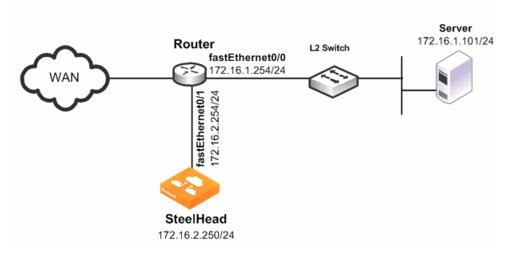
In this example:
• The router fastEthernet0/0 interface is attached to the Layer-2 switch.
• The router fastEthernet0/1 interface is attached to the SteelHead.
• A single SteelHead is configured. You can add more SteelHeads using the same method as for the first SteelHead.
Although the primary interface is not included in this example, Riverbed recommends, as a best practice, that you connect the primary interface for management purposes.
You must configure subnet side rules when you use VSP in a virtual in-path deployment. To configure subnet side rules, choose Networking > Networking: Subnet Side Rules. VSP is enabled by default in the SteelHead EX series.
For information about configuring the primary interface, see the SteelHead Management Console User’s Guide.
To configure a SteelHead with PBR connected directly to the router
1. Connect to the SteelHead CLI and enter the following commands:
enable
configure terminal
in-path enable
in-path oop enable
interface in-path0_0 ip address 172.16.2.250/24
ip in-path-gateway inpath0_0 172.16.2.254
write memory
restart
You must save your changes or they are lost upon reboot. Restart the optimization service for the changes to take effect.
2. On the PBR router, at the system prompt, enter the following commands:
enable
configure terminal
route-map riverbed
match ip address 101
set ip next-hop 172.16.2.250
exit
ip access-list extended 101
permit tcp any 172.16.1.101 0.0.0.0
permit tcp 172.16.1.101 0.0.0.0 any
exit
interface fa0/0
ip policy route-map riverbed
interface S0/0
ip policy route-map riverbed
exit
exit
write memory
Enter one configuration command per line. Press Ctrl+Z to end the configuration.
Configuring a SteelHead to Connect to a Layer-2 Switch
Figure: SteelHead Connected to a Layer-2 Switch with a VLAN shows a SteelHead deployment in which the SteelHead is configured with PBR and is directly connected to the router through a switch. This deployment also has a trunk between the switch and the router.
Figure: SteelHead Connected to a Layer-2 Switch with a VLAN
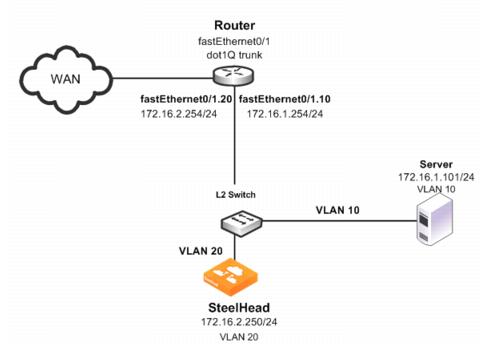
In this example:
• The switch logically separates the server and the SteelHead by placing:
– the server on VLAN 10.
– the SteelHead on VLAN 20.
• The router fastEthernet0/1 interface is attached to the Layer-2 switch.
• The router performs inter-VLAN routing; that is, the router switches packets from one VLAN to the other.
• The link between the router and the switch is configured as a dot1Q trunk to transport traffic from multiple VLANs.
Although the primary interface is not included in this example, Riverbed recommends that you connect the primary interface for management purposes.
For information about configuring the primary interface, see the SteelHead Management Console User’s Guide.
To configure a SteelHead with PBR to a connected Layer-2 switch with a VLAN to the router
1. Connect to the SteelHead CLI and enter the following commands:
enable
configure terminal
in-path enable
in-path oop enable
interface in-path0_0 ip address 172.16.2.250/24
ip in-path-gateway inpath0_0 172.16.2.254
write memory
restart
You must save your changes or they are lost upon reboot. Restart the optimization service for the changes to take effect.
2. On the PBR router, at the system prompt, enter the following commands:
enable
configure terminal
route-map riverbed
match ip address 101
set ip next-hop 172.16.2.250
exit
ip access-list extended 101
permit tcp any 172.16.1.101 0.0.0.0
permit tcp 172.16.1.101 0.0.0.0 any
exit
interface fa0/1.10
encapsulation dot1Q 10
ip address 172.16.1.254 255.255.255.0
interface fa0/1.20
encapsulation dot1Q 20
ip address 172.16.2.254 255.255.255.0
exit
interface fa0/1.10
ip policy route-map riverbed
interface S0/0
ip policy route-map riverbed
exit
exit
write memory
Tip: Enter one configuration command per line. Press Ctrl+Z to end the configuration.
Note: In this example, assume that both the SteelHead and the server are connected to the correct VLAN. Also assume that these VLAN connections are established through the switch port configuration on the Layer-2 switch.
Configuring a SteelHead to Connect to a Layer-3 Switch
Figure: SteelHead Connected to a Layer-3 Switch shows a SteelHead deployment in which the SteelHead is configured with PBR and is directly connected to a Layer-3 switch.
Figure: SteelHead Connected to a Layer-3 Switch
In this example:
• The Layer-3 switch fastEthernet0/0 interface is attached to the server and is on VLAN 10.
• The Layer-3 switch fastEthernet0/1 interface is attached to the SteelHead and is on VLAN 20.
• A single SteelHead is configured. You can add more appliances using the same method as used for the first SteelHead.
Note: Although the primary interface is not included in this example, Riverbed recommends that you connect the primary interface for management purposes. For information about configuring the primary interface, see the SteelHead Management Console User’s Guide.
To configure a SteelHead with PBR connected directly to a Layer-3 switch
1. Connect to the SteelHead CLI and enter the following commands:
enable
configure terminal
in-path enable
in-path oop enable
in-path cdp enable
interface in-path0_0 ip address 172.16.2.250/24
ip in-path-gateway inpath0_0 172.16.2.254
write memory
restart
You must save your changes or they are lost upon reboot. Restart the optimization service for the changes to take effect.
2. On the Layer-3 switch, at the system prompt, enter the following commands:
enable
configure terminal
route-map riverbed
match ip address 101
set ip next-hop 172.16.2.250
set ip next-hop verify-availability
exit
ip access-list extended 101
permit tcp any 172.16.1.101 0.0.0.0
permit tcp 172.16.1.101 0.0.0.0 any
exit
interface vlan 10
ip address 172.16.1.254 255.255.255.0
ip policy route-map riverbed
interface vlan 20
ip address 172.16.2.254 255.255.255.0
interface vlan 30
ip policy route-map riverbed
exit
exit
write memory
Tip: Enter one configuration commands per line. Press Ctrl+Z to end the configuration.
Configuring a SteelHead with Object Tracking
In an object tracking deployment, the SteelHead is connected to the router, and the router tracks whether the SteelHead is reachable using the Object Tracking feature of Cisco IOS. Object Tracking enables you to use methods such as HTTP GET and ping, to determine whether the PBR next-hop IP address is available.
Object Tracking is not available on all Cisco devices. For information about whether your Cisco device supports this feature, refer to your router documentation.
To configure the SteelHead with object tracking
1. Connect to the SteelHead CLI and enter the following commands:
enable
configure terminal
interface in-path0_0 ip address 172.16.2.2
50/24
ip in-path-gateway inpath0_0 172.16.2.254
in-path enable
in-path oop enable
no interface inpath0_0 fail-to-bypass enable
write memory
2. On the PBR router, at the system prompt, enter the following commands:
enable
configure terminal
ip sla 1
icmp-echo 172.16.2.250
ip sla schedule 1 life forever start-time now
track 101 rtr 1 reachability
route-map riverbed
match ip address 101
set ip next-hop verify-availability 172.16.2.250 10 track 101
exit
ip access-list extended 101
permit tcp any 172.16.1.101 0.0.0.0
permit tcp 172.16.1.101 0.0.0.0 any
exit
interface fa0/0
ip policy route-map riverbed
interface S0/0
ip policy route-map riverbed
exit
exit
write memory
Configuring a SteelHead with Multiple PBR Interfaces
In a deployment that uses multiple PBR interfaces, the SteelHead is connected to two routers, each of which is configured to redirect traffic to a separate interface on the SteelHead. Each router is configured similarly to the single router deployment, except that you specify a next-hop IP address that corresponds to the interface to which the SteelHead connects.
To configure the SteelHead with multiple PBR interfaces
1. Connect to the SteelHead CLI and enter the following commands:
enable
configure terminal
in-path enable
Interface inpath0_1 enable
in-path oop enable
interface in-path0_0 ip address 172.16.2.250/24
ip in-path-gateway inpath0_0 172.16.2.254
interface in-path0_1 ip address 172.16.3.250/24
ip in-path-gateway inpath0_1 172.16.3.254
write memory
restart
You must save your changes or they are lost upon reboot. Restart the optimization service for the changes to take effect.
2. On the first PBR router, at the system prompt, enter the following commands:
enable
configure terminal
route-map riverbed
match ip address 101
set ip next-hop 172.16.2.250
exit
ip access-list extended 101
permit tcp any 172.16.1.101 0.0.0.0
permit tcp 172.16.1.101 0.0.0.0 any
exit
interface fa0/0
ip policy route-map riverbed
interface S0/0
ip policy route-map riverbed
exit
exit
write memory
3. On the second PBR router, at the system prompt, enter the following commands:
enable
configure terminal
route-map riverbed
match ip address 101
set ip next-hop 172.16.3.250
exit
ip access-list extended 101
permit tcp any 172.16.1.101 0.0.0.0
permit tcp 172.16.1.101 0.0.0.0 any
exit
interface fa0/0
ip policy route-map riverbed
interface S0/0
ip policy route-map riverbed
Configuring Multiple SteelHeads to Connect to Multiple Routers
In a PBR environment, you can deploy multiple SteelHeads for optimization redundancy.
Figure: Multiple SteelHeads Directly Connected to Dual Routers shows a SteelHead deployment in which two routers are redirecting packets to two SteelHeads. The SteelHeads are directly connected through multiple interfaces. This deployment provides a high-availability environment—a full-mesh topology between the routers and SteelHeads.
When you deploy multiple SteelHeads, the routers can redirect packets within a TCP connection to different SteelHeads, depending on the router policy. For example, Router A redirects packets to SteelHead A. Following network convergence due to WAN outage packets for this TCP connection, the packets arrive on Router B. Router B has a policy configured to redirect packets to SteelHead B. In this type of environment, Riverbed recommends that you use connection forwarding to ensure packets within a flow are forwarded to the owning SteelHead for optimization.
For more information about connection forwarding, see
Connection Forwarding.
Data store synchronization is not a requirement for SteelHeads in a PBR environment, but it is useful if your design goal is for warm performance after a SteelHead fails. To use data store synchronization, you must meet certain criteria.
For more information about the data store, see
RiOS Data Store Synchronization.
Figure: Multiple SteelHeads Directly Connected to Dual Routers
• Each router fastEthernet2/0 interface is attached to the SteelHead wan0_0 interface using the inpath0_0 IP address.
• Each router fastEthernet3/0 interface is attached to the SteelHead wan0_1 interface using the inpath0_1 IP address.
• Each router withdraws the PBR next-hop statement because the SteelHeads are directly connected (in case a SteelHead interface or appliance fail). You can use other methods for failover, such as CDP, object tracking, or embedded event manager.
• Connection forwarding is enabled to ensure the owning SteelHead receives all packets for the TCP connection.
You can redirect packets to SteelHead interfaces in any order.
Figure: Multiple SteelHeads Directly Connected to Dual Routers shows Router A redirecting packets first to SteelHead A inpath0_0 and then to SteelHead B inpath0_1; and Router B redirecting packets first to SteelHead B inpath0_0 and then SteelHead A inpath0_1. Router A and Router B can redirect to SteelHead A inpath0_0 and inpath0_1 respectively.
This example shows two SteelHeads. You can add more SteelHeads using a similar method as for the first SteelHead.
To configure dual SteelHeads with PBR connected to dual routers
1. Connect to SteelHead A CLI and enter the following commands:
enable
configure terminal
in-path enable
in-path oop enable
interface in-path0_0 ip address 172.16.2.250/24
ip in-path-gateway inpath0_0 172.16.2.254
interface in-path0_1 ip address 172.16.3.250/24
ip in-path-gateway inpath0_1 172.16.3.254
in-path neighbor enable
in-path neighbor multi-interface enable
in-path name SteelHeadB main-ip 172.16.4.250
in-path name SteelHeadB additional-ip 172.16.5.250
in-path neighbor allow-failure
no interface inpath0_0 fail-to-bypass enable
no interface inpath0_1 fail-to-bypass enable
write memory
restart
You must save your changes or they are lost upon reboot. Restart the optimization service for the changes to take effect.
2. Connect to SteelHead B CLI and enter the following commands:
enable
configure terminal
in-path enable
in-path oop enable
interface in-path0_0 ip address 172.16.4.250/24
ip in-path-gateway inpath0_0 172.16.4.254
interface in-path0_1 ip address 172.16.5.250/24
ip in-path-gateway inpath0_1 172.16.5.254
in-path neighbor enable
in-path neighbor multi-interface enable
in-path name SteelHeadA main-ip 172.16.2.250
in-path name SteelHeadA additional-ip 172.16.3.250
in-path neighbor allow-failure
no interface inpath0_0 fail-to-bypass enable
no interface inpath0_1 fail-to-bypass enable
write memory
restart
You must save your changes or they are lost upon reboot. Restart the optimization service for the changes to take effect.
3. On Router A, at the system prompt, enter the following commands:
enable
configure terminal
route-map riverbed
match ip address 101
set ip next-hop 172.16.2.250 172.16.5.250
exit
ip access-list extended 101
permit tcp any 172.16.1.101 0.0.0.0
permit tcp 172.16.1.101 0.0.0.0 any
exit
interface fa2/0
ip address 172.16.2.254 255.255.255.0
interface fa3/0
ip address 172.16.5.254 255.255.255.0
exit
interface fa1/0
ip policy route-map riverbed
interface S0/0
ip policy route-map riverbed
exit
exit
write memory
4. On Router B, at the system prompt, enter the following commands:
enable
configure terminal
route-map riverbed
match ip address 101
set ip next-hop 172.16.4.250 172.16.3.250
exit
ip access-list extended 101
permit tcp any 172.16.1.101 0.0.0.0
permit tcp 172.16.1.101 0.0.0.0 any
exit
interface fa2/0
ip address 172.16.3.254 255.255.255.0
interface fa3/0
ip address 172.16.4.254 255.255.255.0
exit
interface fa1/0
ip policy route-map riverbed
interface S0/0
ip policy route-map riverbed
exit
exit
write memory
Configuring PBR for Load Balancing WAN Circuits
In a network with multiple entry and exit points, you can configure the router and SteelHead to support two goals:
• Support peer affinity so one SteelHead more efficiently optimizes the traffic for a remote peer
• Maintain outbound load balancing by allowing the SteelHeads to use separate WAN circuits to reach the remote sites
Figure: PBR Load Balancing shows all SteelHeads in one subnet. The routers are configured with access control lists (ACLs) to direct traffic from remote peer A to SteelHead A and traffic for remote peer B to SteelHead B. The failover method is object tracking. An optional all-inclusive rule is added to simplify the addition of a new remote site. To support outbound load balancing, each SteelHead uses a different default gateway.
Optimized traffic from SteelHead A reaches the WAN through Router A, and SteelHead B reaches the WAN through router B. Multiple HSRP (MHSRP) allows the routers to present two default gateways for the WAN optimization subnet, at the same time having redundancy in case a WAN circuit fails. Instead of MHSRP, you could use Gateway Load Balancing Protocol (GLBP) or static routes on the SteelHeads. If you use one of these two methods, the SteelHeads are unaware of a WAN circuit outage.
Figure: PBR Load Balancing
In this example:
• Each router fastEthernet2/0 interface and SteelHead wan0_0 interface are attached to same VLAN on the switch.
• Each router uses object tracking to bypass the PBR next-hop statement because the SteelHeads are not directly connected to the router. Embedded event manager is another option.
CDP frames from the SteelHead are consumed by the switch and do not reach the routers. This renders CDP ineffective for failover.
• Packets are redirected to a SteelHead based on remote IP address subnet for peer affinity.
• Multiple HSRP groups are used on the router fastEthernet2/0 interfaces to achieve outbound load balancing on the WAN. (GLBP, or configuring static routes on the SteelHead in-path interface can be used instead of multiple HSRP.)
• Router WAN interfaces are tracked when using HSRP to ensure the router has a path to the remote site.
• Multi-interface is enabled in case another SteelHead interface is connected to another WAN optimization subnet.
Two SteelHeads are configured in this example. You can add more SteelHeads using the same method as used for one of the SteelHeads ensuring policy route statements, any ACLs, and the default gateway align with load balancing and redundancy goals.
To configure PBR appliances in a load-balanced environment
1. Connect to SteelHead A CLI and enter the following commands:
enable
configure terminal
in-path enable
in-path oop enable
interface in-path0_0 ip address 172.16.2.250/24
ip in-path-gateway inpath0_0 172.16.2.254
in-path neighbor enable
in-path neighbor multi-interface enable
in-path name SteelHeadB main-ip 172.16.2.251
in-path neighbor allow-failure
no interface inpath0_0 fail-to-bypass enable
write memory
restart
You must save your changes or they are lost upon reboot. Restart the optimization service for the changes to take effect.
2. Connect to SteelHead B CLI and enter the following commands:
enable
configure terminal
in-path enable
in-path oop enable
interface in-path0_0 ip address 172.16.2.251/24
ip in-path-gateway inpath0_0 172.16.2.253
in-path neighbor enable
in-path neighbor multi-interface enable
in-path name SteelHeadA main-ip 172.16.2.250
in-path neighbor allow-failure
no interface inpath0_0 fail-to-bypass enable
write memory
restart
You must save your changes or they are lost upon reboot. Restart the optimization service for the changes to take effect.
3. On PBR router A, at the system prompt, enter the following commands:
enable
configure terminal
ip access-list extended Remotes-To-A
permit tcp address 10.1.100.0 0.0.0.255 any
permit tcp address any 10.1.100.0 0.0.0.255
exit
ip access-list extended Remotes-To-B
permit tcp address 10.1.200.0 0.0.0.255 any
permit tcp address any 10.1.200.0 0.0.0.255
exit
ip access-list extended Catch-All
permit tcp any 172.16.1.101 0.0.0.0
permit tcp 172.16.1.101 0.0.0.0 any
exit
ip sla 1
icmp-echo 172.16.2.250 source-interface fastEthernet2/0
exit
ip sla schedule 1 life forever start-time now
ip sla 2
icmp-echo 172.16.2.251 source-interface fastEthernet2/0
exit
ip sla schedule 2 life forever start-time now
track 1 ip sla 1 reachability
track 2 ip sla 2 reachability
track 100 interface S0/0 line-protocol
route-map riverbed permit 10
match ip address Remotes-To-A
set ip next-hop verify-availability 172.16.2.250 1 track 1
set ip next-hop verify-availability 172.16.2.251 2 track 2
route-map riverbed permit 20
match ip address Remotes-To-B
set ip next-hop verify-availability 172.16.2.251 1 track 2
set ip next-hop verify-availability 172.16.2.250 2 track 1
route-map riverbed permit 30
match ip address Catch-All
set ip next-hop verify-availability 172.16.2.250 1 track 1
set ip next-hop verify-availability 172.16.2.251 2 track 2
exit
interface fa2/0
ip address 172.16.2.1 255.255.255.0
standby 1 ip 172.16.2.254
standby 1 priority 110
standby 1 preempt
standby 1 track 100 20
standby 2 ip 172.16.2.253
standby 2 preempt
exit
interface fa1/0
ip policy route-map riverbed
interface S0/0
ip policy route-map riverbed
exit
exit
write memory
4. On PBR Router B, at the system prompt, enter the following commands:
enable
configure terminal
ip access-list extended Remotes-To-A
permit tcp address 10.1.100.0 0.0.0.255 any
permit tcp address any 10.1.100.0 0.0.0.255
exit
ip access-list extended Remotes-To-B
permit tcp address 10.1.200.0 0.0.0.255 any
permit tcp address any 10.1.200.0 0.0.0.255
exit
ip access-list extended Catch-All
permit tcp any 172.16.1.101 0.0.0.0
permit tcp 172.16.1.101 0.0.0.0 any
exit
ip sla 1
icmp-echo 172.16.2.250 source-interface fastEthernet2/0
exit
ip sla schedule 1 life forever start-time now
ip sla 2
icmp-echo 172.16.2.251 source-interface fastEthernet2/0
exit
ip sla schedule 2 life forever start-time now
track 1 ip sla 1 reachability
track 2 ip sla 2 reachability
track 100 interface S0/0 line-protocol
route-map riverbed permit 10
match ip address Remotes-To-A
set ip next-hop verify-availability 172.16.2.250 1 track 1
set ip next-hop verify-availability 172.16.2.251 2 track 2
route-map riverbed permit 20
match ip address Remotes-To-B
set ip next-hop verify-availability 172.16.2.251 1 track 2
set ip next-hop verify-availability 172.16.2.250 2 track 1
route-map riverbed permit 30
match ip address Catch-All
set ip next-hop verify-availability 172.16.2.250 1 track 1
set ip next-hop verify-availability 172.16.2.251 2 track 2
exit
interface fa2/0
ip address 172.16.2.2 255.255.255.0
standby 1 ip 172.16.2.254
standby 1 preempt
standby 2 ip 172.16.2.253
standby 2 priority 110
standby 2 preempt
standby 2 track 100 20
exit
interface fa1/0
ip policy route-map riverbed
interface S0/0
ip policy route-map riverbed
exit
exit
write memory
Configuring Local PBR for ICMP Redirection in a Mixed MTU Environment
You can add a Local PBR configuration in addition to the regular PBR configuration discussed in previous sections. You use a Local PBR configuration in environments where ICMP messages generated by the router need special routing configurations: for example, mixed-size maximum transmission unit (MTU) environment with SteelHead full-transparency in-path rules.
In networks that have a mix of MTU interface configurations, path MTU (PMTU) discovery determines the MTU size on the network path between two IP hosts, to avoid IP fragmentation. Network routers send ICMP Fragment needed but do not fragment bit set messages and packets back to the sending host; the host then decreases the segment size and retransmits the segment.
You must forward ICMP packets to the correct host (the client, server, or SteelHead). In some network scenarios, you need a Local PBR configuration to ensure ICMP messages, generated by a router, are redirected out of the same interface of the inbound IP datagram that triggers the ICMP message. Cisco Local PBR is a local policy route map configuration that can achieve this.
Figure: Local PBR Configuration shows an example scenario for which you can configure Local PBR.
Figure: Local PBR Configuration
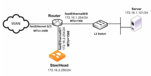
In this example, the:
• router fastEthernet0/0 interface is attached to the layer 2 switch. The MTU is configured for 1500 bytes.
• router fastEthernet0/1 interface is attached to the SteelHead. The MTU is configured for 1500 bytes.
• router fastEthernet 0/2 interface is attached to the WAN. The MTU is configured for 1400 bytes.
• SteelHead is configured to optimize with full transparency.
Without a Local PBR configuration on the router, optimized connections on the SteelHead can attempt to send IP datagrams of 1500 bytes across the WAN. Due to PMTU discovery, the router generates an ICMP fragment needed but do not fragment bit set message.
Because the SteelHead is configured with full transparency, the router forwards the ICMP message back to the server instead of the SteelHead. This results in the server reducing its segment size for the connection, when in fact, the SteelHead must be the one to reduce its segment size. This confusion results in transfer failure.
You can use the following Local PBR configuration on the router to ensure that packets received on fastethernet0/1, and trigger any ICMP message on the router, are forwarded to the SteelHead.
To configure Local PBR on the router
• On the PBR router, at the system prompt, enter the following commands:
Enable
Configure terminal
ip local policy route-map local_pbr_1
access-list 101 permit icmp host 172.16.2.254 any
route-map local_pbr_1 permit 10
match ip address 101
set ip next-hop 172.16.2.250
exit
exit
write memory
Exporting Flow Data and Virtual In-Path Deployments
In virtual in-path deployments, such as PBR, traffic moves in and out of the same WAN0_0 interface. The LAN interface is not used. When the SteelHead exports data to a flow data collector, all traffic has the wan0_0 interface index, making it impossible for an administrator to use the interface index to distinguish between LAN-to-WAN and WAN-to-LAN traffic.
You can configure the fake index feature on your SteelHead to insert the correct interface index before exporting data to a flow data collector.