Virtual In-Path Deployments
This chapter describes virtual in-path deployments and summarizes the basic steps for configuring an in‑path, load-balanced, Layer-4 switch deployment.
This chapter includes the following sections:
This chapter provides the basic steps for configuring one type of virtual in-path deployment. It does not provide detailed procedures for all virtual in-path deployments. Use this chapter as a general guide to virtual in-path deployments.
For information about the factors you must consider before you design and deploy the SteelHead in a network environment, see
Choosing the Right SteelHead Model.
Overview of Virtual In-Path Deployment
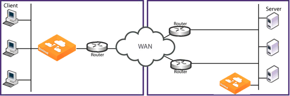
In a virtual in-path deployment, the SteelHead is virtually in the path between clients and servers. Traffic moves in and out of the same WAN interface, and the LAN interface is not used. This deployment differs from a physical in-path deployment in that a packet redirection mechanism directs packets to SteelHeads that are not in the physical path of the client or server.
Figure: Virtual In-Path Deployment on the Server-Side of the Network

Redirection mechanisms include:
• Layer-4 switch - You enable Layer-4 switch (or server load balancer) support when you have multiple SteelHeads in your network to manage large bandwidth requirements.
• Hybrid - In a hybrid deployment, the SteelHead is deployed either in a physical or virtual in-path mode, and it has out-of-path mode enabled. A hybrid deployment is useful in which the SteelHead must be referenced from remote sites as an out-of-path device (for example, to bypass intermediary SteelHeads).
• PBR - PBR enables you to redirect traffic to a SteelHead that is configured as a virtual in-path device. PBR allows you to define policies that override routing behavior. For example, instead of routing a packet based on routing table information, it is routed based on the policy applied to the router. You define policies to redirect traffic to the SteelHead and policies to avoid loop-back.
• WCCP - WCCP was originally implemented on Cisco routers, multilayer switches, and web caches to redirect HTTP requests to local web caches (Version 1). Version 2, which is supported on SteelHeads, can redirect any type of connection from multiple routers to multiple web caches. For example, if you have multiple routers or if there is no in-path place for the SteelHead, you can place the SteelHead in a virtual in-path mode through the router so that they work together.
• Interceptor appliance - The SteelHead Interceptor is a load balancer specifically used to distribute optimized traffic to a local cluster of SteelHeads. The SteelHead Interceptor is SteelHead aware, so it offers several benefits over other clustering techniques like WCCP and PBR. The SteelHead Interceptor is dedicated to redirecting packets for optimized connections to SteelHeads, but it does not perform optimization itself. As a result, you can use the SteelHead Interceptor in extremely demanding network environments with extremely high throughput requirements. For information about the SteelHead Interceptor, see the SteelHead Interceptor Deployment Guide and the SteelHead Interceptor User’s Guide.
For networks that contain firewalls or tunnels (VPN, GRE, IPSec transport mode) between SteelHeads and require manual tuning of the MTU values, see
MTU Sizing.
Configuring an In-Path, Load-Balanced, Layer-4 Switch Deployment
An in-path, load-balanced, Layer-4 switch deployment serves high-traffic environments or environments with large numbers of active TCP connections. It handles failures, scales easily, and supports all protocols.
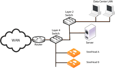
When you configure the SteelHead using a Layer-4 switch, you define the SteelHeads as a pool in which the Layer-4 switch redirects client and server traffic. Only one WAN interface on the SteelHead is connected to the Layer‑4 switch, and the SteelHead is configured to send and receive data through that interface.
Figure: In-Path, Load-Balanced, Layer-4 Switch Deployment shows the server-side of the network where load balancing is required.
Figure: In-Path, Load-Balanced, Layer-4 Switch Deployment

To configure the client-side SteelHead for in-path load-balanced, Layer-4 switch
• Configure the client-side SteelHead as an in-path device. For details, see the SteelHead Installation and Configuration Guide.
To configure the server-side SteelHead for in-path load-balanced, Layer-4 switch
1. Install and power on the SteelHead.
2. Connect to the SteelHead. Make sure you properly connect to the Layer-2 switch, for example:
• On SteelHeadA, plug the straight-through cable into the primary port of the SteelHead and connect it to the LAN-side switch.
• On SteelHeadB, plug the straight-through cable into the primary port of the SteelHead and connect it to the LAN-side switch.
3. Configure the SteelHead in an in-path configuration.
4. Connect the Layer-4 switch to the SteelHead:
• On SteelHeadA, plug the straight-through cable into the WAN port of the SteelHead and the Layer-4 switch.
• On SteelHeadB, plug the straight-through cable into the WAN port of the SteelHead and the Layer-4 switch.
5. Connect to the Management Console.
6. Choose Optimization > Network Services: General Service Settings page and enable Layer-4 switch support. For example, select Enable In-Path Support and select Enable L4/PBR/WCCP Support.
7. Apply and save the new configuration in the Management Console.
8. Configure your Layer-4 switch as instructed by your switch documentation.
9. Choose Administration > Maintenance: Services and restart the optimization service.
10. View performance reports and system logs.
11. Perform the above steps for each SteelHead in the cluster.
Configuring Flow Data Exports in Virtual In-Path Deployments
The SteelHead supports the export of data flows to any compatible flow data collector. During data flow export, the flow data fields provide information such as the interface index that corresponds to the input and output traffic. An administrator can use the interface index to determine how much traffic is flowing from the LAN to the WAN and from the WAN to the LAN.
In virtual in-path deployments, such as the server-side of the network, traffic moves in and out of the same WAN interface; the LAN interface is not used. As a result, when the SteelHead exports data to a flow data collector, all traffic has the WAN interface index. Though it is technically correct for all traffic to have the WAN interface index because the input and output interfaces are the same, this setting makes it impossible for an administrator to use the interface index to distinguish between LAN-to-WAN and WAN-to-LAN traffic.
In RiOS 6.0 or later, the fake index feature is enabled by default if you enable the CascadeFlow export option. Prior to RiOS 6.0, or if you are using standard NetFlow, you can work around this issue by turning on the SteelHead fake index feature, which inserts the correct interface index before exporting data to a flow data collector. The fake index feature works only for optimized traffic, not unoptimized or passed-through traffic.
For information about how to configure a fake index in the CLI in release prior to RiOS 6.0, see the appropriate version of the Riverbed Command-Line Interface Reference Manual or the SteelHead Deployment Guide.
Note: Subnet side rules are necessary for correct unoptimized or passed-through traffic reporting. For details, see the SteelHead Management Console User’s Guide.
For information about exporting flow data, see
Overview of Exporting Flow Data.


