About Managed Appliances
You can manage remote appliances and configure appliance groups under Manage > Topology: Appliances. Appliance groups and policies facilitate centralized configuration, management, and reporting of your Riverbed appliances. For example, at the group level you can apply policies, push configurations, set passwords, and so forth. Appliance groups can be based on location, similarity of features, or whatever criteria you choose. All groups and appliances are contained in the root default Global group. The SCC supports up to 1500 appliance groups. If you have over 1500 managed appliances, you might experience delays in legacy and hybrid networking pushes and during the initial upgrade of the software.
Appliance policies are a set of configuration settings for an appliance or an appliance group. All policy configurations from the Global group are inherited by all child groups and individual appliances. You can apply a policy to an appliance group and push configuration changes to members of a group with a single action. To modify configurations, you can apply different policies at the group or appliance level. For greater flexibility, you can configure policies to inherit some feature-set values from the parent group but override others. For detailed information about adding and configuring policies, see
About Policies.SCC uses the concepts of sites, networks, and uplinks to create deployment topologies of Riverbed appliances. Sites, networks, and uplinks are required for path selection, simplified QoS, and secure transport features. See
About Sites, Networks, Uplinks, and Regions and
About migrating appliances to sites.The Appliances page displays all appliances and appliance groups managed by the SCC. The data from managed appliances is cached by the SCC every five minutes. Alarms poll the cached data every five minutes; therefore, the data can lag a few minutes between the event happening on the managed appliance and the SCC triggering an alarm. This information is displayed for each listed item:
• Groups and Managed Appliances—Lists appliance groups and individual appliances. Expand an entry to access its policies and other settings.
• Product/Model—Displays appliance type and model number.
• Connection—Specifies the current connection status for the SCC and the appliance and displays the alarm status for the appliance. The status represents the most severely triggered alarm. If two equally severe alarms have been triggered, the status representing the newer alarm is displayed. You can click the error message to go to the Appliance Details page where the appliance alarms and their status are listed.
• Cluster—Indicates whether the appliance is part of a cluster.
• Branch managed—Indicates whether the appliance is managed individually at the branch office (you can’t manage this appliance from the SCC).
• Auto-configure—Indicates that a policy push will occur automatically the next time the appliance connects to the SCC.
• Push recommended—Indicates that the appliance configuration is not synchronized with the SCC policies.
• Policies—Displays the policies assigned to the group or appliance.
• Site—Displays the site to which the group or appliance belongs.
• Time zone—Displays the time zone for the appliance.
The Interceptor and the SteelHead Mobile have limited functionality in the Appliance/Group table.
Appliances must be registered with the SCC before you can monitor and manage them with the SCC. SteelHeads are designed to send a registration request periodically to the SCC so that they’re automatically registered. It can take up to an hour for all registered SteelHeads to appear in the Appliances page. An unregistered SteelHead appears on the Appliances page with the error “NO ADDRESS SPECIFIED.” You can manually add the SteelHead in the Appliances page.
If you have SteelHeads that are behind a firewall you can run a CLI command that creates an SSL authorized port.
To view how many SteelHeads an SCC can manage, go to Knowledge Base article
S14106.
Adding remote appliances
You can add remote appliances under Manage > Topology: Appliances.
1. Click New Appliance to expand the page.
2. Select the appliance type.
3. Enter the serial number of the appliance.
4. Enter the IP address or hostname of the appliance.
5. Optionally, enter a descriptive comment to help you identify the appliance.
6. Select a group. The default group is Global.
7. Optionally, enable branch-managed mode. Enable this mode to prevent any remote action from being performed on the specified appliance. When enabled, you will not be able to push configurations to this appliance from the SCC.
8. Optionally, enable auto-configure mode. Use only when policies have been configured. Enable to automatically push the current configuration (as defined by the policies for the appliance or appliance group) to the appliance the next time it connects to the SCC. This feature is available only when the appliance is disconnected. This setting is automatically disabled after a policy push.
9. Enter the administrator username for the appliance.
10. Enter the administrator password, and then confirm it.
To remove an appliance, select the check box next to the appliance name that you want to remove and click Remove Selected. The SCC redisplays the table and applies your changes to the running configuration, which is stored in memory.
To move an appliance or a group, select the check box next to the appliance name or group name that you want to move, and then click Move Selected and move the appliance or group up or down. Click Cancel Move to return the appliance to the original position in the list. When you move a group, all appliances and subgroups within that group move.
About migrating appliances to sites
If you’re planning on using the hybrid networking features of path selection, simplified QoS, or secure transport, you must migrate your appliances to sites, networks, and uplinks. See
About Sites, Networks, Uplinks, and Regions.Migrating appliances to sites
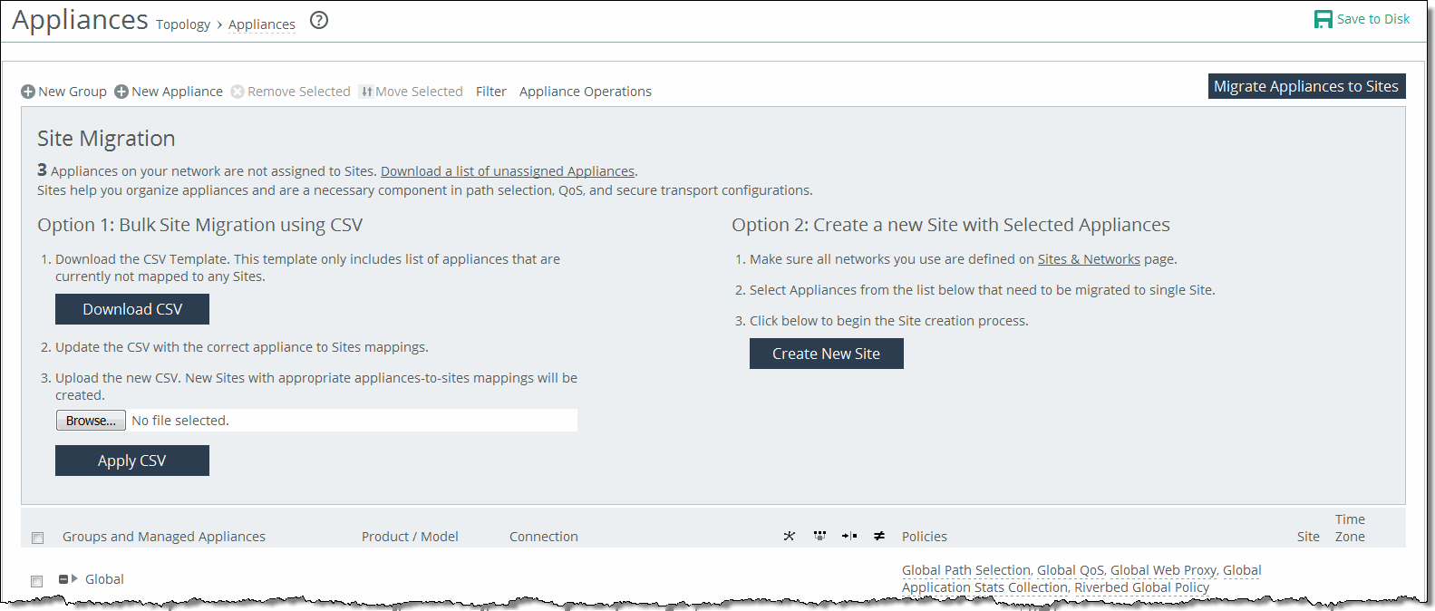
The SCC provides these migration tools:
• Bulk migration using a CSV template—Bulk migration allows you to migrate groups of appliances to more than one site in a single operation. The bulk migration wizard provides a custom CSV template. The SCC automatically populates the template with the appliances, group names, serial numbers, hostnames, and IP addresses currently managed by the SCC. For details, see
Migrating in bulk using the CSV template. • Create a new site from selected appliances—Alternatively you can create individual sites manually using the Create a New Site form in the Appliances page or the detailed New Sites form (for features such as secure transport) on the Sites & Networks page. Creating sites allows the user to map their unassigned appliances to sites. For details, see
Creating a new site from selected appliances. Migrating in bulk using the CSV template
You can migrate in bulk under Manage > Topology: Appliances.
1. In Appliances page, click Migrate Appliances to Sites to display the Site Migration page.
2. In the Site Migration page, click Download CSV to download the CSV template and open it in Excel.
3. Define the sites. The Site Name, Site Type, Site Region, Subnets, and Peers (if custom endpoints configured) are required. The Site Name column doesn’t accept commas. We recommend creating the region and type before you populate this CSV template. Uplink Gateway fields are ignored unless a connectivity template is specified. If one is specified, then Uplink Gateway is required. Internet traffic can be either Direct-to-Net or backhauled through a site. Specify a site to backhaul through or leave blank for Direct-to-Net.
4. Associate appliances to sites. The Object Type, Serial Number, and Site Name are required. The Site Name doesn’t accept commas. You can also assign the appliance to an already existing site.
5. Save, and then close the CSV file.
6. In the Site Migration page under Option 1, click Browse to navigate to the CSV template.
7. Click Apply CSV to upload the new CSV template to the SCC. New sites with appropriate appliances to sites mappings are created and displayed in the Appliance/Group table.
Creating a new site from selected appliances
You can create a new site in under Manage > Topology: Appliances.
1. Click Migrate Appliances to Sites to display the Site Migration panel.
2. Select the appliances you want to migrate.
3. Under Option 2, click Create New Site to expand the page and display the controls to create a site. Under Riverbed Appliances, the selected appliances automatically appear.
4. Enter a site name, site type, region, and a brief description that will help you identify the site.
About appliance groups
All groups are based on a nested hierarchy. You can add policies to groups. Global group policies are overridden by policies lower in the hierarchy.
You should carefully design your appliance hierarchy so that you can identify what policies are needed on the appliances in each group. Carefully designing the group hierarchy will ensure that you implement the best solution for your network.
Configuring appliance groups
You can configure appliances under Manage > Topology: Appliances. Click New Group to expand the page. These configuration options are available:
Name
Specifies the name for the group.
Parent Group
Specifies the parent group from the drop-down list. The default value is Global.
Comment
Provides a description to help you identify the group.
Add
Adds the group to the Appliance/Group table. The SCC redisplays the table and applies your changes to the running configuration, which is stored in memory.
Filtering the display of appliances
You can define filters to display only those appliances that need to be managed under Manage > Topology: Appliances. In the menu bar at the top of the page, click Filter to expand the page. Select the appliances that match the specified filter criteria. Type an expression into the fields to filter the display of appliances. The filter applies only to appliances, not groups. Click Apply Filter to select the appliances that match the criteria specified.
Managing appliance settings
Select the Appliances tab on the Appliance page to manage these appliance-specific settings:
• Configure appliance pages—You can configure or modify appliance feature settings, such as host settings, SSL settings, base interfaces, and so on. For details, see
Managing appliance pages. • Edit appliance properties—You can modify appliance properties, such as hostname, IP address, username and password. For details, see
Editing appliance properties. • Run appliance utilities—You can update the appliance serial number or reconnect to the appliance. For details, see
Running appliance utilities. • View inherited policies—You can view inherited policies by for an appliance and modify policies. For details, see
Running appliance utilities. • View policy drift—You can view drift between SCC policies and the actual configuration on a managed appliance. For details, see
Viewing policy drift. Displaying appliance tabs
You can display appliance tabs under Manage > Topology: Appliances. Select the name of the appliance you want to edit to expand the page and display the Appliance tabs.
Displaying appliance tabs
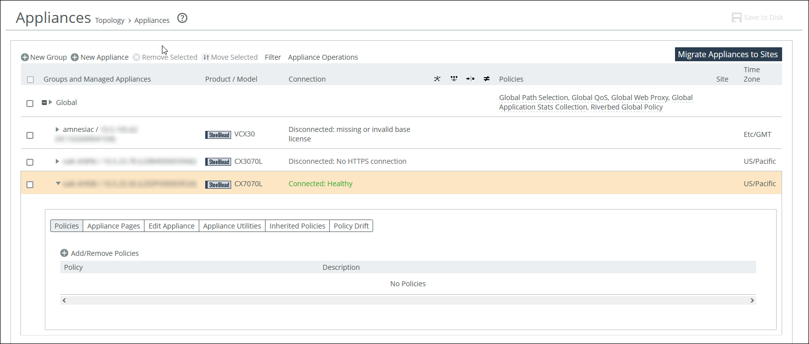
You can perform operations on policies, configuration settings, appliance properties, appliance utilities (that is, reconnect and serial number), inherited policies, and policy drift.
Adding a policy to an appliance
You can add a policy to an appliance under Manage > Topology: Appliances. Select the appliance name to expand the page and display the Appliance tabs. Click the + Add/Remove Policies to display the pop-up window, and select the policy you want to add. A message is displayed stating the policy has been added. To remove the policy, click Revert. Click Done to return to the appliances and group table.
Editing appliance properties
You can edit appliance properties under Manage > Topology: Appliances. Select the appliance name to expand the page, and then elect the Edit Appliance tab to display the appliance properties. These configuration options are available:
Serial Number
Displays the serial number for the appliance.
Hostname or IP Address
Specifies the hostname or IP address for the appliance.
Comment
Provides a comment to help you identify the appliance.
Group
Specifies a group from the drop-down list. The default group is Global.
Branch Managed
Prevents any remote action from being performed on the specified appliance. For example, you wouldn’t be able to push configurations to this appliance from the SCC.
Trusted
Untrusts an appliance. Only applicable to manually trusted appliances.
Auto Configure
(Use only when the policies have been configured.) Automatically pushes the current configuration (as defined by the policies for the appliance or appliance group) to the current remote appliance the next time it connects to the SCC. This feature is available only when the remote appliance is disconnected. This setting is automatically disabled after the push.
User Name
Specifies the username for the appliance.
Password/Confirm Password
Specifies and confirms the password for the appliance.
Running appliance utilities
You can run appliance utilities under Manage > Topology: Appliances. Select the name of the appliance you want to edit to display the Edit Appliance tab. Click Appliance Utilities to display the Editing Appliance Configuration <appliance>, Utilities panel. These configuration options are available:
Update
Updates the current appliance serial number. Sets the serial number for the appliance to the actual value stored on the appliance. The value is changed system-wide; the appliance remains accessible. The appliance must be connected to update the serial number.
Reconnect
Reconnects the SCC to the current appliance. You can establish a new connection to an appliance in about 30 seconds. Reconnecting doesn’t affect policy configurations.
Viewing policies inherited by an appliance
You can view inherited policies under Manage > Topology: Appliances. Select the name of the appliance you want to view to display the Edit Appliance tab. Select the Inherited Policies tab to display the policies for the appliance, and select the page to display the inherited policies. Select the policy to modify the policy. For details about policies, see
Managing path selection.Viewing policy drift
You can view policy drift under Manage > Topology: Appliances. Select an appliance, and then select the Policy Drift tab.
Policy Drift tab for an appliance
The page is divided into sections for SCC policy pages and appliance policy pages. Selecting an SCC policy page shows the configuration for that page in SCC. Selecting an appliance policy page redirects you to that configuration page in the Management Console for that appliance.
You can compare the two configurations to see where they are not synchronized. The SCC records any unsynchronized policy changes as policy drift. Additionally, changes made directly on a SteelHead appliance, even those that are reversed, are reported as policy drift here in the SCC’s Management Console. Previous versions of the SCC included limited information (an ≠ icon or simple notification) to indicate such changes. Now, the SCC reports policy drift changes page by page to aid in reviewing the specific settings.
Restarting the SCC clears all policy drift information.
Pushing policies to selected appliances or groups
You can push SCC configurations (in the form of policies) to selected appliances or appliance groups.
Any changes made to policies on the SCC don’t take effect on remote appliances until the new configurations are pushed to the appliances.
When you push SCC configurations (in the form of policies) to selected appliances or appliance groups, appliance page configurations are also pushed.
For details about appliance page configurations, see
Managing appliance pages. Any scheduled operations on appliance groups execute according to the time on the SCC, not the time on the remote appliance. For example, if the SCC clock is set to Pacific Daylight Time (PDT) but the remote appliance clock is set to Central European Summer Time (CEST), then an operation scheduled for midnight on the SCC (PDT) is executed at 9:00 AM on the remote appliance (CEST). This operation applies only to SteelHeads and Interceptors.
For detailed information about pushing global policies, see
Performing global policy pushes.You can abort a pending policy push using the SCC CLI command cmc policy abort job <job-id>.
You can push a configuration to an appliance or an appliance group under Manage > Topology: Appliances. Click Appliance Operations to display the Appliance Operations page. Select the appliances or appliance groups to which you want to push settings in the appliances table. Select Push Policies from the operation drop-down list. These configuration options are available:
Include Path Selection, QoS, and Applications (RiOS 9.0 and later); Web Proxy and Application Stats Collection (RiOS 9.1 and later)
Includes path selection rules, QoS profiles, applications, web proxy settings, and application statistics in the policy push. This option is not applicable to all appliance models. We recommend you do not select this when pushing policies.
Restart Optimization Service If Required
Automatically restarts the RiOS service on the appliances after the push.
Restart QoS Service If Required
Automatically restarts the QoS service, if required. We recommend you do not select this when pushing policies.
• For legacy outbound QoS (Advanced) policy changes—The QoS service must first be disabled if the policy push changes queue type of an existing QoS class. If the QoS service isn’t disabled the policy push fails.
• For legacy outbound QoS (Basic) and outbound QoS (Advanced)—Disables the QoS service on all appliances that you push to. This option temporarily disrupts QoS enforcement.
Restart Xbridge If Required automatically
Restarts Xbridge if required. This applies to Interceptor appliances only.
Schedule Deferred Push
Schedules the action for a later time and date. If this option isn’t selected, the action occurs the next time the appliance connects.
• Date and Time—Specify the date and time in this format: yyyy/mm/dd hh:mm:ss
This operation applies only to SteelHeads and Interceptors.
Push
Pushes your configuration changes to the selected appliances and groups.
You can abort a pending policy push using the SCC CLI command cmc policy abort job <job-id>.
Replacing (generating) peering certificates
You can replace the peering certificates used to secure the inner channel between the SteelHeads by generating new private keys and self-signed public certificates.
If possible, the certificates are signed by the certificate authority, otherwise they’re self-signed.
A policy push must be initiated to all SteelHeads for the new certificates to be used in peering. If the policy push excludes any affected SteelHeads, SSL optimization to the SteelHeads doesn’t work properly.
If CA is enabled, all newly generated certificates are automatically be signed. The existing certificates must be replaced to be signed.
You can replace (generate) peering certificates under Manage > Topology: Appliances. Click Appliance Operations to display the Appliance Operations page. Select Replace (Generate) Peering Certificates from the operation drop-down list. These configuration options are available under Self-Signed Certificate.
Common Name
Specifies the common name of a certificate.
• Appliance Hostname—Select if the common name is the hostname or IP address.
• Custom Name—Select to specify a common name other than the hostname or IP address.
To facilitate configuration, you can use wildcards in the name: for example, *.example.com. If you have three origin servers using different certificates, such as webmail.example.com, internal.example.com, and marketingweb.example.com, on the server-side SteelHeads, all three server configurations can use the same certificate name *.example.com.
Organization Name
Specifies the organization name (for example, the company).
Organization Unit Name
Specifies the organization unit name (for example, the section or department).
Locality
Specifies the city.
State
Specifies the state.
Country
Specifies the country (2-letter code only).
Email Address
Specifies the email address of the contact person.
Validity Period
Specifies how many days the certificate is valid.
Click Replace to replace the peering certificates.
Updating licenses
The SCC fetches and pushes licenses to selected appliances or groups. You can also fetch a license from the Riverbed License portal and store it locally. This option ignores the selected appliances and applies the license to all appliances specified in the license file.
CLMF license installation is not supported.
You can update licenses under Manage > Topology: Appliances. Click Appliance Operations to expand the page, and select License Update from the operation drop-down list. These configuration options are available under License Update Method:
Update License using Riverbed Licensing Portal
Updates the license using the Riverbed Licensing Portal.
From Local File
Specifies the path. Alternatively, click Browse to navigate to the local file directory.
Update
Updates the current license.
Starting and stopping appliances
You can start and stop the system service on selected appliances and appliance groups under Manage > Topology: Appliances. Click Appliance Operations to expand the page, and select Start/Stop Services from the operation drop-down list. These configuration options are available:
Service Action
Specifies Start, Stop, or Restart from the drop-down list.
Clean Data Store
Clears the RiOS data store. This option only applies to SteelHeads.
Schedule Deferred Service Action
Schedules the action for a later time and date. If this option isn’t selected, the action occurs the next time the appliance connects.
• Date and Time—Specify the date and time in this format: yyyy/mm/dd hh:mm:ss
This option only applies to SteelHeads and Interceptors.
The results of this operation can be viewed in the Operation History page.
Shutting down appliances
You can shut down the system on selected appliances and appliance groups under Manage > Topology: Appliances. You can also clean the data store and schedule a shutdown.
Click Appliance Operations to expand the page, and select Shutdown from the operation drop-down list. These configuration options are available:
Clean Data Store
Cleans the RiOS data store.
Schedule Deferred Shutdown
Schedules the action for a later time and date. If this option isn’t selected, the action occurs the next time the appliance connects.
• Date and Time—Specify the date and time in this format: yyyy/mm/dd hh:mm:ss
Shutdown
Shuts down the selected appliance and appliance groups. Click Shutdown.
The results of this operation can be viewed in the Operation History page.
Setting the password for appliances
You can set the password for administrator and monitor users on selected appliances and groups under Manage > Topology: Appliances.
The SCC sets the password used to connect with the remote appliance. The SCC automatically updates the password that’s used by the SCC to connect with the remote appliance.
Select the Appliance Operations tab to expand the page.
Select the Appliance Operations tab to expand the page. Select Set Password from the operation drop-down list. These configuration options are available:
User
Specifies admin or monitor in the text box.
Password
Specifies the password.
Confirm Password
Confirms the password.
Set Password
Sets the specified password.
The results of this operation can be viewed in the Operation History page.
Unlocking the secure vault
You can unlock the Secure Vault on selected appliances and appliance groups under Manage > Topology: Appliances. This operation applies only to SteelHeads.
The SCC unlocks the secure vault on the selected appliances or groups if the correct password has been specified. If successful, this operation also automatically updates the stored copy of the secure vault password for each selected appliance.
When the secure vault on an appliance or an appliance group is locked, you can’t push some configuration settings.
Click Appliance Operations to display the Appliance Operations page. Select Unlock Secure Vault from the operation drop-down list. Specify the password and click Unlock Vault to unlock the secure vault on the selected appliances or appliance groups.
The results of this operation can be viewed in the Operation History page.
Changing the secure vault password
You can change the password for the Secure Vault on selected appliances and appliance groups under Manage > Topology: Appliances. This operation applies only to SteelHeads and SteelHead Mobiles.
The SCC must know the current secure vault password that’s set on the SSL configuration page of each appliance. This operation automatically updates the stored copy of each password on the selected appliance.
1. Click Appliance Operations to display the Appliance Operations page.
2. Select Change Secure Vault Password from the operation drop-down list.
3. Specify the current password, or leave the text box blank if the factory default password is used.
4. Specify the new vault password, or leave the text box blank to reset to the factory default password, and confirm the new secure vault password.
5. Click Change Password to change the secure vault password.
The results of this operation can be viewed in the Operation History page.
Sending CLI commands
You can send a set of CLI commands to the selected appliances and groups under Manage > Topology: Appliances. Click Appliance Operations to display the Appliance Operations page. Select Send CLI Commands from the operation drop-down list. These configuration options are available:
Text field
Specifies the set of CLI commands. Paste or type the set of CLI commands. Each command must be on a separate line. This feature provides the flexibility to configure your appliances using CLI commands. For example, using the CLI commands in policies:
• enables you to configure new appliance features.
• enables you to override specific configuration items at a subpage granularity without maintaining multiple copies of otherwise identical policies.
Sending CLI commands has these restrictions:
• The SCC can’t parse the CLI commands and perform a check to verify if they’re compatible with the rest of the configuration; therefore, a failure is harder to diagnose.
• The CLI commands from all assigned policies are sent with every push. Given this, you must check each policy that’s assigned to each parent group and individually check its details to review exactly what was pushed.
Schedule Deferred Command Execution
Schedules the action for a later time and date. If this option isn’t selected, the action occurs the next time the appliance connects.
• Date and Time—Specify the date and time in this format: yyyy/mm/dd hh:mm:ss
Send
Executes the commands on the appliance.
Starting or stopping SteelCentral NetShark service
You can start or stop the SteelCentral NetShark service under Manage > Topology: Appliances. This operation applies only to SteelHeads and can take up to five minutes to take effect.
Click Appliance Operations to display the Appliance Operations page. Select SteelCentral NetShark from the operation drop-down list. These configuration options are available:
Service Action
Specifies Start or Stop from the drop-down list.
Apply
Applies your settings to the running configuration.
Disabling SSL server certificate export
You can disable the SSL server certificate export feature under Manage > Topology: Appliances. For security reasons, once a certificate export has been disabled, it can’t be reenabled.
This operation applies only to SteelHeads.
Consider making SSL server certificates and private keys nonexportable with your particular security goals in mind. Before doing so, you must have a thorough understanding of its impact. Use caution and consider these best practices before making SSL configurations nonexportable:
• After disabling export on a new SteelHead running 7.0.1, you can’t reenable it unless you clear the secure vault and perform a factory reset on the SteelHead. (Performing a factory reset results in losing your configuration settings.)
• After upgrading a SteelHead to 7.0.1 and disabling export, you can’t export any preexisting or newly added server certificates and private keys to another SteelHead.
• After disabling export, any newly added server certificates and keys are marked as nonexportable.
• After disabling export and then downgrading a SteelHead to a previous RiOS version, you can’t export any of the existing server certificates and private keys. You can export any newly added server certificates and private keys.
• Disabling export prevents you from copying the secure vault content.
Click Appliance Operations to display the Appliance Operations page. Select Disable SSL Server Certificate Export from the operation drop-down list. Click Disable Export.
Joining or leaving a windows domain
You can join or leave a Windows domain under Manage > Topology: Appliances. This action can take up to five minutes to take effect.
For detailed information about Windows domains, see the SteelHead User Guide.
Click Appliance Operations to display the Appliance Operations page. Select Join/Rejoin/Leave a Windows Domain from the operation drop-down list. These configuration options are available:
Domain action
Joins, rejoins, or leaves the domain. If you’re in domain mode and have joined a domain, you can’t change to local work-group mode until you leave the domain.
Active Directory Domain Name/Realm
Specifies the domain in which to make the SteelHead a member. Typically, this is your company domain name. RiOS supports Windows 2000 or later domains. RiOS doesn’t support nondomain accounts other than administrator accounts. If you create Local mode shares on a nonadministrator account, your security permissions for the share aren’t preserved on the origin-file server.
Domain Login
Specifies the login name, which must have domain join privileges. Domain administrator credentials aren’t strictly required, except when you join the domain as an Active Directory integration. RiOS deletes domain administrator credentials after the join.
Password
Specifies the password. This control is case sensitive.
Domain Controller Name(s)
Specifies the hosts that provide user login service in the domain, separated by commas. If the Join Account Type is Active Directory Integrated 2008 or later and the Windows domain controllers are a combination of Windows 2003, 2008, and later, then a name list of Windows 2008 or later domain controllers is required. We recommend specifying the domain controller names in environments where there is varying latency between the SteelHead and the domain controllers.
Short Domain Name
Specifies the short domain (NetBIOS) name if it doesn’t match the first portion of the Active Directory domain name. The short domain name is case sensitive.
Apply
Applies your changes to the running configuration.
Fetching appliance-specific configurations
You can copy (that is, fetch) appliance-specific configuration settings under Manage > Topology: Appliances. The remote appliance must be connected to the SCC.
Select the name of the appliance you want to copy to expand the page and display the Appliance tabs. Select the Appliances Pages tab to expand the page, and scroll to the bottom of the page. Select the check box. By default, none of the fetched pages are included. Click Fetch Appliance Config to display the configuration pages in the pages table.
Performing global policy pushes
You can perform global policy pushes for path selection, QoS, web proxy, application Statistics collection, and the Riverbed Global Policy under Manage > Topology: Appliances.
When you perform a policy push, the SCC is the primary configuration; any local changes made on SteelHeads are overwritten.
In SCC 9.0 or later when the SCC creates custom applications using port or host labels, the SCC assumes that the port and host labels are created at the Global policy level (that is, under the Global group). When you perform a policy push to the SteelHead, if the appliance pages include port or host labels, then the policy push might fail. If you’re running RiOS 9.0 or later, we recommend you create any appliance level host and port labels in the Global policy, delete the appliance level pages to include these, and use global policies going forward. For non-RiOS 9.0 or later appliances, we recommend you use Global level host and port labels.
For detailed information about pushing policies to selected appliances or appliance groups, see
Pushing policies to selected appliances or groups.To the right of Global, click the feature link to display the global policy push controls for the feature. Under Policy Push Control on the right side of the page, click Include in Push to expand the page and display the Push to Appliances panel.
To exclude appliances from the push, under Push Control on the right side of the page, click Exclude from Push. (This option only appears if you have clicked Include in Push.)
These configuration options are available:
Push to Appliances
Pushes your path selection rules:
• Site Types—Click the text box to display site types to choose from. Select the site types one at a time to add them to the text box. After you select the site type, it is displayed in the text box. To remove a site type, click the X. To view what sites make up the site type, click See More. We recommend that you choose site types rather than sites to organize your rules as site types make the management of rules easier.
• Sites—Click the text box to display sites to choose from. Select the sites one at a time to add them to the text box. After you select the site, it is displayed in the text box. To remove a site, click the X. To view site details, click See Details.
Push All
Pushes all related configurations, such as applications, QoS, and path selection rules.
Push Only Path Selection Configuration
Pushes only path selection configuration settings to remote appliances.
Push
Pushes configuration settings to the selected sites or site types. Click Clear to clear your settings.
You can view the status of your pushes. In the Push Status panel click More to be directed to the Operations table that lists the status of current pushes.
To push settings for the Riverbed global policy, to the right of Global, click Riverbed Global Policy to display the Editing Policy Riverbed Global Policy page.
Pushing Riverbed global policy settings
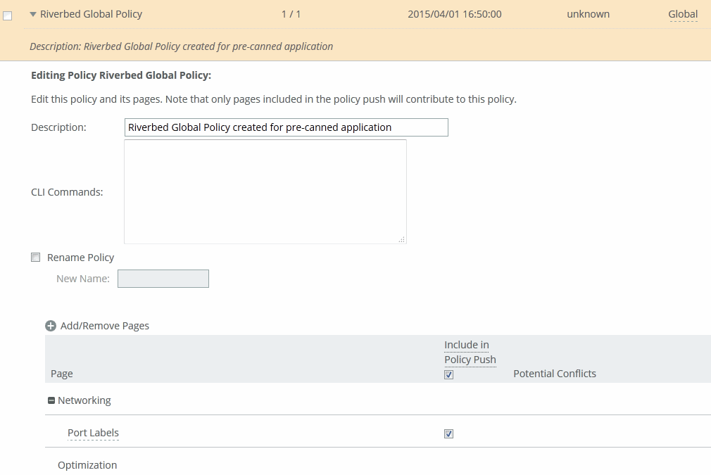
Select Include in Policy Push for the policy pages that you want to include in the Riverbed Global Policy and click Apply.
To view push status, choose Manage > Operations > Operation History and view the Operations table. The status of current pushes are listed.
Trusting appliances using security keys
You can enable the SCC to trust detected appliances based on an appliance-specific security keys under Manage > Topology: Appliances. Strict key verification prevents the SCC from inadvertently connecting with rogue appliances. If you select this option, the SCC doesn’t connect with appliances whose correct SSH public keys are not known by the SCC.
The SCC requires you to enter the SteelHead SSH public key before allowing communication.
You must enable strict key verification and configure security keys for the appliance before you can trust appliances using a security key.
For details about creating security keys on appliances, see
Managing SSL settings.You can trust appliances by key verification under Administration > Security: SCC Security. Scroll to the bottom of the page, select Strict Key Verification, and click Apply.
Retrieve the SSH public key of a SteelHead with the show ssh server publickey command:
Copy the security key, and then choose Manage > Topology: Appliances. Scroll to the bottom of the page, and click Trust Appliances by Key to expand the page. Paste the security keys in the text box and click Trust.
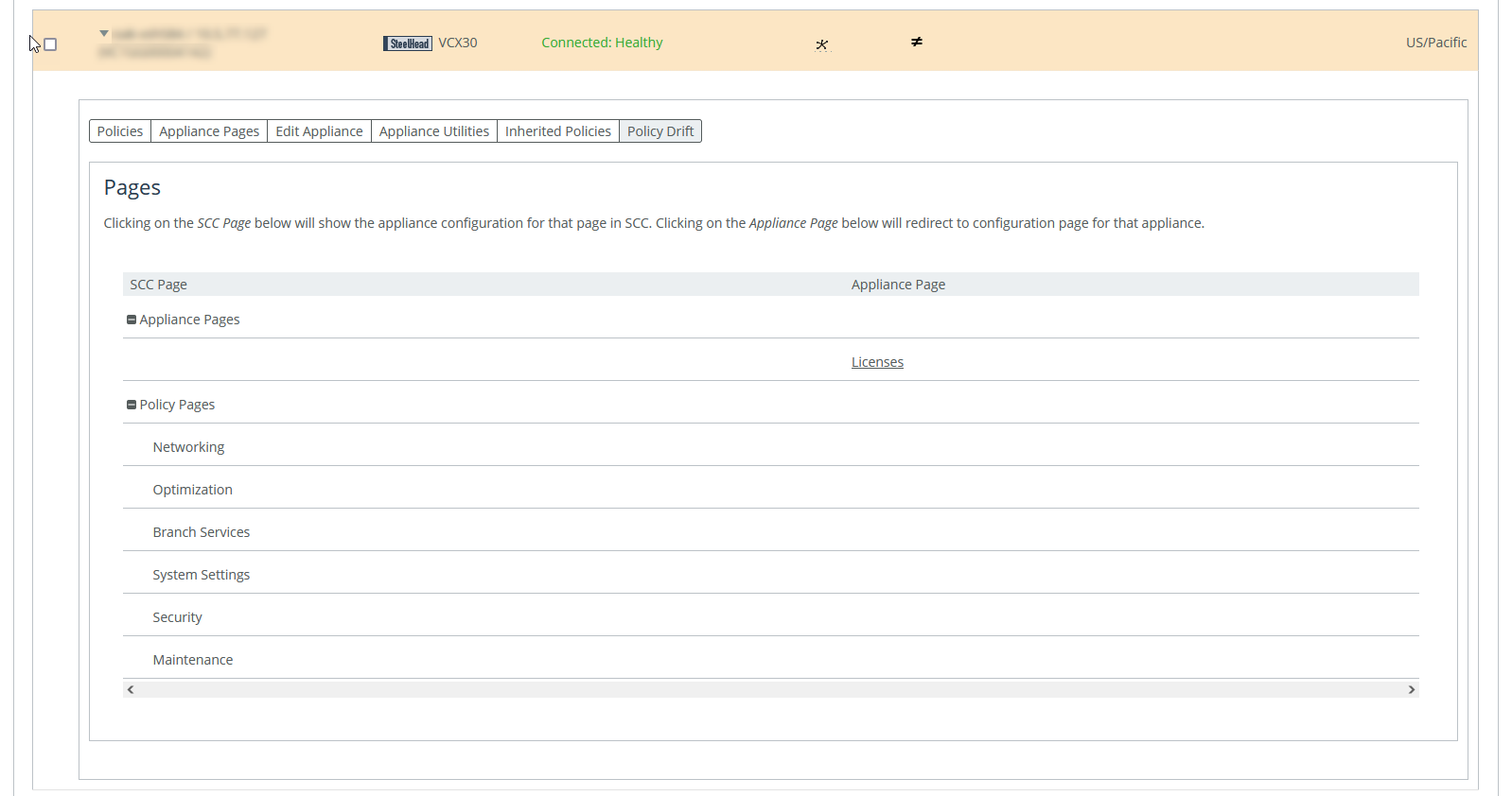
Managing appliance pages
You configure appliance configuration settings in the Appliances page: Appliance Pages tab. Appliance configuration settings are organized into appliance configuration pages so that you can easily configure common features, such as host settings and in-path rules.
Each appliance configuration page lists the applicable appliances and supported software on the right side of the page. You must pay close attention to the supported software versions—if the feature isn’t supported by the software you’re running your configuration changes can’t be pushed to the appliance.
Changes made to the appliance configuration pages aren’t applied until you have pushed the configuration to the appliance.
Select the name of the appliance you want to configure to expand the page and display the available configuration tabs, and then select Appliance Pages. Select the name of the feature, such as Host Settings.
Editing Appliance
Specifies the appliance you want to edit from the drop-down list.
Page
Specifies the feature you want to configure from the drop-down list.
Include/Exclude
Includes or excludes this page in the policy push.
Page Applicable to
Lists applicable appliances and software restrictions on the right side of the page. Make sure you have the correct product and software version installed—if you have a version mismatch you can’t push configuration changes to your appliances.
Changes are made on the remote appliance after a policy push. When you perform a policy push, the SCC is the primary configuration; any local changes made on managed appliances are overwritten.
These sections describe each feature you can configure or modify in detail.
Managing host settings
You can edit host settings under Editing Appliance Configuration: <hostname>, Host Settings.
This page applies to SteelHead and Interceptor.
Choose Manage > Topology: Appliances, and then select the name of the appliance you want to edit to expand the page and display the Appliance tabs. Select the Appliance Pages tab to display the Appliance Configuration Pages list. Under Appliance Configuration Pages, click Host Settings to display the Editing Appliance Configuration: <hostname>, Host Settings page.
Click Include or Exclude to include or exclude this configuration from the policy push for the specified appliance. Your changes aren’t applied to the specified appliance until the policy is pushed to the appliance.
These configuration options are available:
Hostname
Specifies the hostname of the appliance.
Apply
Applies your settings to the running configuration.
Managing base interfaces
You can configure base interface settings in the Appliance Configuration: <hostname>, Base Interfaces page. This page applies to SteelHead and Interceptor.
When you initially ran the configuration wizard, you set required settings for the base interfaces for the SteelHeads. Only use the controls on this page if you require modifications or additional configuration:
• Primary Interface—On the appliance, the primary interface is the port you connect to the LAN switch. The primary interface is the appliance management interface. You connect to the primary interface to use the Management Console or the CLI.
• Auxiliary Interface—On the appliance, the auxiliary interface is an optional port you can use to connect the appliance to a non-Riverbed network management device. The IP address for the auxiliary interface must be on a subnet different from the primary interface subnet.
• Main Routing Table—Displays a summary of the main routing table for the appliance. If necessary, you can add static routes that might be required for out-of-path deployments or particular device management subnets.
Configure base interface settings
You can configure base interface settings under Manage > Topology: Appliances. Select the name of the appliance you want to edit to expand the page and display the Appliance tabs, and then select the Appliance Pages tab to display the Appliance Configuration Pages list. Under Appliance Configuration Pages, click Base Interfaces to display the Editing Appliance Configuration: <hostname>, Base Interfaces page.
Click Include or Exclude to include or exclude this configuration from the policy push for the specified appliance. Your changes aren’t applied to the specified appliance until the policy is pushed to the appliance.
These configuration options are available under Primary Interface:
Enable Primary Interface
Enables the appliance management interface, which can be used for both managing the SteelHead and serving data for a server-side out-of-path (OOP) configuration.
Obtain IPv4 Address Automatically
Automatically obtains the IP address from a DHCP server. A DHCP server must be available so that the system can request the IP address from it. The primary and in-path interfaces can share the same network subnet. The primary and auxiliary interfaces can’t share the same network subnet.
Enable IPv4 Dynamic DNS
Sends the hostname with the DHCP request for registration with Dynamic DNS. The hostname is specified in the Networking > Networking: Host Settings page.
Specify IPv4 Address Manually
Indicates that you don’t use a DHCP server to set the IPv4 address. Specify these settings:
• IPv4 Address—Specify an IP address.
• IPv4 Subnet Mask—Specify a subnet mask.
• Default IPv4 Gateway—Specify the default gateway IPv4 address. The default gateway must be in the same network as the primary interface. You must set the default gateway for in-path configurations.
Do Not Assign An IPv4 Address
Enables the interface without assigning an IP address.
Specify IPv6 Address Manually
Allows you to manually specify these settings to set an IPv6 address.
• IPv6 Address—Specify an IP address using this format: eight 16-bit hexadecimal strings separated by colons, 128-bits. For example: 2001:38dc:0052:0000:0000:e9a4:00c5:6282
You don’t need to include leading zeros. For example: 2001:38dc:52:0:0:e9a4:c5:6282
You can replace consecutive zero strings with double colons (::). For example: 2001:38dc:52::e9a4:c5:6282
• IPv6 Prefix—Specify a prefix. The prefix length is 0 to 128, separated from the address by a forward slash (/). In this example, 60 is the prefix: 2001:38dc:52::e9a4:c5:6282/60
• IPv6 Gateway—Specify the gateway IP address. The gateway must be in the same network as the primary interface. You can’t set an IPv6 address dynamically using a DHCP server.
Speed
Specifies a speed from the drop-down list. The default value is Auto.
Duplex
Specifies Auto, Full, or Half from the drop-down list. The default value is Auto.
If your network routers or switches don’t automatically negotiate the speed and duplex, be sure to set them manually.
The speed and duplex must match (LAN and WAN) in an in-path configuration. If they don’t match, you might have a large number of errors on the interface when it is in bypass mode, because the switch and the router aren’t set with the same duplex settings.
MTU
Specifies the MTU value. The MTU is the largest physical packet size, measured in bytes, that a network can send. The default value is 1500.
These configuration options are available under Auxiliary Interface:
Enable Aux Interface
Enables an auxiliary interface, which can be used only for managing the SteelHead. It can’t be used for an out-of-path (OOP) SteelHead data service. Typically, this is used for device-management networks.
Obtain IPv4 Address Automatically
Automatically obtains the IP address from a DHCP server. A DHCP server must be available so that the system can request the IP address from it. The primary and in-path interfaces can share the same subnet. The primary and auxiliary interfaces can’t share the same network subnet.
Enable IPv4 Dynamic DNS
Sends the hostname with the DHCP request for registration with Dynamic DNS. The hostname is specified in the Networking > Networking: Host Settings page.
Specify IPv4 Address Manually
Indicates that you don’t use a DHCP server to set the IPv4 address. Specify these settings:
• IPv4 Address—Specify an IP address.
• IPv4 Subnet Mask—Specify a subnet mask.
Do Not Assign An IPv4 Address
Enables the interface without assigning an IP address.
Specify IPv6 Address Manually
Sets an IPv6 address. Specify these options:
• IPv6 Address—Specify an IP address, using this format: eight 16-bit hexadecimal strings separated by colons, 128-bits. For example: 2001:38dc:0052:0000:0000:e9a4:00c5:6282
You don’t need to include leading zeros. For example: 2001:38dc:52:0:0:e9a4:c5:6282
You can replace consecutive zero strings with double colons (::). For example: 2001:38dc:52::e9a4:c5:6282
• IPv6 Prefix—Specify a prefix. The prefix length is 0 to 128, separated from the address by a forward slash (/). In this example, 60 is the prefix: 2001:38dc:52::e9a4:c5:6282/60
You can’t set an IPv6 address dynamically using a DHCP server.
Speed
Specifies the speed from the drop-down list. The default value is Auto.
Duplex
Specifies Auto, Full, or Half from the drop-down list. The default value is Auto.
If your network routers or switches don’t automatically negotiate the speed and duplex, be sure to set them on the device manually.
The speed and duplex must match (LAN and WAN) in an in-path configuration. To avoid a speed and duplex mismatch, configure your LAN external pair to match the WAN external pair.
MTU
Specifies the MTU value. The MTU is the largest physical packet size, measured in bytes, that a network can send. The default value is 1500.
Under the Main IPv4 Routing table, you can configure a static routing in the main routing table for out-of-path deployments or if your device management network requires static routes.
Configuring the main IPv4 routing table
Under the Main IPv4 Routing Table, click + Add a New Route to expand the page. These configuration options are available:
Add a New Route
Displays the controls to add a route.
Destination IPv4 Address
Specifies the destination IP address.
Gateway IPv4 Address
Specifies the IP address for the gateway. The gateway must be in the same network as the in-path interface.
Interface
Specifies the interface for the IPv4 route from the drop-down list.
Add
Adds the route to the table list.
You can configure a static routing in the main routing table for out-of-path deployments or if your device management network requires static routes.
Configuring the main IPv6 routing table
Under the Main IPv6 Routing Table, click + Add a New Route to expand the page. These configuration options are available:
Add a New Route
Displays the controls for adding a new route.
Destination IPv6 Address
Specifies the destination IP address.
IPv6 Prefix
Specifies a prefix. The prefix length is from 0 to 128 bits, separated from the address by a forward slash (/).
Gateway IPv6 Address
Specifies the IP address for the gateway. The gateway must be in the same network as the primary or auxiliary interface you’re configuring.
Interface
Specifies an interface for the IPv6 route from the drop-down list.
Add
Adds the route to the table list.
Managing in-path interface settings
You can edit in-path interface settings in the Editing Appliance Configuration: <hostname>, In-Path Interfaces page.
You configure in-path interfaces for deployments where the SCC is in the direct path (the same subnet) as the client and the server in your network. You also set the in-path gateway (WAN router).
In the Riverbed system, appliances have a unique in-path interface for each pair of LAN/WAN ports. For each appliance, the SCC detects LAN/WAN pairs, including those added through bypass cards, and identifies them according to slot (for example, inpath0_0, inpath0_1, inpath1_0, inpath1_1, and so on).
In the In-Path Interfaces page, you can clear either the IPv4 Address field or the IPv6 Address field, but not both. You must use the CLI to clear both addresses. Use the no interface <interface-name> ip address and the no interface <interface-name> ipv6 address <ipv6-address> to clear both. For details, see the Riverbed Command-Line Interface Reference Guide.
For management interfaces, use the main routing table. For detailed information about the main routing table, see
Managing base interfaces.This page applies to SteelHead and Interceptor.
Configuring in-path interfaces
You can configure in-path interfaces under Manage > Topology: Appliances. Select the name of the appliance you want to edit to expand the page and display the Appliance tabs, and select the Appliance Pages tab to display the Appliance Configuration Pages list.
Under Appliance Configuration Pages, click In-Path Interfaces to display the Editing Appliance Configuration: <hostname>, In-Path Interfaces page.
This configuration option is available under In-Path Settings to enable link state propagation:
Enable Link State Propagation
Shortens the recovery time of a link failure in physical in-path deployments. Link state propagation (LSP) communicates link status between the devices connected to the SteelHead. When you enable this LSP, RiOS monitors the link state of each SteelHead LAN-WAN pair.
If either physical port loses link status, the corresponding interface disconnects, blocking the link. This control allows a link failure to quickly propagate through a chain of devices. If the link recovers, the SteelHead restores the corresponding interface automatically.
LSP is enabled by default.
You can’t reach a MIP interface when LSP is also enabled and the corresponding in-path interface fails.
• Cloud Accelerator and SteelHead Cloud models don’t support LSP.
• SteelHead appliances running RiOS 8.0.3 or later with ESXi 6.5 using a Riverbed NIC card support LSP.
These SteelHead appliance configurations don’t support LSP:
• SteelHead models running ESX/ESXi 4.0 or 4.1
• SteelHead models running RiOS 8.0.2 or earlier
Select the interface that you want to edit to expand the page.
Configuring in-path interfaces
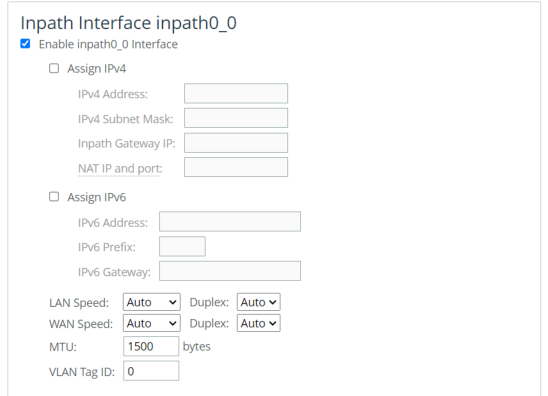
To edit the interface, select the enable interface check box. These configuration options are available:
Assign IPv4
Specifies to use IPv4.
IPv4 Address
Specifies an IP address. This IP address is the in-path main interface.
In the In-Path Interfaces page, you can clear either the IPv4 Address field or the IPv6 Address field, but not both. You must use the CLI to clear both addresses. Use the no interface <interface-name> ip address command and the no interface <interface-name> ipv6 address <ipv6-address> command to clear both. For details, see the Riverbed Command-Line Interface Reference Guide.
IPv4 Subnet Mask
Specifies the subnet mask.
In-Path Gateway IP
Specifies the IP address for the in-path gateway. If you have a router (or a Layer-3 switch) on the LAN side of your network, specify this device as the in-path gateway.
If there is a routed network on the LAN-side of the in-path appliance, the router that’s the default gateway for the appliance must not have the ACL configured to drop packets from the remote hosts as its source. The in-path appliance uses IP masquerading to appear as the remote server.
Assign IPv6
Assigns an IPv6 address. IPv6 addresses are disabled by default. You can only assign one IPv6 address per in-path interface.
The primary and in-path interfaces can share the same subnet. The primary and auxiliary interfaces can’t share the same network subnet.
IPv6 Address
Specifies a global or site-local IPv6 address. This IP address is the in-path main interface. You can’t use a DHCP server to assign an IPv6 address automatically.
In the In-Path Interfaces page, you can clear either the IPv4 Address field or the IPv6 Address field, but not both. You must use the CLI to clear both addresses. Use the no interface <interface-name> ip address and the no interface <interface-name> ipv6 address <ipv6-address> to clear both. For details, see the Riverbed Command-Line Interface Reference Guide.
IPv6 Prefix
Specifies the prefix. The prefix length is 0 to 128 bits, separated from the address by a forward slash (/). In this example, 60 is the prefix: 2001:38dc:52::e9a4:c5:6282/60
IPv6 Gateway
Specifies the IPv6 address for the in-path gateway. You can use a link local address. If you have a router (or a Layer-3 switch) on the LAN side of your network, specify this device as the in-path gateway.
If there is a routed network on the LAN-side of the in-path appliance, the router that’s the default gateway for the appliance must not have the ACL configured to drop packets from the remote hosts as its source. The in-path appliance uses IP masquerading to appear as the remote server.
LAN Speed and Duplex and WAN Speed and Duplex
• Speed—Select Auto, 1000, 100, or 10 from the drop-down list. The default value is Auto.
• Duplex—Select Auto, Full, or Half from the drop-down list. The default value is Auto.
If your network routers or switches don’t automatically negotiate the speed and duplex, be sure to set them on the device manually.
The speed and duplex must match (LAN and WAN) in an in-path configuration. To avoid a speed and duplex mismatch, configure your LAN external pair to match the WAN external pair.
Speed and duplex mismatches can easily occur in a network. For example, if one end of the link is set at half duplex or full duplex and the other end of the link is configured to autonegotiate (auto), the link defaults to half duplex, regardless of the duplex setting on the nonautonegotiated end. This duplex mismatch passes traffic, but it causes interface errors and results in degraded optimization.
These guidelines can help you avoid speed and duplex mismatches when configuring the SteelHead:
• Routers are often configured with fixed speed and duplex settings. Check your router configuration and set it to match the SteelHead WAN and LAN settings. Make sure that your switch has the correct setting.
• After you finish configuring the SteelHead, check for speed and duplex error messages (cyclic redundancy check (CRC) or frame errors) in the System Log page of the Management Console.
• If there is a serious problem with the SteelHead and it goes into bypass mode (that’s, it automatically continues to pass traffic through your network), a speed and duplex mismatch might occur when you reboot the SteelHead. To avoid a speed and duplex mismatch, configure your LAN external pair to match the WAN external pair.
MTU
Specifies the MTU value. The MTU is the largest physical packet size, measured in bytes, that a network can send. Applies to optimized traffic only. The default value is 1500.
VLAN Tag ID
Specifies the VLAN tag that the appliance uses to communicate with other SteelHeads in your network. The VLAN Tag ID might be the same value or a different value than the VLAN tag used on the client. A zero (0) value specifies nontagged (or native VLAN) and is the correct setting if there are no VLANs present. As an example, if the in-path interface is 192.168.1.1 in VLAN 200, you would specify tag 200.
When the SteelHead communicates with a client or a server, it uses the same VLAN tag as the client or the server. If the SteelHead can’t determine which VLAN the client or server is in, it doesn’t use the VLAN tag (assuming that there is no router between the SteelHead and the client or server).
You must also define in-path rules to apply to your VLANs.
These configuration options are available under Management Interface <hostname>:
Enable Appliance Management on This Interface
Enables a secondary MIP interface that you can reach through the physical in-path LAN and WAN interfaces. Configuring a secondary MIP interface allows management of SteelHeads from a private network while maintaining a logical separation of network traffic. If LSP or fail-to-block is enabled, a message reminds you to disable the feature before enabling the MIP interface.
IPv4 Address
Specifies the IP address for the MIP interface.
IPv4 Subnet Mask
Specifies the subnet mask.
Specify IPv6 Address
Enables IPv6 support on this interface.
IPv6 Address
Specifies the IPv6 address.
IPv6 Prefix
Specifies the prefix. The prefix length is 0 to 128 bits, separated from the address by a forward slash (/). In this example, 60 is the prefix: 2001:38dc:52::e9a4:c5:6282/60
VLAN Tag ID
Specifies a numeric VLAN Tag ID. When you specify the VLAN Tag ID for the MIP interface, all packets originating from the SteelHead from the MIP interface are tagged with that identification number. The VLAN Tag ID might be the same value or a different value than the in-path interface VLAN tag ID. The MIP interface could be untagged and the in-path interface could be tagged and vice versa. A zero (0) value specifies nontagged (or native VLAN) and is the correct setting if there are no VLANs present. For example, if the MIP interface is 192.168.1.1 in VLAN 200, you would specify tag 200.
Managing subnet side rules
You configure subnet side rules in the Editing Appliance Configuration: <hostname>, Subnet Side Rules page.
You need to configure subnet side rules to support Flow Export on a virtual in-path deployment.
Subnet side rules enable you to configure subnets as LAN-side subnets or WAN-side subnets for a virtual in-path SteelHead appliance. The subnet side rules determine whether traffic originated from the LAN or the WAN-side of the SteelHead appliance based on the source subnet. You must configure subnets on each SteelHead appliance in a virtual in-path configuration, as the subnets for each will likely be unique.
With subnet side rules in place, a virtual in-path SteelHead can use flow export collectors such as NetFlow to analyze nonoptimized or passed through traffic correctly. Otherwise, the SteelHead appliance can’t discern whether the traffic is traveling from the LAN to the WAN or in the opposite direction. This can result in over-reporting traffic in a particular direction or for a particular interface.
FakeIndex is necessary for correct optimized traffic reporting. For details, see the SteelHead Deployment Guide.
You can’t delete the default rule, Default, which optimizes all remaining WAN-side traffic that hasn’t been selected by another rule. This rule is always listed last.
This page applies to SteelHead.
Configuring subnet side rules settings
You can configure subnet side rules settings under Manage > Topology: Appliances. Select the name of the appliance you want to edit to expand the page and display the Appliance tabs, and select the Appliance Pages tab to display the Appliance Configuration Pages list.
Under Appliance Configuration Pages, click Subnet Side Rules to display the Editing Appliance Configuration: <hostname>, Subnet Side Rules page. These configuration options are available:
Add a Subnet Side Rule
Displays the controls to create a subnet side rule.
Insert Rule At
Specifies Start, End, or a rule number from the drop-down list. SteelHead appliances evaluate rules in numerical order starting with rule 1. If the conditions set in the rule match, then the rule is applied, and the system moves on to the next packet. If the conditions set in the rule don’t match, the system consults the next rule. For example, if the conditions of rule 1 don’t match, rule 2 is consulted. If rule 2 matches the conditions, it is applied, and no further rules are consulted.
Subnet
Specifies the subnet. Use this format: <ip-address>/<subnet-mask>
In SCC 9.8, this field also accepts IPv6 addresses.
• IPv6 Address—Specify an IP address using this format: eight 16-bit hexadecimal strings separated by colons, 128-bits. For example: 2001:38dc:0052:0000:0000:e9a4:00c5:6282
You don’t need to include leading zeros. For example: 2001:38dc:52:0:0:e9a4:c5:6282
You can replace consecutive zero strings with double colons (::). For example: 2001:38dc:52::e9a4:c5:6282
• IPv6 Prefix—Specify a prefix. The prefix length is 0 to 128, separated from the address by a forward slash (/). In this example, 60 is the prefix: 2001:38dc:52::e9a4:c5:6282/60
Subnet is on the LAN side of this appliance
Specifies that the subnet is on the LAN side of the device. In virtual in-path configurations, all traffic is flowing in and out of one physical interface.
Subnet is on the WAN side of this appliance
Specifies that the subnet is on the WAN side of the device. In virtual in-path configurations, all traffic is flowing in and out of one physical interface.
Add
Adds the rule to the subnet map table. The Management Console redisplays the subnet map table and applies your changes to the running configuration, which is stored in memory.
Managing SSL settings
You configure SSL settings for a specific appliance in the Editing Appliance Configuration: <hostname>, SSL page.
SSL is a cryptographic protocol that provides secure communications between two parties over the internet. Typically, in a web-based application, it is the client that authenticates the server. To identify itself, an SSL certificate is installed on a web server and the client checks the credentials of the certificate to make sure it is valid and signed by a trusted third party. Trusted third parties that sign SSL certificates are called certificate authorities (CA).
This page applies to SteelHead.
For detailed information, see the SteelHead User Guide.
Displaying SSL tabs
You can display SSL tabs under Manage > Topology: Appliances. Select the name of the appliance you want to edit to expand the page and display the Appliance tabs, and then select the Appliance Pages tab to display the Appliance Configuration Pages list.
Under Appliance Configuration Pages, click SSL to display the Editing Appliance Configuration: <hostname>, SSL page. To display certificates PEM, replace certificates, or generate CSR, select the Appliance Pages tab to expand the page and display configuration setting.
Displaying the certificate PEM
You can display the certificate PEM for the selected appliance in the Editing Appliance Configuration: <hostname>, SSL page.
Choose Manage > Topology: Appliances to display the Appliances page. Select the name of the appliance you want to edit to expand the page and display the Appliance tabs, and then select the Appliance Pages tab to display the Appliance Configuration Pages list.
Under Appliance Configuration Pages, click SSL to display the Editing Appliance Configuration: <hostname>, SSL page. Select the Display Certificate PEM tab to display the certificate in PEM format.
Replacing the SSL certificate
You can replace SSL certificates for the selected appliance in the Editing Appliance Configuration: <hostname>, SSL page.
Choose Manage > Topology: Appliances to display the Appliances page. Select the name of the appliance you want to edit to expand the page and display the Appliance tabs, and then select the Appliance Pages tab to display the Appliance Configuration Pages list.
Under Appliance Configuration Pages, click SSL to display the Editing Appliance Configuration: <hostname>, SSL page. Select the Replace Certificate tab to expand the page.
Replacing a certificate
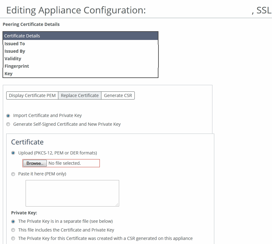
These configuration options are available:
Import Certificate and Private Key
Imports the certificate and key. The page displays controls for browsing to and uploading the certificate and key files. You can also use the text box to copy and paste a PEM file. The private key is required regardless of whether you’re adding or updating the certificate.
Certificate
• Upload—Browse to the local file in PKCS-12, PEM, or DER formats.
• Paste it here (PEM)—Copy and then paste the contents of a PEM file.
Private Key
Specifies the private key origin. The Private Key is in a separate file (see below)—You can either upload it or copy and paste it. This file includes the Certificate and Private Key. The Private Key for this Certificate was created with a CSR generated on this appliance.
Separate Private Key
• Upload (PEM or DER formats)—Browse to the local file in PEM or DER formats.
• Paste it here (PEM only)—Paste the contents of a PEM file.
• Decryption Password—Specify the decryption password, if necessary. Passwords are required for PKCS-12 files, optional for PEM files, and never needed for DER files.
Import Certificate and Key
Imports the certificate and key.
Generate Self-Signed Certificate and New Private Key
Generates a new private key and self-signed public certificate. The page displays controls to identify and generate the new certificate and key.
• Common Name—Specify the common name of a certificate. To facilitate configuration, you can use wildcards in the name: for example, *.example.com. If you have three origin servers using different certificates, such as webmail.example.com, internal.example.com, and marketingweb.example.com, on the server-side SteelHeads, all three server configurations can use the same certificate name *.example.com.
• Organization Name—Specify the organization name (for example, the company).
• Organization Unit Name—Specify the organization unit name (for example, the section or department).
• Locality—Specify the city.
• State (no abbreviations)—Specify the state.
• Country (2-letter code)—Specify the country (2-letter code only).
• Email Address—Specify the email address of the contact person.
• Validity Period (Days)—Specify how many days the certificate is valid.
Private Key Cipher Bits
Specifies the key length from the drop-down list. The default is 1024.
Generate Certificate and Key
Generates the certificate and the key.
Generating the certificate signing request (CSR)
You can generate the CSR for the selected appliance in the Editing Appliance Configuration: <hostname>, SSL page.
Choose Manage > Topology: Appliances. Select the name of the appliance you want to edit to expand the page and display the Appliance tabs, and then select the Appliance Pages tab to display the Appliance Configuration Pages list.
Under Appliance Configuration Pages, click SSL to display the Editing Appliance Configuration: <hostname>, SSL page. Select the Generate CSR tab to expand the page.
Generating the CSR
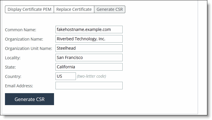
These configuration options are available:
Common Name (required)
Specifies the common name (hostname) of the peer.
Organization Name
Specifies the organization name (for example, the company).
Organization Unit Name
Specifies the organization unit name (for example, the section or department).
Locality
Specifies the city.
State
Specifies the state. Don’t abbreviate.
Country (2-letter code)
Specifies the country (2-letter code only).
Email Address
Specifies the email address of the contact person.
Generate CSR
Generates the Certificate Signing Request.
Managing web settings and web certificates
You configure web settings and web certificates in the Editing Appliance Configuration: <hostname>, Web Settings page.
This page applies to SteelHead and Interceptor.
Choose Manage > Topology: Appliances. Select the name of the appliance you want to edit to display the Edit Appliance tab, and then select the Appliance Pages tab to display the Appliance Configuration Pages list.
Under Appliance Configuration Pages, click Web Settings to display the Editing Appliance Configuration <hostname>, Web Settings page. These configuration options are available:
Default Web Login ID
Specifies the username that appears in the authentication page. The default value is admin.
Web Inactivity Timeout
Specifies the number of idle minutes before time-out. The default value is 15. A value of 0 disables time-out.
Allow Session Timeouts When Viewing Auto-Refreshing Pages
Stops the automatic updating of the report pages when the session times out. By default, session time-out is enabled. Clear the Allow box to disable the session time-out, remain logged in indefinitely, and automatically refresh the report pages.
Disabling this feature poses a security risk.
Managing web certificates
You can manage web certificates in the Web Settings page:
• View certificate details.
• View certificate in PEM format.
• Replace a signed certificate by importing a certificate and private key or generating a self-signed certificate and new private key.
• Generate a certificate signing request (CSR).
To manage web certificates, select the Details tab under Web Certificate. These identity certificate details are available:
Issued To/Issued By
• Common Name—Specifies the common name of the certificate authority.
• Email—Specifies the email.
• Organization—Specifies the organization name (for example, the company).
• Organization Unit—Specifies the organization unit name (for example, section or department).
• Locality—Specifies the city.
• State—Specifies the state.
• Country—Specifies the country.
Validity
• Issued On—Specifies the date the certificate was issued.
• Expires On—Specifies the date the certificate expires.
Fingerprint
Specifies the SSL fingerprint.
Key
• Type—Specifies the key type.
• Size—Specifies the size, in bytes.
To view the certificate in PEM format, under Web Certificate, select the PEM tab to display the certificate. The certificate appears in PEM format.
To replace an existing certificate, under Web Certificate, click Replace. These configuration options are available:
Import Certificate and Private Key
Imports the certificate and key. The page displays controls for browsing to and uploading the certificate and key files. You can also use the text box to copy and paste a PEM file. The private key is required regardless of whether you’re adding or updating the certificate.
Certificate
• Upload—Browse to the local file in PKCS-12, PEM, or DER formats.
• Paste it here (PEM)—Copy and then paste the contents of a PEM file.
Private Key
Specifies the private key origin. The Private Key is in a separate file (see below)—You can either upload it or copy and paste it. This file includes the Certificate and Private Key. The Private Key for this Certificate was created with a CSR generated on this appliance.
Separate Private Key
• Upload (PEM or DER formats)—Browse to the local file in PEM or DER formats.
• Paste it here (PEM only)—Paste the contents of a PEM file.
• Decryption Password—Specify the decryption password, if necessary. Passwords are required for PKCS-12 files, optional for PEM files, and never needed for DER files.
Import Certificate and Key
Imports the certificate and key.
Generate Self-Signed Certificate and New Private Key
Generates a new private key and self-signed public certificate. The page displays controls to identify and generate the new certificate and key:
• Organization Name—Specify the organization name (for example, the company).
• Organization Unit Name—Specify the organization unit name (for example, the section or department).
• Locality—Specify the city.
• State (no abbreviations)—Specify the state.
• Country (2-letter code)—Specify the country (2-letter code only).
• Email Address—Specify the email address of the contact person.
• Validity Period (Days)—Specify how many days the certificate is valid.
Private Key
• Cipher Bits—Select the key length from the drop-down list. The default is 1024.
Generate Certificate and Key
Generates CSR and private key.
To generate a CSR, under Web Certificate select Generate CSR. These configuration options are available:
Common Name
Specifies the common name (hostname).
Organization Name
Specifies the organization name (for example, the company).
Organization Unit Name
Specifies the organization unit name (for example, the section or department).
Locality
Specifies the city.
State
Specifies the state.
Country
Specifies the country (two-letter code only).
Email Address
Specifies the email address of the contact person.
Generate CSR
Generates the CSR.
Managing outbound QoS interfaces
You configure legacy outbound QoS interfaces for Basic and Advanced QoS in the Editing Appliance Configuration: <hostname>. Outbound QoS Interfaces page.
This feature applies to SteelHead.
For detailed information about QoS, see the SteelHead User Guide.
Perform this task to modify Outbound QoS (Basic) interface settings:
To modify Outbound QoS (Basic) interface settings, choose Manage > Topology: Appliances. Select the name of the appliance you want to edit to display the Edit Appliance tab, and then select the Appliance Pages tab to display the Appliance Configuration Pages list.
Under Appliance Configuration Pages, click Outbound QoS Interfaces to display the Editing Appliance Configuration: <hostname>, Outbound QoS (Basic) page. These configuration options are available under WAN Link:
WAN Bandwidth (kbps)
Specifies its bandwidth link rate in kilobits per second. The link rate is the bottleneck WAN bandwidth, not the interface speed out of the WAN interface into the router or switch. For example, if your SCC connects to a router with a 100-Mbps link, don’t specify this value; specify the actual WAN bandwidth (for example, T1 or T3). Different WAN interfaces can have different WAN bandwidths; you must enter the bandwidth link rate correctly for QoS to function properly.
Interfaces detected on the Appliance
Allows you to select the necessary check boxes.
Additional Interfaces
Allows you to select the necessary check boxes.
You can modify outbound QoS (advanced) interface settings under Manage > Topology: Appliances. Select the name of the appliance you want to edit to display the Edit Appliance tab. Select the Appliance Pages tab to display the Appliance Configuration Pages list.
Under Appliance Configuration Pages, select Outbound QoS Interfaces (Advanced) to display the Editing Appliance Configuration: <hostname>, Outbound QoS (Basic) page. Click Outbound QoS (Advanced) to display the Editing Appliance Configuration: <hostname>, Outbound QoS page.
These configuration options are available under WAN Link:
Interfaces detected on the Appliance
Allows you to select the necessary check boxes.
Additional Interfaces
Allows you to select the necessary check boxes.
Managing legacy inbound QoS interfaces
You configure legacy inbound QoS interfaces in the Editing Appliance Configuration: <hostname>. Outbound QoS Interfaces page.
This feature applies only to SteelHead.
For detailed information about QoS, see the SteelHead User Guide.
Choose Manage > Topology: Appliances. Select the name of the appliance you want to edit to display the Edit Appliance tab. Select the Appliance Pages tab to display the Appliance Configuration Pages list.
Under Appliance Configuration Pages, click Inbound QoS Interfaces to display the Editing Appliance Configuration: <hostname>, Inbound QoS Interfaces page. These configuration options are available under WAN Link:
WAN Bandwidth (kbps)
Specifies WAN interface bandwidth link rate in kilobits per second. The link rate is the bottleneck WAN bandwidth, not the interface speed out of the WAN interface into the router or switch. For example, if your CMC appliance connects to a router with a 100-Mbps link, don’t specify this value; specify the actual WAN bandwidth (for example, T1 or T3). Different WAN interfaces can have different WAN bandwidths; you must enter the bandwidth link rate correctly for QoS to function properly.
Interfaces detected on the Appliance
Allows you to select the necessary check box(es).
Additional Interfaces
Allows you to select the necessary check box(es).
Managing path selection
You configure legacy path selection rules in the Editing Appliance Configuration: <hostname>, Path Selection page.
You can’t migrate your previously defined path selection rules to SCC 9.0 or later.
This page applies to SteelHead.
To add a new path, choose Manage > Topology: Appliances. Select the name of the appliance you want to edit to display the Edit Appliance tab. Select the Appliance Pages tab to display the Appliance Configuration Pages list.
Under Appliance Configuration Pages, click Path Selection to display the Editing Appliance Configuration: <hostname>, Path Selection page. Click + Add a New Path to expand the page. These configuration options are available:
Name
Specifies the path selection name.
The path selection name is case sensitive and must match the path name in the policy being pushed to this appliance. If the names don’t match, policy push will fail.
Gateway IP Address
Specifies the IP address for the gateway. The gateway must be in the same network as the in-path interface.
The gateway IP address must be in the same subnet (local network) as the in-path interface.
Interface
Specifies a relay interface over which the appliance reaches the path.
Tunnel Mode
Specifies the tunnel mode from the drop-down list: None or GRE. GRE provides IPv4 generic routing encapsulation (GRE) for direct uplinks. Direct uplinks using GRE become direct tunneled uplinks. You must create direct tunneled uplinks to steer traffic over any uplink that traverses a stateful firewall between the SteelHeads.
Without GRE, traffic attempting to switch midstream to an uplink that traverses a stateful firewall might be blocked. The firewall needs to track the TCP connection state and sequence numbers for security reasons. Because the firewall hasn’t logged the initial connection handshake, and has partial or no packet sequence numbers, it blocks the attempt to switch to the secondary uplink and might drop these packets. To traverse the firewall, path selection can encapsulate that traffic into a GRE tunnel.
Add
Adds the path to the path table. The SCC redisplays the path table and applies your changes to the running configuration, which is stored in memory.
Managing connection forwarding
You configure connection forwarding for a network with multiple paths from the server in the Editing Appliance Configuration: <hostname>, Connection Forwarding page.
You enable connection forwarding only in asymmetric networks; that is, networks in that a client request traverses a different network path than the server response. The default port for connection forwarding is 7850.
This feature applies to SteelHead.
For detailed information about connection forwarding, see the SteelHead User Guide.
To configure connection forwarding, choose Manage > Topology: Appliances. Select the name of the appliance you want to edit to display the Edit Appliance tab. Select the Appliance Pages tab to display the Appliance Configuration Pages list.
Under Appliance Configuration Pages, click Connection Forwarding to display the Editing Appliance Configuration: <hostname>, Connection Forwarding page. These configuration options are available under Connection Forwarding Settings:
Enable Connection Forwarding
Enables connection forwarding by default on all neighbors added to the peer list. The default value is 7850.
Port
Specifies the port number to use as the default for the neighbor SteelHead in-path port. The default value is 7850.
Keep-Alive Interval
Specifies the number of seconds to use as the default interval for ping commands between neighbor SteelHeads. The default value is 1 second.
Keep-Alive Count
Specifies the number of tries to use as the default number of failed ping attempts before an appliance terminates a connection with a neighbor. The default value is 3.
In-Path Neighbor Failure
Uses the neighbor appliance to optimize new connections if the appliance fails.
For in-path deployments that use connection forwarding with WCCP, enabling this option ensures that if one appliance fails, the neighbor appliance continues to optimize new connections.
For in-path deployments that use connection forwarding without WCCP, enabling this option ensures that a SteelHead attempts to optimize new connections that are symmetrically routed, even after all of the neighbor SteelHeads on another network path failed. New asymmetrically routed connections aren’t optimized but passed through.
Multiple Interface Support
Enables high availability on SteelHeads configured with multiple in-path interfaces and using connection forwarding with another multiport SteelHead. This option makes all neighbor in-path interface IP addresses visible to each peer to ensure proper neighbor communication if the in-path0_0 interface fails.
RiOS 6.5 and later require connection forwarding in a WCCP cluster. You must enable multiple interface support for a connection-forwarding neighbor to work with IPv6.
IPv6 Connection Forwarding
Enables IPv6 connection forwarding mode. Enabling this option disallows IPv4 addresses for neighbors.
These configuration options are available under Neighbor Table:
+ Add a New Neighbor
Displays the controls to add a new neighbor.
Hostname
Specifies a hostname.
In-Path IP Address
Specifies the in-path IP address for the neighbor SteelHead. When you define a neighbor, you must specify the appliance in-path IP address, not the primary IP address. Either IPv4 or both IPv4 and IPv6 can be specified. To use connection forwarding with IPv6, both SteelHeads must be running RiOS 8.5 or later and you must enable multiple interface support.
Port
Specifies the in-path port for the neighbor SteelHead. The default port is 7850.
Additional IP Addresses
Adds a neighbor SteelHead to the neighbor list.
Add
Adds a new neighbor.
Managing web proxy cache settings
You can configure the web proxy cache size for VCX-10 to VCX-90 SteelHeads in the Editing Appliance Configuration: <hostname>, Web Proxy Settings page.
You can configure the total cache size in the SCC Web Proxy Settings page for the managed VCX-10 to VCX-90 models.
If you make a change to the web proxy cache size and web proxy is running, the web proxy is automatically restarted.
Any changes to an already configured web proxy cache size will purge the cache. We recommend that you make changes to the web proxy cache size cautiously.
Disabling web proxy on VCX models will disable all web proxy alarms but it will not affect the existing cache.
This feature applies only to SteelHead VCX-10 to VCX-90 models.
For more about web proxy, see
About Web Proxy. and the
SteelHead User Guide.
To configure web proxy cache settings, choose Manage > Topology: Appliances. Select the VCX appliance you want to edit to display the Edit Appliance tab. Select the Appliance Pages tab to display the Appliance Configuration Pages list.
Under Appliance Configuration Pages, click Web Proxy Settings to display the Editing Appliance Configuration: <hostname>, Web Proxy Cache Settings page. These configuration options are available under Web Proxy Cache Settings:
Min. Cache Size
Specifies the minimum web proxy cache size in gigabytes (GB), as specified by the license. The minimum cache size is 5 GB. This value is updated after a policy push or a change is detected in the license.
Max. Cache Size
Specifies the maximum cache size in gigabytes (GB), as specified by the license. This value is updated after a policy push or a change is detected in the license. The maximum cache size is 800 GB, depending on the available disk size and your license maximum size. The maximum cache size can’t exceed the available disk space. If you exceed the available disk space, an alarm is triggered.
Actual Cache Size
Specifies the disk space used by the current web proxy cache. This value is updated after a policy push or a change is detected in the license. The actual disk size differs if the cache size isn’t configured or if the disk doesn’t have enough disk space for the configured cache size.
Cache Size
Specifies the total cache size in gigabytes (GB). This value is your configured cache size. If the configured cache size is larger than what the management disk can support (that is, the actual cache size) then an alarm is raised.
Managing SAML
You can enable SAML on a single appliance using the SAML page of that appliance, or you can configure SAML in a policy and then push the policy across multiple appliances.
Before you enable SAML on a single appliance or on multiple appliances, you must configure IdP individually for each appliance because the IdP metadata required to enable SAML is unique for each appliance.
Basic steps to configure SAML as a policy
Task | Reference |
|---|
1. Download the metadata of the appliance from the appliance’s management console. | SteelHead User Guide |
2. Configure the appliance in the IdP website. | SteelHead User Guide |
3. Paste the metadata you received from the IdP website in the SCC Management Console. Optionally, if you want to check whether your IdP configuration is valid or not, paste the metadata in the appliance’s Management Console instead. After you validate the metadata, fetch the appliance-specific configuration from SCC. |
SteelHead User Guide
|
4. Repeat steps 1 through 3 for all the appliances on which you want to perform the policy push. | |
5. Configure SAML in the policy pages and push the policy across all the appliances. | |
For detailed information, see the SteelHead User Guide.
Configuring IdP in SCC
You can configure IdP in the Editing Appliance Configuration: <hostname>, SAML page.
Choose Manage > Topology: Appliances to display the Appliances page. Select the name of the appliance you want to edit to display the Appliance Pages tab. Select the Appliance Pages tab to display the Appliance Configuration Pages list.
Under Appliance Configuration Pages, click SAML to display the Editing Appliance Configuration: <hostname>, SAML page. Click Include to include this configuration from the policy push for the specified appliance. Your changes aren’t applied to the specified appliance until the policy is pushed to the appliance. Under IdP Configuration, paste the IdP metadata you received from the IdP website, and click Apply.
You have completed IdP configuration that is specific to an appliance. You can now create a policy to configure and enable SAML. This policy can be pushed to an appliance of your choice or to a group of appliances.
Creating a SAML authentication policy
Choose Manage > Policies. Click + Add Policy to expand the page. Type a policy name and description and click Add to display the Editing Policy page.
Click + Add/Remove Pages to display the Add/Remove Policy Pages pop-up window. Under Security, select SAML and click Apply to display the Editing Policy page. In the Editing Policy page, click SAML to display Editing <policy-name> page. Click Include to include the policy in the policy push.
Editing the policy
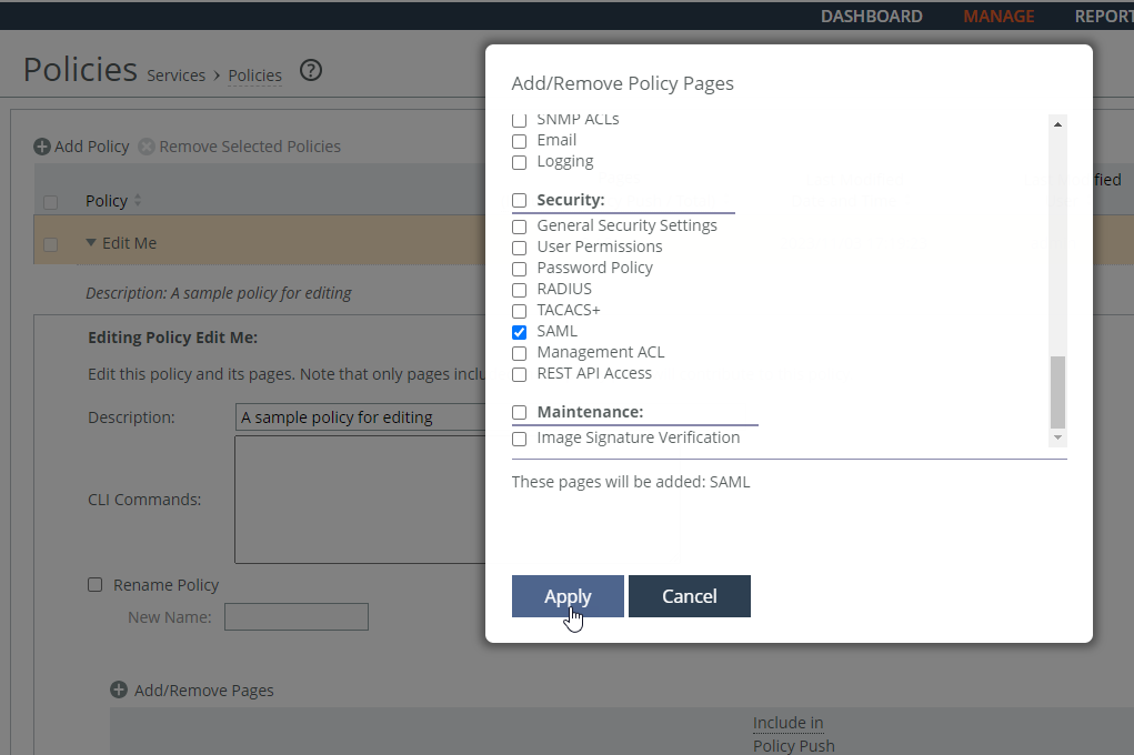
These SAML request and response settings are available under IdP Configuration:
IdP Metadata
Allows you to paste the IdP metadata you copied or received from the IdP website.
Security Settings
• Sign Authentication Request—Select this option to have SCC sign the SAML authentication request sent to the identity provider. Signing the initial login request sent by SCC allows the identity provider to verify that all login requests originate from a trusted service provider.
• Requires Signed Assertions—Select if SAML assertions must be signed. Some SAML configurations require signed assertions to improve security.
• Requires Encrypted Assertions—Select this option to indicate to the SAML identity provider that SCC requires encrypted SAML assertion responses. When this option is selected, the identity provider encrypts the assertion section of the SAML responses. Even though all SAML traffic to and from SCC is already encrypted by the use of HTTPS, this option adds another layer of encryption.
Attribute
• User Name Attribute—Enter the name of the IdP variable that carries the username of the user. The username attribute is mandatory and must be sent by your identify provider in the SAML response to align the login with a configured SteelHead account. The default value is samlNameId.
• Member of Attribute—Enter the name of the IdP variable that carries the role of the user. The default value is memberOf.
Under IdP Configuration, configure the SAML request and response settings:
IdP Metadata
Pastes the IdP metadata you copied or received from the IdP website.
Security Settings
• Sign Authentication Request—Select this option to have SCC sign the SAML authentication request sent to the identity provider. Signing the initial login request sent by SCC allows the identity provider to verify that all login requests originate from a trusted service provider.
• Requires Signed Assertions—Select if SAML assertions must be signed. Some SAML configurations require signed assertions to improve security.
• Requires Encrypted Assertions—Select this option to indicate to the SAML identity provider that SCC requires encrypted SAML assertion responses. When this option is selected, the identity provider encrypts the assertion section of the SAML responses. Even though all SAML traffic to and from SCC is already encrypted by the use of HTTPS, this option adds another layer of encryption.
Attribute
• User Name Attribute—Enter the name of the IdP variable that carries the username of the user. The username attribute is mandatory and must be sent by your identify provider in the SAML response to align the login with a configured SteelHead account. The default value is samlNameId.
• Member of Attribute—Enter the name of the IdP variable that carries the role of the user. The default value is memberOf.
Click Apply to save your configuration settings. Under SAML, to enable SAML, select the Enable SAML check box and click Apply. Click Save to Disk to save you settings permanently.
Choose Manage > Topology: Appliances to return to the Appliances page. Click Appliance Operations to expand the page. Select the appliance you want to push, select Push Policies from the drop-down list, and click Push.
Pushing policies to appliances
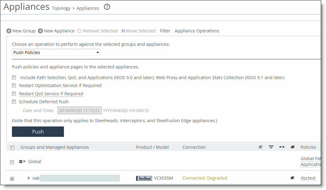
Choose Manage > Operations: Operations History to verify that the operation was successful.
Logging
Settings are similar to those described in the section on remote log servers.