About Sites, Networks, Uplinks, and Regions
The SCC's hybrid networking management system uses sites, networks, uplinks, and regions to manage the topology of interconnected Riverbed appliances. This hybrid architecture combines private networks, like MPLS-based WANs, with public services such as the internet. Riverbed appliances help control network usage by applying application-level QoS and WAN path selection, prioritizing critical and latency-sensitive applications while reducing usage by nonessential ones.
Currently, hybrid networking features do not support IPv6. The SCC allows you to configure network topologies and application policies according to your business needs. These settings are the foundation for configuring core features in a hybrid network, including QoS, path selection, secure transport, and web proxy. For example, SCC uses the topology definition to:
• share the remote site information between peers.
• determine possible remote paths for path selection.
• precompute the estimated end-to-end bandwidth for QoS, based on the remote uplinks.
A network topology includes these WAN topology properties:
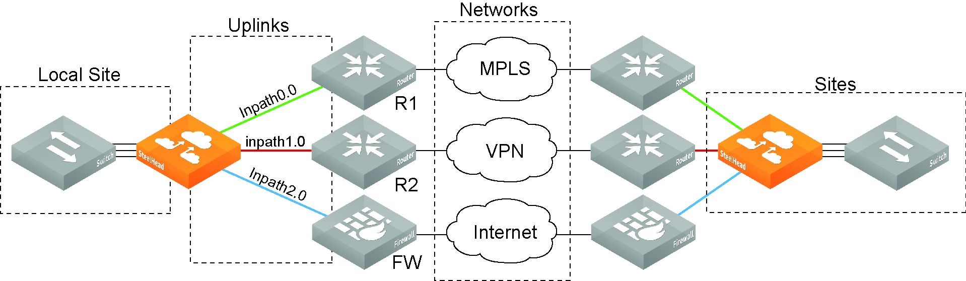
• Networks—The networks represent the WAN clouds that sites and site types use to communicate to each other using Primary MPLS, VSAT, or the internet. Basically, a network connects two uplinks between two sites. The SCC creates two nonsecure networks: MPLS and Internet. You can create additional secure and nonsecured networks or rename the precreated networks based on your topology requirements. You can also configure the Max Backoff Interval for a network to improve path selection performance. If there is no traffic at a site, the Max Backoff Interval default value of 1800 seconds determines how often that uplink is probed. Networks are important for path selection and secure transport. For details, see
About networks. • Sites—Define the discrete physical locations of Riverbed appliances in the network (for example, a branch office or data center) so that you can more easily configure and manage those areas of your network. A site is a logical grouping of subnets and represents the physical and logical topology of a site type. You classify traffic for each site using IP addresses. Sites are linked to one or more networks. The local sites use the WAN in the network definition to connect to the other sites. The default site is a catch-all site that’s the only site needed to backhaul traffic. Sites are used with the path selection, QoS, and secure transport features. For details, see
• Site Types—Groups one or more sites based on common attributes, such as business function and size. Riverbed automatically creates the basic site types: Data Center, Branch, and Headquarters. Site types are the building blocks for QoS profiles and pushing 9.0 and later features to SteelHeads. For details, see
About site types. • Uplinks—Define the last network segment connecting the local site to a network. You define carrier-assigned characteristics to an uplink: for example, the upload and download bandwidth and latency. An uplink must be directly (L2) reachable by at least one SteelHead or Interceptor in the local network. An uplink doesn’t need to be a physical in-path connection. Path selection uses only local uplinks. SteelHeads deployed in hybrid networks send ICMP probes on uplinks to establish contact with the appliances in the network. This uplink probing frequency can affect the scaling and performance of hybrid networks. Path selection rule-aware probing improves deployment scalability of hybrid networking. For details, see
About uplinks. • Uplink Types—An uplink type is a name for similar functioning uplinks. On the SCC, uplink types can be used across multiple sites and path selection rules can be created using these names. The name must be unique at a site (but it can be same across different sites) so that the system can detect which path selection rule uses which uplinks. Because path selection rules are global on the SCC, you’re restricted to eight uplink types. Uplink types are the building blocks for path selection. For example, you can label uplink types as primary, secondary, and tertiary based on the path selection preference. The uplink type can be based on the type of interface or network resource, such as Verizon or global resource of uplink abstraction that’s tied to a network. On the SteelHead, this field is called
Uplink Name; on the SCC it is
Uplink Type. For details, see
About uplink types. • Regions—Groups of sites based on a geographic location, such as North America, Europe, and so on. Regions are particularly important in reporting. Regions help you to troubleshoot network issues. For details, see
About site regions. Network topology
A site completes the topology by informing the appliances of what subnets reside at that location and what appliances are associated with them. After your appliances are registered in the SCC, you create a site and select the appliances to be a part of the site. You should add all remote sites in your network even if there is no other Riverbed appliance associated with them.
If you have to manage legacy QoS and path selection configuration settings, this is an old policy push as opposed to the new hybrid policy push. If you have a mixed network where you’re managing legacy QoS and path selection settings and new ones, you will have to maintain two sets of configuration settings. You can still add appliances to a site even though they’re not receiving new hybrid configuration settings.
Before you start defining your network topology in SCC:
• gather existing appliance group names and the appliance information (such as IP address and serial number) that belong to them. Often, existing appliance groups correspond to a particular location—these appliances populate your sites in your network topology.
• Determine which appliances and subnets are associated with which sites in your network. Sites are essential to managing QoS, path selection, secure transport, application statistics, and web proxy.
• Create a network deployment diagram to help you identify networks, sites, and uplinks.
About networks
You define networks under Manage > Topology: Sites & Networks. On the Sites & Networks page, you enable a specific network to be securable; that is, to encrypt traffic for secure transport. You can only define secure networks on the SCC; you can’t define secure networks on the SteelHead.
Networks represent the WAN clouds that sites and site types use to communicate to each other using Primary MPLS, VSAT, or the internet. Essentially, a network connects two uplinks between two sites.
Networks are very important for path selection and secure transport. A secure network is specifically used for the secure transport. The SCC creates two nonsecure networks: MPLS and Internet. You can create additional secure and nonsecured networks or rename the precreated networks based on your topology requirements.
For secure transport, you must specify that a network is securable to ensure that the network is part of the secure transport group. A secure transport group is a set of SteelHeads that share the same cryptographic keys and have connectivity to each other. Any member of the secure transport group can create a tunnel to any other member of the same group instantaneously, without delay. The traffic doesn’t incur any added latency waiting for the tunnels to establish. For detailed information about configuring secure transport, see
Managing secure transport.You can specify a secure transport concentrator if you don’t want to overload your SteelHead in the demilitarized zone (DMZ) so that you can perform secure transport or if you want to off load secure transport to be done for internet-bound traffic only. For detailed information, see
Configuring secure transport concentrators.Traffic aware backoff probing
With RiOS 9.2 and SCC 9.2 or later, SteelHeads with path selection enabled automatically perform Traffic Aware Backoff Probing. SteelHeads gradually reduce probing frequency to remote sites that have no traffic, from the default rate of every 2 seconds down to the default Max Backoff interval of every 1800 seconds. You configure the Max Backoff Interval when you define a network on the SCC.
You can change the Max Backoff Interval using the SCC to whatever value is best suited for your network environment.
On the SteelHead, you can view the back-off probe setting using the show path-selection debug networks CLI command.
For detailed information about improving hybrid scaling probing techniques using the Max Backoff Interval in Networks, see
Managing path selection.Configuring networks
You can configure networks under Manage > Topology: Sites & Networks. The Sites & Networks page displays the predefined networks appear: MPLS and Internet. You can edit or delete these networks. The SCC doesn’t automatically link default uplinks to these networks. Click + Add a Network to display the New Network pop-up window. These configuration options are available:
Network Name
Specifies the network name: for example, AT&T or MPLS. The network name must be unique and can’t contain spaces or special characters.
Securable using Secure Transport
Specifies whether this network is securable using secure transport. To enable secure transport, you must specify that a network is securable to ensure that the network is part of the secure transport group. A member of the secure transport group can create a secure path to any other member of the same group instantaneously, without delay. Select public if you want to use UDP encapsulation on the secure traffic using the port number defined for the in-path interface.
The secure transport service enables group encryption for path selection deployments. RiOS adds all appliances having a secured uplink to a secure transport group. You can secure traffic flowing between any two appliances in the secure transport group by directing it to a secured uplink using path selection service rules. Secure transport uses UDP to encapsulate traffic on a public network.
Public Network
Indicates if the network represents the internet.
Max Backoff Interval
Specifies the maximum time, in seconds, that the system backs off probing to sites in case there is no traffic. The default value is 1800 seconds. Uplinks to a remote site are probed at the uplink Timeout default rate of 2 seconds only if there is traffic at the site or if there is path failover, otherwise probing is backed off using the Max Backoff Interval. For the initial configuration push, the probes occur at the default rate of 1800 seconds. After that, the probes occur according to the values you have set for the Max Backoff Interval and the uplink’s Timeout field.
Configuring secure networks
You can configure secure networks under Manage > Topology: Sites & Networks.
• Click + Add a Network to display the New Network pop-up window.
• Specify a network name, select Securable using Secure Transport to ensure that the network is part of the secure transport group, and click Save.
• Under Sites, select the site you want to associate with the secure network and click Edit Site to display the Edit a Site pop-up window.
• To associate a new site, click + Add a Site to display the Edit a Site pop-up window and specify the site name, type, and region.
• Under Uplinks, click
+ Add a New Uplink and select the secured network from the Network drop-down list. Define the remaining parameters for the uplink. For details, see
About uplinks. • Click Save to save your settings.
About sites
You define sites in the Sites & Networks page and are essential for hybrid networking features like QoS, path selection, secure transport, application statistics, and web proxy. SCC 9.5 and later versions support up to 1000 sites.
You can migrate appliances to sites using the bulk import method or manually. For bulk migration, you can download a text file, fill it out, and upload it.
A site is essentially a grouping of subnets, representing both the physical and logical structure of a site type, such as a data center or various sizes of branch offices. Traffic is classified for each site using IP addresses. Sites manage how traffic flows through SteelHeads, with their properties influencing both behavior and location.
When creating a site in the SCC, it’s important to assign all SteelHeads to that site, whether it's a parallel or serial deployment, or even no SteelHeads if necessary. After a state migration or RMA operation, you will need to manually add the appliance back to the site where it was originally located. Additionally, if the appliance being replaced was a secure transport concentrator, its configuration needs to be manually updated as well.
Custom probe IP addresses
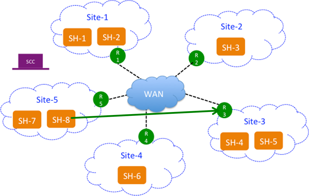
Path selection users can configure custom probe IP addresses for each site to specify specific endpoints to be probed for path availability. By default, the SCC uses the SteelHead in-path interfaces as probe endpoints, but with a custom probe, users can direct the SteelHeads to probe an IP address of their choice, such as a router, switch, or other system within the site.
Each SteelHead typically probes its neighbors within the site every 2 seconds by default. When a custom probe is configured, SteelHeads will instead probe the defined endpoint IP addresses.
This feature is especially useful for service-sensitive path selection deployments. It helps distinguish between accurate path availability and false positives or incorrect assumptions about service availability. By configuring custom probes, you ensure that only the specified endpoints need to be reachable for the path to be considered available.
This figure shows SteelHead-8 (SteelHead-8) probing the endpoint (R-3) in Site-3 rather than the SteelHeads located in the site: that is, SteelHead-4 and SteelHead-5.
SteelHead (SH 8) probing an endpoint (R3) in Site3
If the endpoint supports GRE encapsulation, then the probe will be successful from the other sites, otherwise the probes will fail.
If custom endpoints aren’t specified, then the SCC pushes the in-path interfaces as peers on the SteelHeads and vice a versa.
This feature is optional.
Where is the Local Site field in the SCC?
The SteelHead Local Site field is replaced by the Site Name field in the SCC. The SCC field has a different name because the SCC pushes the configuration settings relative to the SteelHead receiving the push. In other words, you have specified in the SCC which SteelHead belongs to that site and you push that information to the specified SteelHead. The SteelHead Local Site field is renamed automatically.
What happened to the Default Site in the SteelHead?
The SteelHead Default Site is renamed to the site you specified as a recipient of the backhaul traffic in the SCC. In the SteelHead, the default site owns the all zero destination network (that is, 0.0.0.0), eliminating the need to configure every single internet subnet. In the SCC, you can’t build a site and give it the 0.0.0.0 subnet because once the configuration is pushed to the SteelHead the 0.0.0.0 subnet belongs to the site that traffic is being backhauled to, which is the default site.
Why is there no peer IP address field in the SCC?
There is no field for the peer IP address to probe on the SCC because the SCC automatically fills in this value with the SteelHead in-path IP addresses. The SCC uses the SteelHead in-path IP addresses that you have associated to that site. If no SteelHead is assigned to that site, the default gateway is used. This is only relevant to path selection configurations.
What is the Internet Traffic field used for?
For path selection, the most important setting in a site is the Internet Traffic field. This field functions differently on the SteelHead. In the SCC, you specify how internet-bound traffic is routed. You can choose Direct to Internet if you’re putting public internet traffic directly at the site. Direct to Internet traffic sends all traffic with an unknown destination to the specified default gateway.
Your other choice is Backhaul through Site. Configure this option if you have to send your traffic back through a specific site, typically the data center. The Backhaul through Site option sends all traffic to whatever site you specify in this field and this becomes the default site on the SteelHead. On the SteelHead, the default site is automatically renamed after you push your settings, so you don’t have to configure the default site on the SteelHead. You simply specify it on the SCC.
As a best practice, always configure the data center first.
Configuring sites
You can configure sites under Manage > Topology: Sites & Networks. Click + Add a Site to display the pop-up window. These configuration options are available:
Basic Information
Specifies the basic information for the site:
• Site Name—Specify the name of the site: for example, DCEurope. Site names should reflect the location or region so that you can track issues. The site name must be unique and can’t contain special characters. Site names can contain spaces.
• Site Type—Specify the site type. The basic site types are predefined: Data Center, Branch, and Headquarters. A maximum of 16 site types can be defined.
• Region—Specify the region in which the site is located. Regions help in reporting and troubleshooting problems.
• Description—Optionally, provide the intent of this site so that others can easily understand what this site is used for.
A new site type and site region are created when the site is created.
Contact Information
Specifies the contact information for the site:
• Name—Specify the name of the person responsible for the site.
• Job Title—Specify the job title for the person responsible for the site.
• Email—Specify the email address for the contact person for the site.
• Address—Specify the address for the site.
• City/Town—Specify the city or town for the site.
• State/Province—Specify the state or province for the site.
• Country—Specify the country the site.
Riverbed Appliances
Specifies the connection information for Riverbed peers for the site:
• Add Appliance—Specify the hostname or serial number for the site peer. You must enter each peer separately. The peer must be registered (that is, added as an appliance) in SCC.
When you add a site in the SCC you don’t have to specify the IP addresses of the SteelHeads at each given site because the SCC dynamically adds them to the site configuration that it sends to the SteelHeads.
Custom Probe Endpoint
Allows path selection users to specify, on a per site basis, specific endpoints to be probed to determine path availability rather than having the SCC automatically use that site's SteelHead in-path interfaces as probe endpoints. For service sensitive path selection deployments, custom-probe endpoints can better distinguish between true path availability versus false positives or inaccurate assumptions of service availability. You use the custom probe feature to define, on a per site basis, IP addresses that must be available for a path to be considered available to use. IP addresses must be separated by a comma or semicolon.
Network Information
Specifies the subnets for the site. Separate subnets with a comma, a semicolon, or a new line. You must list all the subnets either manually or copy and paste them from a spreadsheet.
Internet Traffic
(Use only when path selection is enabled.) Specifies how internet access is achieved at this site.
• Direct to Internet—Traffic is sent based on path selection rules configured. Typically, the data center is specified as Direct to Internet because it isn’t backhauling traffic through any remote branches.
• Backhaul through site—Specify the subnet to backhaul traffic through the site. All out-bound traffic is sent or relayed to the specified site, no matter what path selection rule is configured. The backhaul traffic option sends all unknown traffic to whatever site you choose in this field—this becomes the default site on the SteelHead. On the SteelHead, the default site is automatically renamed after you push your settings. You don’t need to configure the default site on the SteelHead. You simply choose it on the SCC.
Uplinks
• Click
+ Add New Uplink to display the controls. For detailed information, see
Configuring uplinks.
• Alternately, you can select a site connectivity template from the drop-down list if you have configured one. For detailed information about configuring a site connectivity template, see
Configuring site connectivity templates.
About site connectivity templates
You define site connectivity templates in the Sites & Networks page.
A site connectivity template is a configuration tool used to define common uplink properties that apply across multiple sites. You create these templates in the Sites & Networks page. If you have several sites with similar uplinks, using a site connectivity template helps streamline the setup by defining shared uplink properties once and applying them to multiple sites.
When you apply a site connectivity template to a site, the uplinks from the template are copied to the site. However, any changes to the template won’t affect sites that have already received the template’s uplinks. After applying the template, you can still configure site-specific settings for the uplinks.
Site connectivity templates are helpful for defining consistent configurations across multiple sites. For example, when adding a SteelHead to a new site, you can use a template to quickly apply the same settings. The template can also include a description, which is useful for new network administrators, ensuring they understand the configuration's purpose and usage.
Configuring site connectivity templates
You can configure site connectivity templates under Manage > Topology: Sites & Networks. Click Add a Template to display the New Site dialog box and scroll down to the Add Uplinks panel. These configuration options are available:
Name
Specifies the name for the template. The name must be unique and can’t contain spaces or special characters.
Add New Uplink
Expands the panel by clicking the plus sign (+).
Network
Selects the network from the drop-down list.
Uplink Type
Specifies a name for similar functioning uplinks. On the SCC, uplink types can be used across multiple sites and path selection rules can be created using these names. The name must be unique at a site (but it can be same across different sites) so that the system can detect which path selection rule uses which uplinks. Because path selection rules are global on the SCC, you’re restricted to eight uplink types. (On the SteelHead, this field is called Uplink Name; on the SCC it is Uplink Type.)
Uplink types are the building blocks for path selection. For example, you can label uplink types as primary, secondary, and tertiary based on the path selection preference. The uplink type can be based on the type of interface or network resource, such as Verizon or global resource of uplink abstraction that’s tied to a network.
In-Path Interface
Specifies the in-path interface that relays traffic from for the uplink from the drop-down list:
• Is Default for inpath0_0—Specify to make this interface the default uplink to relay traffic through the selected interface. The SCC allows you to add many uplinks tied to the same in-path interface, or virtual uplinks. The SCC doesn’t know which of these uplinks will be the default uplink. This option enables you to specify which in-path interface should be used as the default uplink
• Enable GRE Tunneling—Specify for SteelHeads that are behind a firewall to provide IPv4 generic routing encapsulation (GRE) for direct uplinks used in path selection. Direct uplinks using GRE become direct tunneled uplinks. You must create direct tunneled uplinks to steer traffic over any uplink that traverses a stateful firewall between a server-side SteelHead and a client-side SteelHead. Without GRE, traffic attempting to switch midstream to an uplink that traverses a stateful firewall might be blocked. The firewall needs to track the TCP connection state and sequence numbers for security reasons. Because the firewall hasn’t logged the initial connection handshake, and has partial or no packet sequence numbers, it blocks the attempt to switch to the secondary uplink and might drop these packets. To traverse the firewall, path selection can encapsulate that traffic into a GRE tunnel. For details about firewalled path selection deployments, see the SteelHead Deployment Guide.
Bandwidth Up
(Applicable only for QoS deployments.) Specifies the bandwidth up value in kilobits per second. RiOS uses the bandwidth to precompute the end-to-end bandwidth for QoS. The SteelHead automatically sets the bandwidth for the default site to this value.
The uplink rate is the bottleneck WAN bandwidth, not the interface speed out of the WAN interface into the router or switch. For example, if your SteelHead connects to a router with a 100-Mbps link, don’t specify this value—specify the actual WAN bandwidth (for example, T1 or T3).
Different WAN interfaces can have different WAN bandwidths; you must enter the bandwidth link rate correctly for QoS to function properly.
Bandwidth Down
(Applicable only for QoS deployments.) Specifies the bandwidth down value in kilobits per second. RiOS uses the bandwidth to precompute the end-to-end bandwidth for QoS. The SteelHead automatically sets the bandwidth for the default site to this value.
The uplink rate is the bottleneck WAN bandwidth, not the interface speed out of the WAN interface into the router or switch. For example, if your SteelHead connects to a router with a 100-Mbps link, don’t specify this value—specify the actual WAN bandwidth (for example, T1 or T3).
Different WAN interfaces can have different WAN bandwidths; you must enter the bandwidth link rate correctly for QoS to function properly.
Probe Settings
Specifies the probe settings for path selection monitoring. The SCC uses ICMP pings to monitor the uplink state dynamically. If one uplink fails, traffic is redirected to the next available uplink. When the original uplink comes back up, the traffic is redirected back to it. Specify the probe settings for the uplink:
• DSCP—Select the DSCP marking for the ping packet. You must select this option if the service providers are applying QoS metrics based on DSCP marking and each provider is using a different type of metric. Path selection-based DSCP marking can also be used in conjunction with PBR on an upstream router to support path selection in cases where the SteelHead is more than a single L3 hop away from the edge router. The default marking is preserve. Preserve specifies that the DSCP level or IP ToS value found on pass-through and optimized traffic is unchanged when it passes through the SteelHead.
• Timeout—Specify how much time, in seconds, elapses before the system considers the uplink to be unavailable. The default value is 2 seconds. RiOS uses ICMP pings to probe the uplinks. If the probes don’t make it back within this time-out setting and the system loses the number of packets defined by the threshold value, it considers the uplink to be down and triggers an alarm.
• Threshold—Specify how many time-out probes the system must receive before the uplink is considered unavailable and an alarm is triggered; the default value is 3 failed successive packets. This value also determines how many probes the system must receive to consider the uplink to be available. RiOS uses ICMP pings to monitor uplink availability. If the ping responses don’t make it back within the probe time-out and the system loses the number of packets defined by this threshold, it considers the uplink to be down and triggers an alarm.
• Bandwidth—Specify the maximum probing bandwidth for this uplink.
You can increase the efficiency of probing by limiting the number of probes that occur per second on an uplink. In the SCC when you create an uplink you can enforce a bandwidth rate limit on all probes in Probe Settings: Bandwidth field. The default bandwidth is 128 kbps.
On the SteelHead, you can view your settings using the show path-selection debug uplinks CLI command.
Click the template name to display details about the template. Click + Add New Uplink to add additional uplinks to an existing template.
About site types
Site types are used to group sites based on business roles or functions. Riverbed provides three default site types: Data Center, Headquarters, and Branch. You can also create additional site types to fit your organization’s needs. When setting up a site, you must assign it a site type. Site types are essential for managing QoS profiles and deploying new features to SteelHeads in SCC version 9.0 and later.
Before migrating appliances or configuring QoS, you must first create the necessary sites and site types. When building QoS profiles, it’s best to select site types rather than individual sites to keep the configuration simple and scalable. A QoS profile contains rules and classes that apply to traffic between specific site types or individual sites. Use specific sites in QoS only when making exceptions. When you push a QoS profile, it only applies to the selected site types or sites included in that push. For detailed information about migrating QoS policies and configuring QoS, see
Managing QoS.The default site types (Data Center, Headquarters, and Branch) cannot be modified or deleted.
Configuring site types
You can configure site types under Manage > Topology: Sites & Networks. Under Site Types, click the arrow (>) to expand the page, and click the plus sign (+) to display the New Site Type pop-up window. These configuration options are available:
Site Type name
Specifies the name for the site type. The name must be unique and can’t contain special characters.
Description
Specifies a description for the site type. This description will help you make configuration changes and to associate issues with particular sites.
About site regions
Site regions are a group of uplinks in a particular location used for information filtering. Example site regions include North America, Europe, or Asia.
Site regions are basically a group of uplinks in a particular location. Site regions can help you configure groups of sites (that is, using site templates) and identify issues with sites.
Configuring site regions
You can configure site regions under Manage > Topology: Sites & Networks. Under Site Regions, click the arrow (>) to expand the page. Click the plus sign (+) to display the New Site Region dialog box. This configuration option is available:
Site Region
Specifies the region for the site. The name must be unique and can’t contain special characters.
About secure transport concentrators
Secure transport concentrators are auxiliary sites linked to a primary site that needs secure transport. These concentrators include only the appliances responsible for handling secure transport and must always be associated with a primary site. They inherit most settings from the primary site, and these settings are finalized when you perform a hybrid push from the Sites & Networks page.
Typically located in a data center, secure transport concentrators work alongside SteelHeads that manage path selection and QoS. All networks and uplinks connected to these concentrators are secured. The SCC designates these appliances within the site and automatically creates an auxiliary site labeled as a secure transport concentrator.
In backhaul scenarios, for example, a branch office encrypts internet-bound traffic and sends it to the data center. At the data center, the concentrator decrypts the traffic, applies path selection based on defined rules, and forwards it to the internet. This setup ensures secure, efficient routing of sensitive or public-bound data.
Best practices for creating secure transport concentrators
• Create a site for which you need secure transport, typically the data center. Define the topology for the site appropriately; that is, create secure networks and uplinks. Call this SiteA.
• Create a secure transport concentrator associated with SiteA. The SCC prompts you to add appliances and link them to the SiteA.
• You will inherit most of the properties of SiteA (that is, the linked site). You will be prompted to import uplinks from the linked site but only for secured networks. If there are no secure networks in the associated site then the SCC issues an error.
• The secure transport concentrator uplinks will change the gateway of the inherited uplinks. The other properties aren’t editable.
Configuring secure transport concentrators
You can configure secure transport concentrators under Manage > Topology: Sites & Networks. Click + Add a Site to display the pop-up window. Define the primary site, typically the data center.
Click Secure Transport Concentrator to expand the page. These configuration options are available:
Secure Transport Concentrator
Specifies the secure transport concentrator. Secure transport concentrators receive only the secure portion of the path selection policy. They perform dedicated encryption services for SteelHeads participating in hybrid networking.
• Add Appliance—Specify the appliance from the drop-down list to be the secure transport concentrator. In the text box, specify the hostname or serial number or IP address. The concentrators contain only appliances which will perform secure transport.
Secure Transport Concentrator Uplinks
Specifies the secure transport concentrator uplinks to connect this site to securable networks. At least one uplink, which is associated with a secure and public network, is required.
Click + Add New Uplink to display the controls for configuring uplinks. You can only specify the gateway IP address for this uplink. The remaining uplink attributes are inherited from the uplinks defined for the same site. These configuration options are available:
Network
Specifies the network name from the drop-down list: for example, MPLS. Each uplink must have a unique interface, gateway, and probe DSCP setting. A topology doesn’t allow duplicate uplinks.
Uplink Type
Specifies a name for similar functioning uplinks. On the SCC, uplink types can be used across multiple sites and path selection rules can be created using these names. The name must be unique at a site (but it can be same across different sites) so that the system can detect which path selection rule uses which uplinks. Because path selection rules are global on the SCC, you’re restricted to eight uplink types. Uplink types are the building blocks for path selection. For example, you can label uplink types as primary, secondary, and tertiary based on the path selection preference. The uplink type can be based on the type of interface or network resource, such as Verizon or global resource of uplink abstraction that’s tied to a network. (On the SteelHead, this field is called Uplink Name; on the SCC it is Uplink Type.)
Gateway IP
Specifies the gateway IP address.
In-Path Interface
Specifies the in-path interface that relays traffic from for the uplink from the drop-down list:
• Is Default for inpath0_0—Specify to make this interface the default uplink to relay traffic through the selected interface. The SCC allows you to add many uplinks tied to the same in-path interface, or virtual uplinks. The SCC doesn’t know which of these uplinks will be the default uplink. This option enables you to specify which in-path interface should be used as the default uplink
• Enable GRE Tunneling—Specify for SteelHeads that are behind a firewall to provide IPv4 generic routing encapsulation (GRE) for direct uplinks used in path selection. Direct uplinks using GRE become direct tunneled uplinks. You must create direct tunneled uplinks to steer traffic over any uplink that traverses a stateful firewall between a server-side SteelHead and a client-side SteelHead. Without GRE, traffic attempting to switch midstream to an uplink that traverses a stateful firewall might be blocked. The firewall needs to track the TCP connection state and sequence numbers for security reasons. Because the firewall hasn’t logged the initial connection handshake, and has partial or no packet sequence numbers, it blocks the attempt to switch to the secondary uplink and might drop these packets. To traverse the firewall, path selection can encapsulate that traffic into a GRE tunnel. For details about firewalled path selection deployments, see the SteelHead Deployment Guide.
Bandwidth Up
(Applicable only for QoS deployments.) Specifies the primary interface bandwidth up value in kilobits per second. RiOS uses the bandwidth to precompute the end-to-end bandwidth for QoS. The SCC automatically sets the bandwidth for the default site to this value.
The uplink rate is the bottleneck WAN bandwidth, not the interface speed out of the WAN interface into the router or switch. For example, if your SteelHead connects to a router with a 100-Mbps link, don’t specify this value—specify the actual WAN bandwidth (for example, T1 or T3).
Different WAN interfaces can have different WAN bandwidths; you must enter the bandwidth link rate correctly for QoS to function properly.
Bandwidth Down
(Applicable only for QoS deployments.) Specifies the primary interface bandwidth down value in kilobits per second. RiOS uses the bandwidth to precompute the end-to-end bandwidth for QoS. The SCC automatically sets the bandwidth for the default site to this value.
The uplink rate is the bottleneck WAN bandwidth, not the interface speed out of the WAN interface into the router or switch. For example, if your SteelHead connects to a router with a 100-Mbps link, don’t specify this value—specify the actual WAN bandwidth (for example, T1 or T3).
Different WAN interfaces can have different WAN bandwidths; you must enter the bandwidth link rate correctly for QoS to function properly.
Probe Settings
Specifies the probe settings for path selection monitoring. The SCC uses ICMP pings to monitor the uplink state dynamically. If one uplink fails, traffic is redirected to the next available uplink. When the original uplink comes back up, the traffic is redirected back to it. Specify the probe settings for the uplink:
• DSCP—Select the DSCP marking for the ping packet. You must select this option if the service providers are applying QoS metrics based on DSCP marking and each provider is using a different type of metric. Path selection-based DSCP marking can also be used in conjunction with PBR on an upstream router to support path selection in cases where the SteelHead is more than a single L3 hop away from the edge router. The default marking is preserve. Preserve specifies that the DSCP level or IP ToS value found on pass-through and optimized traffic is unchanged when it passes through the SteelHead.
• Timeout—Specify how much time, in seconds, elapses before the system considers the uplink to be unavailable. The default value is 2 seconds. RiOS uses ICMP pings to probe the uplinks. If the probes don’t make it back within this time-out setting and the system loses the number of packets defined by the threshold value, it considers the uplink to be down and triggers an alarm.
• Threshold—Specify how many time-out probes the system must receive before the uplink is considered unavailable and an alarm is triggered; the default value is 3 failed successive packets. This value also determines how many probes the system must receive to consider the uplink to be available. RiOS uses ICMP pings to monitor uplink availability. If the ping responses don’t make it back within the probe time-out and the system loses the number of packets defined by this threshold, it considers the uplink to be down and triggers an alarm.
• Bandwidth—Specify the maximum probing bandwidth for this uplink.
You can increase the efficiency of probing by limiting the number of probes that occur per second on an uplink. The default bandwidth is 128 kbps.
On the SteelHead, you can view your settings using the show path-selection debug uplinks CLI command.
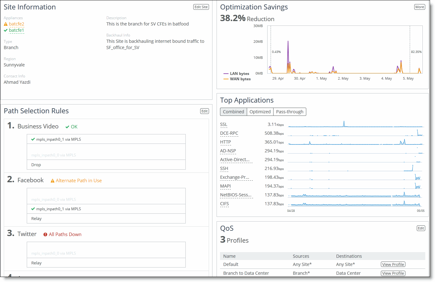
Viewing site details
You can view site details, including the appliance, optimization savings, reachability, site type, region, path selection rules, and QoS classes under Manage > Topology: Sites & Networks. Under Sites, scroll to the site you want to view and click View Site to display the Sites Details page. You can perform these actions:
• Edit site information.
• Edit path selection rules.
• View optimization savings.
• View application statistics. On the right side of the page, the throughput for the top ten applications is displayed.
• Edit QoS profiles.
• View sites reachability. Scroll to the bottom of the page to view site reachability.
Viewing sites details
Editing site details
You can edit site details under Manage > Topology: Sites & Networks. Under Sites, scroll to the site you want to edit and click
Edit Site to display the Edit a Site Details pop-up window. For detailed information about site controls, see
About sites.About uplinks
An uplink is the final network segment that connects a local site to a network. You can define multiple uplinks for a single network, giving the system flexibility to choose the best path for traffic. The SteelHead monitors uplink status and selects the most appropriate path for each packet, which helps optimize network usage and control. Uplinks are essential for building your network topology.
Uplinks are also important for QoS, as they specify available bandwidth for remote sites. This bandwidth is used by RiOS to calculate the bottleneck bandwidth across the full path.
Each uplink can be defined by its outgoing interface and, optionally, a next-hop gateway IP. You can assign different DSCP marks to flows on each uplink, allowing routers to prioritize traffic based on these marks.
The probing frequency of uplinks affects hybrid network scalability and performance. SteelHeads probe more frequently when a site has traffic and back off when there's no activity. By default, uplinks are probed every 2 seconds if traffic is present. If not, probing slows to a default Max Backoff Interval of 1800 seconds, which you can adjust per your network needs.
If probe responses are not received within the timeout period, the system marks the probe as lost. After missing a set number of probes (defined by a threshold), the uplink is considered down, and an alert is triggered. The SteelHead automatically reroutes traffic to another available uplink. Once the failed uplink recovers, traffic is redirected back to it.
Path selection only uses local uplinks. To simplify configuration across similar sites, you can use site connectivity templates—predefined sets of uplinks that can be cloned and reused at multiple locations. This is helpful for branch offices or other sites with the same uplink structure.
For details about site templates, see
About site connectivity templates.Configuring uplinks
You can configure uplinks under Manage > Topology: Sites & Networks. Click + Add a Site and scroll down to the Add Uplinks. Click + Add a New Uplink to expand the page. These configuration options are available:
Network
Specifies the network name from the drop-down list: for example, MPLS.
Uplink Type
Specifies a name for similar functioning uplinks. (On the SteelHead, this field is called Uplink Name; on the SCC it is Uplink Type.) On the SCC, uplink types can be used across multiple sites and path selection rules can be created using these names. The name must be unique at a site (but it can be same across different sites) so that the system can detect which path selection rule uses which uplinks. Because path selection rules are global on the SCC, you’re restricted to eight uplink types.
Uplink types are the building blocks for path selection. For example, you can label uplink types as primary, secondary, and tertiary based on the path selection preference. The uplink type can be based on the type of interface or network resource, such as Verizon or global resource of uplink abstraction that’s tied to a network.
Gateway IP
Specifies the gateway IP address.
In-Path Interface
Specifies the in-path interface that relays traffic from for the uplink from the drop-down list.
• Is Default for inpath0_0—Specify to make this interface the default uplink to relay traffic through the selected interface. The SCC allows you to add many uplinks tied to the same in-path interface, or virtual uplinks. The SCC doesn’t know which of these uplinks will be the default uplink. This option enables you to specify which in-path interface should be used as the default uplink
• Enable GRE Tunneling—Specify for SteelHeads that are behind a firewall to provide IPv4 generic routing encapsulation (GRE) for direct uplinks used in path selection. Direct uplinks using GRE become direct tunneled uplinks. You must create direct tunneled uplinks to steer traffic over any uplink that traverses a stateful firewall between a server-side SteelHead and a client-side SteelHead. Without GRE, traffic attempting to switch midstream to an uplink that traverses a stateful firewall might be blocked. The firewall needs to track the TCP connection state and sequence numbers for security reasons. Because the firewall hasn’t logged the initial connection handshake, and has partial or no packet sequence numbers, it blocks the attempt to switch to the secondary uplink and might drop these packets. To traverse the firewall, path selection can encapsulate that traffic into a GRE tunnel. For details about firewalled path selection deployments, see the SteelHead Deployment Guide.
Bandwidth Up
(Applicable only for QoS deployments.) Specifies the primary interface bandwidth up value. RiOS uses the bandwidth to precompute the end-to-end bandwidth for QoS. The SCC automatically sets the bandwidth for the default site to this value.
The uplink rate is the bottleneck WAN bandwidth, not the interface speed out of the WAN interface into the router or switch. For example, if your SteelHead connects to a router with a 100-Mbps link, don’t specify this value—specify the actual WAN bandwidth (for example, T1 or T3).
Different WAN interfaces can have different WAN bandwidths; you must enter the bandwidth link rate correctly for QoS to function properly.
Bandwidth Down
(Applicable only for QoS deployments.) Specifies the primary interface bandwidth down value. RiOS uses the bandwidth to precompute the end-to-end bandwidth for QoS. The SCC automatically sets the bandwidth for the default site to this value.
The uplink rate is the bottleneck WAN bandwidth, not the interface speed out of the WAN interface into the router or switch. For example, if your SteelHead connects to a router with a 100-Mbps link, don’t specify this value—specify the actual WAN bandwidth (for example, T1 or T3).
Different WAN interfaces can have different WAN bandwidths; you must enter the bandwidth link rate correctly for QoS to function properly.
Probe Settings
Specifies the probe settings for path selection monitoring. The SCC uses ICMP pings to monitor the uplink state dynamically. If one uplink fails, traffic is redirected to the next available uplink. When the original uplink comes back up, the traffic is redirected back to it. Specify the probe settings for the uplink:
• DSCP—Select the DSCP marking for the ping packet. You must select this option if the service providers are applying QoS metrics based on DSCP marking and each provider is using a different type of metric. Path selection-based DSCP marking can also be used in conjunction with PBR on an upstream router to support path selection in cases where the SteelHead is more than a single L3 hop away from the edge router. The default marking is preserve. Preserve specifies that the DSCP level or IP ToS value found on pass-through and optimized traffic is unchanged when it passes through the SteelHead.
• Timeout—Specify how much time, in seconds, elapses before the system considers the uplink to be unavailable. The default value is 2 seconds. RiOS uses ICMP pings to probe the uplinks. If the ping responses don’t make it back within this time-out setting and the system loses the number of packets defined by the threshold value, it considers the uplink to be down and triggers an alarm.
• Threshold—Specify how many time-out probes the system must receive before the uplink is considered unavailable and an alarm is triggered; the default value is 3 failed successive packets. This value also determines how many probes the system must receive to consider the uplink to be available. RiOS uses ICMP pings to monitor uplink availability. If the ping responses don’t make it back within the probe time-out and the system loses the number of packets defined by this threshold, it considers the uplink to be down and triggers an alarm.
• Bandwidth—Specify the maximum probing bandwidth for this uplink. You can increase the efficiency of probing by limiting the number of probes that occur per second on an uplink. The default bandwidth is 128 kbps. On the SteelHead, you can view your settings using the show path-selection debug uplinks CLI command.
About uplink types
An uplink type is a label used to group uplinks with similar functions. On the SCC, uplink types help standardize configurations across multiple sites and are essential for setting up path selection rules. While the name of an uplink type must be unique within a site, it can be reused across different sites. This consistency allows the SCC to apply global path selection rules effectively. The SCC supports a maximum of eight uplink types.
Uplink types serve as the foundation for defining path preference order. For instance, you might name uplinks as Primary, Secondary, and Tertiary to indicate preference levels for routing traffic. These types can reflect specific network providers (like Verizon) or broader resource categories tied to a network.
On SteelHeads, this setting is referred to as Uplink Name, while on the SCC it's called Uplink Type. It’s best practice to use consistent names for uplinks that connect to the same network across all sites. This helps simplify management and maintain alignment between SCC policies and local SteelHead configurations.
Configuring uplink types
You can configure uplink types under Manage > Topology: Sites & Networks. Under Uplink Types, click the arrow (>) to expand the page. Click the plus sign (+) to display the New Uplink Type dialog box.
Specify the network for the uplink type from the drop-down list. Specify a name for similar functioning uplinks. On the SCC, uplink types can be used across multiple sites and path selection rules can be created using these names. The name must be unique at a site (but it can be the same across different sites) so that the system can detect which path selection rule uses which uplinks. Because path selection rules are global on the SCC, you’re restricted to eight uplink types.
Managing appliances
You manage Riverbed appliances through Manage > Topology: Appliances on the SCC. The SCC uses appliance groups and appliance policies to centralize the configuration, monitoring, and reporting of remote appliances.
Appliance groups simplify large-scale management. You can organize them by location, features, or other criteria. Group-level settings—like policies, configurations, and passwords—can be applied and pushed to all members of a group at once. All groups and appliances exist within a default root group called Global, and the SCC supports up to 1,500 appliance groups. However, managing 1,500+ appliances may slow down pushes and initial software upgrades.
Appliance policies define configuration settings for either a group or a single appliance. Policies applied at the Global group are inherited by all child groups and appliances. You can override individual settings at any level, allowing for flexibility in how configurations are applied.
For detailed information about adding and configuring policies, see
Managing application policies.The Appliances page displays all managed appliances and groups. It includes:
• Groups and Managed Appliances—Lists individual appliances and appliance groups. You can expand listed items to view their details.
• Product/Model—Indicates the appliance type and its model number.
• Connection—Indicates the current connection status for the SCC and the appliance and displays the alarm status for the appliance. The status represents the most severely triggered alarm. If two equally severe alarms have been triggered, the status representing the newer alarm is displayed. Click the error message to go to the Appliance Details page where the appliance alarms and their status are listed.
• Cluster—Indicates whether the appliance is part of a cluster.
• Branch managed—Indicates whether the item is managed individually at the branch office (you can’t manage this appliance from the SCC).
• Auto-configure—Indicates that a policy push will occur the next time the appliance connects to the SCC.
• Push recommended—Indicates that the appliance configuration is out of synchronization with the relevant SCC policies, and that a policy push from the SCC to the appliance is recommended.
• Policies—Indicates the policies assigned to the group or appliance.
• Site—Indicates the site to which the appliance belongs.
• Time zone—Indicates the time zone for the appliance.
The Interceptor and the SteelHead Mobile Controller have limited functionality in the Appliance/Group table.
About migrating appliances to sites
If you’re planning on configuring the hybrid networking features: path selection, simplified QoS, or secure transport you must migrate your appliances to sites, networks, and uplinks. The SCC includes a migration wizard with CSV import and export so that you can easily migrate appliances to sites.
With defined sites, you can easily track user issues based on the location of the appliance and troubleshoot problems. For detailed information about sites, see
About sites.The SCC provides these migration tools:
• Bulk migration using a CSV template—Bulk migration allows you to migrate groups of appliances to more than one site in a single operation. The bulk migration wizard provides a custom CSV template. The SCC automatically populates the template with the appliances, group names, serial numbers, hostnames, and IP addresses currently managed by the SCC. For details, see
Migrating appliances to sites using the CSV template. • Create a new site from selected appliances—Alternatively you can create individual sites manually using the Create a New Site form in the Appliances page or the detailed New Sites form (for features such as secure transport) on the Sites & Networks page. Creating sites allows the user to map their unassigned appliances to sites. For details, see
Creating new sites from selected appliances. Migrating appliances to sites using the CSV template
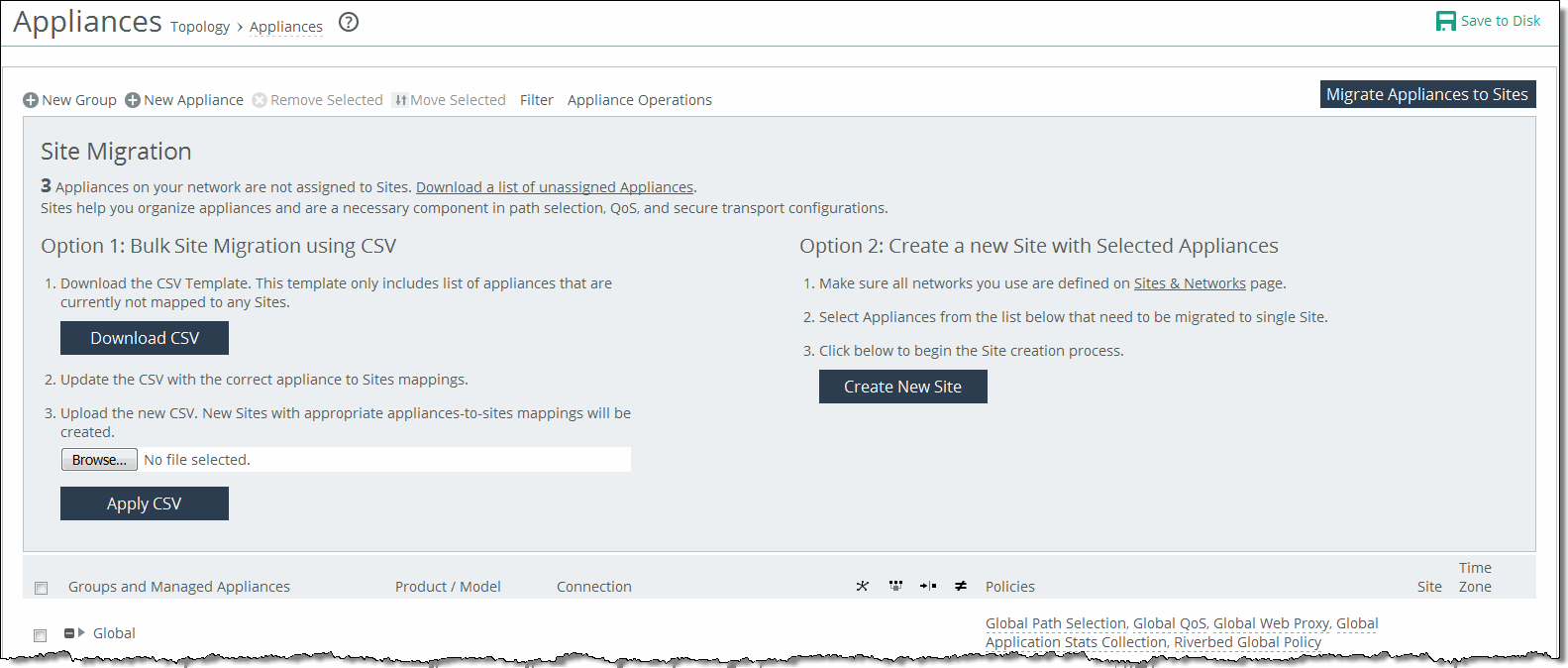
You can migrate appliances to sites under Manage > Topology: Appliances. Click Migrate Appliances to Sites to display the Site Migration page.
Migrating appliances to sites
Click Download CSV to download the CSV template and open it in Excel.
Define the sites. The Site Name, Site Type, Site Region, Subnets, and Peers (if custom endpoints configured) are required. The Site Name column doesn’t accept commas. We recommend creating the region and type before you populate this CSV template.
Object type
(i.e., site; required) | Site name (required) Don’t use commas. | Site type (required) | Site region (required) | Subnets (comma-separated list) | Connectivity template | Uplink1 gateway |
|---|
Site | Sacramento CA | Branch | USA | 10.0.1.0/24, 10.0.2.0/24 | Optional | Optional |
Site | San Francisco CA | Branch | USA | 10.0.3.0/24, 10.0.4.0/24 | Optional | Optional |
Uplink Gateway fields are ignored unless a connectivity template is specified. If one is specified, then Uplink Gateway is required. Internet traffic can be either Direct-to-Net or backhauled through a site. Specify a site to backhaul through or leave blank for Direct-to-Net.
Associate appliances to sites. The Object Type, Serial Number, and Site Name are required. The Site Name doesn’t accept commas. You can also assign the appliance to an already existing site: for example, existing sites.
Object type
(i.e., appliance; required) | Serial number (required) | Hostname | IP address | Site name
(required) Don’t use commas. |
|---|
SteelHead | C48YG0000490F | Pacific | 10.0.1.0/24 | Sacramento CA |
SteelHead EX | C48WN000099B | Atlantic | 10.0.1.2/24 | New York New York |
Close and save the CSV file. On the Appliances page under Option 1, click Browse to navigate to the CSV template. Click Apply CSV to upload the new CSV template to the SCC. New sites with appropriate appliances to sites mappings are created and displayed in the Appliance/Group table.
Creating new sites from selected appliances
You can create new sites under Manage > Topology: Appliances. Select the appliances you want to migrate, and click Migrate Appliances to Sites to display the Site Migration panel.
Select the appliances in the Appliance/Group table to be migrated to single site. Under Option 2, click Create New Site to expand the page and display the controls to create a site. Under Riverbed Appliances, the selected appliances automatically appear. Complete the configuration.
About appliance groups
All groups are based on a nested hierarchy. Appliance groups allow you to assign policies to appliances in that group. Global group policies can be overridden by policies lower in the hierarchy. The hierarchical management of devices allows access to all of the Riverbed appliances and in a global infrastructure.
You should carefully design your network hierarchy so that you can identify what policies are needed on the appliances in each group. Carefully designing the group hierarchy will ensure that you implement the best solution for your network.
All groups are based on a nested hierarchy. Appliance groups allow you to assign policies to appliances in that group. Global group policies can be overridden by policies lower in the hierarchy. The hierarchical management of devices allows access to all of the Riverbed appliances in a global infrastructure.
Configuring appliance groups
You can configure appliance groups under Manage > Topology: Appliance. Click New Group to expand the page. These configuration options are available:
Name
Specifies the name for the group.
Parent Group
Specifies the parent group from the drop-down list. The default value is Global.
Comment
Provides a description to help you identify the group.
Add
Adds the group to the Appliance/Group table. The SCC redisplays the table and applies your changes to the running configuration, which is stored in memory.
Editing appliance groups
You can edit appliance groups under Manage > Topology: Appliances. In the Appliances table, click the group name to expand the page. Click Edit Group to modify the parent group and comments. Select the parent group from the drop-down list, and type a comment to help you identify the group in the Comment text box.
Adding policies to appliance groups
You can add policies to appliance groups under Manage > Topology: Appliances. Click the group name to expand the page, and click Policies to expand the page. Click Add/Remove Policies to display the pop-up window, and select the policy you want to add. A message is displayed stating the policy has been added. To remove the policy, click Revert.
The policy is displayed in the Policy Pages table. The SCC redisplays the table and applies your changes to the running configuration, which is stored in memory. Click Done to return to the Appliance/Group table.