Configuring Network Integration Features
This chapter describes how to configure advanced features such as asymmetric routing, connection forwarding, encryption, flow export, joining a Windows domain, simplified routing, and WCCP.
This chapter includes these topics:
Configuring asymmetric routing features
Configuring connection forwarding features
Configuring IPSec encryption
Configuring subnet side rules
Configuring flow statistics
Joining a Windows domain or workgroup
Configuring simplified routing features
Configuring WCCP
Configuring hardware-assist rules
For details about basic and advanced deployment types, see the SteelHead Deployment Guide.
Configuring asymmetric routing features
You enable asymmetric route detection in the Networking > Networking Integration: Asymmetric Routing page.
Asymmetric route detection automatically detects and reports asymmetric routing conditions and caches this information to avoid losing connectivity between a client and a server.
Asymmetric routing is when a packet takes one path to the destination and takes another path when returning to the source. Asymmetric routing is common within most networks; the larger the network, the more likely there is asymmetric routing in the network.
The asymmetric routing feature is compatible with IPv6.
Asymmetric routing is undesirable for many network devices including, firewalls, VPNs, and RiOS appliances. These devices all rely on seeing every packet to function properly. When RiOS appliances are deployed in a network, all TCP traffic must flow through the same appliances in the forward and reverse directions. If traffic flows through a RiOS appliance in one direction and not the other, then TCP clients are unable to make connections to TCP servers. When deploying RiOS appliances into redundant networks, there is a possibility of traffic taking different forward and return paths so that traffic in one direction goes through RiOS appliances but traffic in the reverse direction does not.
Asymmetric automatic detection enables RiOS appliances to detect the presence of asymmetry within the network. Asymmetry is detected by the client-side appliances. Once detected, the appliance passes through asymmetric traffic unoptimized allowing the TCP connections to continue to work. The first TCP connection for a pair of addresses might be dropped because during the detection process the appliances have no way of knowing that the connection is asymmetric.
If asymmetric routing is detected, an entry is placed in the asymmetric routing table and any subsequent connections from that IP-address pair is passed through unoptimized. Further connections between these hosts are not optimized until that particular asymmetric routing cache entry times out.
The Networking > Network Integration: Asymmetric Routing page displays the asymmetric routing table. This table describes the different types of asymmetry.
 
Type
Description
Asymmetric routing table and log entries
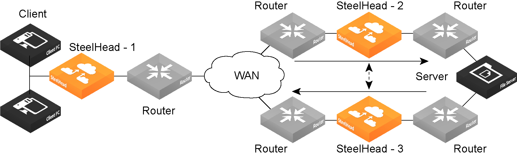
Complete Asymmetry
Packets traverse both RiOS appliances going from the client to the server but bypass both appliances on the return path.
Asymmetric Routing Table: bad RST
Log: Sep 5 11:16:38 gen-sh102 kernel: [intercept.WARN] asymmetric routing between 10.11.111.19 and 10.11.25.23 detected (bad RST)
Server-Side Asymmetry
Packets traverse both RiOS appliances going from the client to the server but bypass the server-side SteelHead on the return path.
Asymmetric Routing Table: bad SYN/ACK
Log: Sep 7 16:17:25 gen-sh102 kernel: [intercept.WARN] asymmetric routing between 10.11.25.23:5001 and 10.11.111.19:33261 detected (bad SYN/ACK)
Client-Side Asymmetry
Packets traverse both RiOS appliances going from the client to the server but bypass the client-side appliance on the return path.
Asymmetric Routing Table: no SYN/ACK
Log: Sep 7 16:41:45 gen-sh102 kernel: [intercept.WARN] asymmetric routing between 10.11.111.19:33262 and 10.11.25.23:5001 detected (no SYN/ACK)
multiSYN Retransmit
The types of multi-SYN retransmits are:
Probe-filtered occurs when the client-side appliance sends out multiple SYN+ frames and does not get a response.
SYN-remit occurs when the client-side appliance receives multiple SYN retransmits from a client and does not see a SYN/ACK packet from the destination server.
Asymmetric Routing Table: probe-filtered (not-AR)
Log: Sep 13 20:59:16 gen-sh102 kernel: [intercept.WARN] it appears as though probes from 10.11.111.19 to 10.11.25.23 are being filtered. Passing through connections between these two hosts.
Detecting and caching asymmetric routes does not optimize these packets. If you want to optimize asymmetric routed packets, you must make sure that packets going to the WAN always go through a RiOS appliance either by using a multiport SteelHead, connection forwarding, or using external ways to redirect packets, such as WCCP or PBR.
For details, see Configuring connection forwarding features or the SteelHead Deployment Guide.
Troubleshooting asymmetric routes
You can use these tools to detect and analyze asymmetric routes:
TCP Dump - Run a TCP dump diagnostic report on the client-side appliance to verify the packet sequence that is causing the asymmetric route detection. You can take traces on the LAN and WAN ports of the appliance and, based on the packet maps, look for the packet sequence that is expected for the type of warning message that was in the log.
As an example, perform these steps to obtain information about all packets on the WAN interface sourced from or destined to 10.0.0.1, and with a source and destination TCP port of 80:
1. Choose Reports > Diagnostics: TCP Dumps to display the TCP Dumps page.
2. Click Add a New TCP Dump.
3. Select the WAN interface.
4. Specify 10.0.0.1 as the source and destination address.
5. Specify TCP port 80 as the source and destination port.
6. Select the Schedule Dump check box and specify the date and time to initiate the dump.
7. Specify any other options such as the capture filename or duration.
8. Click Add.
For details, see Capturing and uploading TCP dump files.
Trace Route - From the CLI, run the traceroute command to discover what path a packet is taking from the client to the server and from the server to the client. You access the client and run the traceroute command with the IP address of the server, and then run the traceroute command from the server with the IP address of the client. For example, for a Cisco router with a client address of 10.1.0.2 and a server address of 10.0.0.4:
client# traceroute 10.0.0.4 Type escape sequence to abort.
Tracing the route to 10.0.0.4
1 10.1.0.1 4 msec 0 msec 4 msec
2 10.0.0.2 4 msec 4 msec 0 msec
3 10.0.0.3 4 msec 4 msec 0 msec
4 10.0.0.4 4 msec 4 msec 0 msec
server# traceroute 10.1.0.2 Type escape sequence to abort.
Tracing the route to 10.1.0.2
1 10.0.0.6 4 msec 0 msec 4 msec
2 10.0.0.5 4 msec 4 msec 0 msec
3 10.1.0.1 4 msec 4 msec 0 msec
4 10.1.0.2 4 msec 4 msec 0 msec
For details, see the Riverbed Command-Line Interface Reference Manual or the SteelHead Deployment Guide.
To automatically detect asymmetric routing
1. Choose Networking > Network Integration: Asymmetric Routing to display the Asymmetric Routing page.
Asymmetric Routing page
2. Under Asymmetric Routing Settings, complete the configuration as described in this table.
Control
Description
Enable Asymmetric Routing Detection
Detects asymmetric routes in your network.
Enable Asymmetric Routing Pass-Through
Enables pass-through traffic if asymmetric routing is detected.
If asymmetric routing is detected, the pair of IP addresses, defined by the client and server addresses of this connection, is cached on the SteelHead. Further connections between these hosts are passed through unoptimized until that particular asymmetric routing cache entry times out.
Detecting and caching asymmetric routes doesn’t optimize these packets. If you want to optimize asymmetric routed packets you must make sure that the packets going to the WAN always go through a SteelHead either by using a multiport SteelHead, connection forwarding, or using external ways to redirect packets, such as WCCP or PBR.
For details, see the SteelHead Deployment Guide.
Remove Selected
Select the check box next to the name and click Remove Selected.
3. Click Save to save your settings permanently.
Related topics
Configuring connection forwarding features
Generating system dumps
Viewing process dumps
Configuring connection forwarding features
You configure connection forwarding for a network with multiple paths from the server in the Networking > Network Integration: Connection Forwarding page.
The AWS SteelHead-c does not support connection forwarding; however, the ESX SteelHead-c supports it.
You enable connection forwarding only in asymmetric networks. An asymmetric network is a network in which a client request traverses a different network path than the server response. The default port for connection forwarding is 7850.
For virtual in-path deployments with multiple RiOS appliances, including WCCP clusters and connection forwarding, you must always allow in-path neighbor failure. Allowing in-path neighbor failure is necessary because certain events, such as network failures, and router or SteelHead cluster changes, can cause routers to change the destination appliance for TCP connection packets. When this happens, appliances must be able to redirect traffic to each other to ensure that optimization continues.
To optimize connections in asymmetric networks, packets traveling in both directions must pass through the same client-side appliance and server-side SteelHead. If you have one path from the client to the server and a different path from the server to the client, you must enable in-path connection forwarding and configure the appliances to communicate with each other. These appliances are called neighbors and exchange connection information to redirect packets to each other.
When RiOS determines an IPv6 incompatibility between connection-forwarding neighbors, it triggers an alarm indicating that a peer appliance is incompatible. For details, see Configuring alarm settings and Viewing virtualization datastore reports.
You must enable connection forwarding in a WCCP cluster. With connection forwarding enabled, the WCCP load balancing algorithm considers the total number of in-path interfaces of all neighbors in the service group when balancing the load across the interfaces. If you do not enable connection forwarding, the appliance with the lowest IP address assigns all traffic flows to itself. For details, see the SteelHead Deployment Guide.
When using connection forwarding in a WCCP cluster with IPv6, we recommend upgrading all appliances in the cluster to RiOS 8.5 or later. You must also enable multiple interface support.
Asymmetric network
You can place neighbors in the same physical site or in different sites, but the latency between them must be small because the packets traveling between them are not optimized.
When you define a neighbor, you specify the appliance in-path IP address, not the primary IP address.
If there are more than two possible paths, additional appliances must be installed on each path and configured as neighbors. Neighbors are notified in parallel so that the delay introduced at the connection setup is equal to the time it takes to get an acknowledgment from the furthest neighbor.
Connection-forwarding neighbors must use the same WAN visibility mode. For details, see Configuring in-path rules.
For details about connection forwarding, see the SteelHead Deployment Guide.
To enable connection forwarding
1. Choose Networking > Network Integration: Connection Forwarding to display the Connection Forwarding page.
Connection Forwarding page
2. Under Connection Forwarding Settings, complete the configuration as described in this table.
Control
Description
Enable Connection Forwarding
Enables connection forwarding by default on all neighbors added to the peer list. The default value is 7850.
Port
Specify the port number to use as the default for the neighbor appliance in-path port. The default value is 7850.
Keep-Alive Interval
Specify the number of seconds to use as the default interval for ping commands between neighbor appliances. The default value is 1.
Keep-Alive Count
Specify the number of tries to use as the default number of failed ping attempts before an appliance terminates a connection with a neighbor. The default value is 3.
In-Path Neighbor Failure
Uses the neighbor appliance to optimize new connections if the appliance fails.
For in-path deployments that use connection forwarding with WCCP, enabling this option ensures that if one appliance fails, the neighbor appliance continues to optimize new connections.
For in-path deployments that use connection forwarding without WCCP, enabling this option ensures that an appliance attempts to optimize new connections that are symmetrically routed, even after all of the neighbor appliances on another network path failed. New asymmetrically routed connections are not optimized but passed through.
Multiple Interface Support
Enables high availability on appliances configured with multiple in-path interfaces and using connection forwarding with another multiport SteelHead. This option makes all neighbor in-path interface IP addresses visible to each peer to ensure proper neighbor communication if the in-path0_0 interface fails.
RiOS 6.5 and later require connection forwarding in a WCCP cluster.
You must enable multiple interface support for a connection-forwarding neighbor to work with IPv6.
3. Click Apply to apply your settings.
4. Click Save to save your settings permanently.
To add a new neighbor
1. Under Neighbor Table, complete the configuration as described in this table.
 
Control
Description
Add a New Neighbor
Displays the controls to add a new neighbor.
Hostname
Specify a hostname.
In-Path IP Address
Specify the in-path IP address for the neighbor appliance. When you define a neighbor, you must specify the appliance in-path IP address, not the primary IP address.
You can use connection forwarding with IPv6 addresses if the following conditions are met:
Both appliances must be running RiOS 9.6 or later.
Multiple interface support must be selected.
The IPv6 Connection Forwarding check box must be selected in the Connection Forwarding Settings area of this page.
Port
Specify the in-path port for the neighbor appliance. The default port is 7850.
Additional IP Addresses
Adds a neighbor appliance to the neighbor list.
Add
Adds a new neighbor.
Remove Selected
Select the check box next to the name and click Remove Selected.
2. Click Apply to apply your settings.
3. Click Save to save your settings permanently.
To modify the neighbor properties, select the IP address of the neighbor and complete the configuration.
Related topics
Configuring general service settings
Configuring asymmetric routing features
Configuring IPSec encryption
You configure IPSec encryption to allow data to be communicated securely between peer appliances in the Optimization > SSL: Secure Peering (IPSEC) page.
Enabling IPSec encryption makes it difficult for a third party to view your data or pose as a computer you expect to receive data from. To enable IPSec, you must specify at least one encryption and authentication algorithm. Only optimized data is protected, pass-through traffic is not.
Enabling IPSec support is optional.
RiOS does not support IPSec over IPv6.
In RiOS 9.0, IPSec secure peering and the secure transport service are mutually exclusive. The secure transport service is enabled by default. Before you enable IPSec secure peering, you must disable the secure transport service.
RiOS provides support for SSL peering beyond traditional HTTPS traffic. For details, see Configuring secure peers.
You must set IPSec support on each peer appliance in your network for which you want to establish a secure connection. You must also specify a shared secret on each peer appliance.
If you NAT traffic between appliances, you cannot use the IPSec channel between the appliances because the NAT changes the packet headers, causing IPSec to reject them.
To enable IPSec encryption
1. Choose Optimization > SSL: Secure Peering IPsec to display the Secure Peering (IPSEC) page.
Secure Peering (IPSEC) page
2. Under General Settings, complete the configuration as described in this table.
Control
Description
Enable Authentication and Encryption
Enables authentication between SteelHeads. By default, this option is disabled.
Enable Perfect Forward Secrecy
Enables additional security by renegotiating keys at specified intervals. If one key is compromised, subsequent keys are secure because they’re not derived from previous keys. By default, this option is enabled.
Encryption Policy
Select one of these encryption methods from the drop-down list:
DES - Encrypts data using the Data Encryption Standard algorithm. DES is the default value.
NULL - Specifies the null encryption algorithm.
None - Doesn’t apply an encryption policy.
3DES - Appears when a valid Enhanced Cryptography License Key is installed on the appliance. Encrypts data using the Triple Digital Encryption Standard with a 168-bit key length. This standard is supported for environments where AES has not been approved, but is both slower and less secure than AES.
AES - Appears when a valid Enhanced Cryptography License Key is installed on the appliance. Encrypts data using the Advanced Encryption Standard (AES) cryptographic key length of 128 bits.
AES256 - Appears when a valid Enhanced Cryptography License Key is installed. Encrypts data using the Advanced Encryption Standard (AES) cryptographic key length of 256 bits. Provides the highest security.
Optionally, select an algorithm from the method 2, 3, 4, or 5 drop-down lists to create a prioritized list of encryption policies for negotiating between peers.
Note: Peer SteelHeads must both have a valid Enhanced Cryptography License Key installed to use 3DES, AES, or AES256. When a SteelHead has the valid Enhanced Cryptography License Key installed and an IPSec encryption level is set to 3DES or AES, and a peer SteelHead doesn’t have a valid Enhanced Cryptography License Key installed, the appliances uses the highest encryption level set on the appliance without the key.
Authentication Policy
Select one of these authentication methods from the drop-down list:
MD5 - Specifies the Message-Digest 5 algorithm, a widely used cryptographic hash function with a 128-bit hash value. This is the default value.
SHA-1 - Specifies the Secure Hash Algorithm, a set of related cryptographic hash functions. SHA-1 is considered to be the successor to MD5.
Optionally, select an algorithm from the method 2 drop-down list to create a secondary policy for negotiating the authentication method to use between peers. If the first authentication policy negotiation fails, the peer SteelHeads use the secondary policy to negotiate authentication.
Time Between Key Renegotiations
Specify the number of minutes between quick-mode renegotiation of keys using the Internet Key Exchange (IKE) protocol. IKE uses public key cryptography to provide the secure transmission of a secret key to a recipient so that the encrypted data can be decrypted at the other end. The default value is 240 minutes.
Enter the Shared Secret/Confirm the Shared Secret
Specify and confirm the shared secret. All the SteelHeads in a network for which you want to use IPSec must have the same shared secret.
Add a New Secure Peer
Displays the controls to add a new secure peer.
Peer IP Address - Specify the IP address for the peer SteelHead (in-path interface) for which you want to make a secure connection.
Add
Adds the peer specified in the Peer IP Address text box.
If a connection has not been established between the two SteelHeads that are configured to use IPSec security, the peers list doesn’t display the peer SteelHead status as mature.
Note: Adding a peer causes a short service disruption (3 to 4 seconds) to the peer that is configured to use IPSec security.
Remove Selected
Select the check box next to the name and click Remove Selected.
3. Click Save to save your settings permanently.
4. If you have changed an IPSec encryption setting, you must restart the optimization service. For details, see Starting and stopping the optimization service.
The peered appliances do not establish the IPSec channel until they are optimizing traffic.
About the secure peers list
The Secure Peers list displays the peers with the encryption and authentication policies and one of these states:
Mature - The IPSec connection is established and usable.
Larval - The IPSec connection is being established.
Disconnected - The IPSec connection is not yet established or is not usable.
Configuring subnet side rules
You configure subnet side rules in the Configure > Networking > Subnet Side Rules page.
Subnet side rules enable you to specify subnets as LAN-side subnets or WAN-side subnets for a virtual in-path appliance. Subnet side rules instruct the appliance to identify traffic as originating from the WAN side of the appliance or the LAN side of the appliance based on the source subnet. You must configure subnets on each appliance in a virtual in-path configuration, because the subnets for each will likely be unique.
For appliances configured for virtual in-path deployment (for Layer-4 switch, PBR, WCCP, and SteelHead Interceptor), you must configure subnet side rules to support client-side appliances or for appliances that support flow export collectors such as NetFlow. You must configure subnets on each appliance in a virtual in-path configuration, because the subnets for each will likely be unique.
If you configure a client-side appliance for virtual in-path deployment, you must configure subnet side rules to identify LAN-side traffic, otherwise the appliance does not optimize traffic from client-side connections. In virtual in-path configurations, all traffic flows in and out of one physical interface, and the default subnet side rule causes all traffic to appear to originate from the WAN side of the device.
Because VSP is enabled by default on SteelFusion Edges, and the default subnet rule assumes that all traffic is coming from the WAN, the default rule prevents client-side connections from being optimized until you create a rule to identify traffic that should be treated as LAN-side traffic. The position of this rule must be at the start of the list of rules, above the default rule.
If you configure a virtual in-path appliance to use flow export collectors such as NetFlow, you can analyze nonoptimized traffic or passed-through traffic correctly. If you do not configure subnet side rules, the appliance cannot discern whether the traffic is traveling from the LAN to the WAN or in the opposite direction. This can result in over-reporting traffic in a particular direction or for a particular interface.
FakeIndex is necessary for correct optimized traffic reporting. For details, see the SteelHead Deployment Guide.
To add subnet side rules
1. Choose Networking > Network Services: Subnet Side Rules to display the Subnet Side Rules page.
Subnet Side Rules page
2. Complete the configuration as described in this table.
Control
Description
Add a Subnet Side Rule
Displays the controls to create a subnet side rule.
Insert Rule At
Select Start, End, or a rule number from the drop-down list.
SteelHeads evaluate rules in numerical order starting with rule 1. If the conditions set in the rule match, then the rule is applied, and the system moves on to the next packet. If the conditions set in the rule do not match, the system consults the next rule. For example, if the conditions of rule 1 do not match, rule 2 is consulted. If rule 2 matches the conditions, it is applied, and no further rules are consulted.
Subnet
Specify the subnet. The subnet can be either an IPv4 or an IPv6 address. Use the following format:
<ip address>/<subnet mask>
xxx.xxx.xxx.xxx/xx (IPv4)
x:x:x:x/xxx (IPv6)
Subnet is on the LAN side of this appliance
In virtual in-path configurations, all traffic is flowing in and out of one physical interface. Select to specify that the subnet is on the LAN side of the device.
Subnet is on the WAN side of this appliance
In virtual in-path configurations, all traffic is flowing in and out of one physical interface. Select to specify that the subnet is on the WAN side of the device.
Add
Adds the rule to the subnet map table. The Management Console redisplays the subnet map table and applies your changes to the running configuration, which is stored in memory.
Remove Subnet Rules
Select the check box next to the name and click Remove Subnet Rules.
Move Subnet Rules
Moves the selected rules. Click the arrow next to the desired rule position; the rule moves to the new position.
You cannot delete the default rule that optimizes all remaining WAN-side traffic that has not been selected by another rule. This rule is always listed last.
Related topics
Configuring flow statistics
You enable and configure flow statistic settings in the Networking > Network Services: Flow Statistics page. You can also enable flow export to an external collector and to a CascadeFlow collector. CascadeFlow collectors can aggregate information about QoS configuration and other application statistics to send to a SteelCentral NetProfiler. The Enterprise NetProfiler summarizes and displays the QoS configuration statistics.
By default, flow export is disabled.
You cannot export data flowing through a secure transport tunnel to a flow collector. Secure transport provides security by creating tunnels between the peers through which the traffic flows. IPSec is used to provide authentication and encryption to the packets that flow through the tunnels. Specifically, secure transport uses the ESP mode of IPSec. Flow statistic collectors cannot collect ESP packet data flow information.
External collectors use information about network data flows to report trends such as the top users, peak usage times, traffic accounting, security, and traffic routing. You can export preoptimization and post-optimization data to an external collector.
The Top Talkers feature enables a report that details the hosts, applications, and host and application pairs that are either sending or receiving the most data on the network. The Top Talkers report does not use a NetFlow Collector.
Enabling flow export
SteelFusion Edge supports NetFlow 5, NetFlow 9, and CascadeFlow and CascadeFlow-compatible versions. Flow export requires these components:
Exporter - When you enable flow export support, the appliance exports data about the individual flows that it sees as they traverse the network.
Collector - A server or appliance designed to aggregate data sent to it by the appliance and other exporters.
Analyzer - A collection of tools used to analyze the data and provide relevant data summaries and graphs. NetFlow analyzers are available for free or from commercial sources. Analyzers are often provided in conjunction with the collectors.
Before you enable flow export in your network, consider these points:
Flow data typically consumes less than 1 percent of link bandwidth. With low-bandwidth links, ensure that flow export does not consume too much bandwidth, thereby impacting application performance.
You can reduce the amount of bandwidth consumption by applying filters that only export the most critical information needed for your reports.
Flow export in virtual in-path deployments
In virtual in-path deployments, such as WCCP or PBR, traffic arrives and leaves from the same WAN interface. When the Edge exports data to a flow export collector, all traffic has the WAN interface index. This behavior is correct because the input interface is the same as the output interface.
For details about configuring flow export in a virtual in-path deployment, see Configuring subnet side rules.
To distinguish between LAN-to-WAN and WAN-to-LAN traffic in virtual in-path deployments, see the SteelHead Deployment Guide.
To enable flow statistic settings
1. Choose Networking > Network Services: Flow Statistics to display the Flow Statistics page.
Flow Statistics page
2. Under Flow Statistics Settings, complete the configuration as described in this table.
Control
Description
Enable Application Visibility
Continuously collects detailed application-level statistics for both pass-through and optimized traffic. The Application Visibility and Application Statistics reports display these statistics. This statistic collection is disabled by default.
To view the reports, choose Reports > Networking: Application Statistics or Application Visibility.
Enable WAN Throughput Statistics
Continuously collects WAN throughput statistics, which the WAN Throughput report displays. This statistic collection is enabled by default; however, you can disable the collection to save processing power.
To view the WAN throughput statistics, choose Reports > Networking: WAN Throughput.
Enable Top Talkers
Continuously collects statistics for the most active traffic flows. A traffic flow consists of data sent and received from a single source IP address and port number to a single destination IP address and port number over the same protocol.
The most active, heaviest users of WAN bandwidth are called the Top Talkers. A flow collector identifies the top consumers of the available WAN capacity (the top 50 by default) and displays them in the Top Talkers report. Collecting statistics on the Top Talkers provides visibility into WAN traffic without applying an in-path rule to enable a WAN visibility mode.
You can analyze the Top Talkers for accounting, security, troubleshooting, and capacity planning purposes. You can also export the complete list in CSV format.
The collector gathers statistics on the Top Talkers based on the proportion of WAN bandwidth consumed by the top hosts, applications, and host and application pair conversations. The statistics track pass-through or optimized traffic, or both. Data includes TCP or UDP traffic, or both (configurable in the Top Talkers report page).
A NetFlow collector is not required for this feature.
Optionally, select a time period to adjust the collection interval:
24-hour Report Period - For a five-minute granularity (the default setting).
48-hour Report Period - For a ten-minute granularity.
The system also uses the time period to collect SNMP Top Talker statistics. For top talkers displayed in the Top Talker report and SNMP Top Talker statistics, the system updates the Top Talker data ranks either every 300 seconds (for a 24- hour reporting period), or 600 seconds (for a 48-hour reporting period).
The system saves a maximum of 300 Top Talker data snapshots, and aggregates these to calculate the top talkers for the 24-hour or 48-hour reporting period.
The system never clears top talker data at the time of polling; however, every 300 or 600 seconds, it replaces the oldest Top Talker data snapshot of the 300 with the new data snapshot.
After you change the reporting period, it takes the system one day to update the Top Talker rankings to reflect the new reporting period. In the interim, the data used to calculate the Top Talkers still includes data snapshots from the original reporting period. This delay applies to Top Talker report queries and SNMP Top Talker statistics.
3. Click Apply to apply your settings.
4. Click Save to save your settings permanently.
To enable flow export settings
1. Choose Networking > Network Services: Flow Statistics to display the Flow Statistics page.
2. Under Flow Export Settings, complete the configuration as described in this table.
3. Click Apply to apply your settings.
Control
Description
Enable Flow Export
Enables the Edge to export network statistics about the individual flows that it sees as they traverse the network. By default, this setting is disabled.
Export QoS and Application Statistics to CascadeFlow Collectors
Sends application-level statistics from all sites to a SteelCentral collector on a SteelCentral appliance. SteelCentral appliances provide central reporting capabilities. The collector aggregates QoS and application statistics to provide visibility using detailed records specific to flows traversing the SteelHead.
The appliance sends SteelCentral an enhanced version of NetFlow called CascadeFlow. CascadeFlow includes:
NetFlow v9 extensions for round-trip time measurements that enable you to understand volumes of traffic across your WAN and end-to-end response time.
extensions that enable a SteelCentral NetExpress to properly measure and report on the benefits of optimization.
After the statistics are aggregated on a Cascade appliance, you can use its central reporting capabilities to:
analyze overall WAN use, such as traffic generated by application, most active sites, and so on.
troubleshoot a particular application by viewing how much bandwidth it received, checking for any retransmissions, interference from other applications, and so on.
compare actual application use against your outbound QoS policy configuration to analyze whether your policies are effective. For example, if your QoS policy determines that Citrix should get a minimum of 10 percent of the link, and the application statistics reveal that Citrix performance is unreliable and always stuck at 10 percent, you might want to increase that minimum guarantee.
You must enable outbound QoS on the appliance, add a CascadeFlow collector, and enable REST API access before sending QoS configuration statistics to a SteelCentral NetProfiler.
To enable QoS, choose Networking > Network Services: Outbound QoS. You cannot export statistics for inbound QoS.
The collectors appear in the Flow Collector list at the bottom of the Configure > Networking: Flow Statistics page.
 
To enable REST API access, choose Administration > Security: REST API Access.
The CascadeFlow collector collects read-only statistics on both pass-through and optimized traffic. When you use CascadeFlow, the appliance sends four flow records for each optimized TCP session: ingress and egress for the inner-channel connection, and ingress and egress for the outer-channel connection. A pass-through connection still sends four flow records, even though there are no separate inner- and outer-channel connections. In either case, the SteelCentral NetExpress merges these flow records together with flow data collected for the same flow from other devices.
For details, see the SteelCentral Network Performance Management Deployment Guide.
Enable IPv6
Enables support for IPv6 addresses for flow exports.
Active Flow Timeout
Optionally, specify the amount of time, in seconds, the collector retains the list of active traffic flows. The default value is 1800.
You can set the time-out period even if the Top Talkers option is enabled.
Inactive Flow Timeout
Optionally, specify the amount of time, in seconds, the collector retains the list of inactive traffic flows. The default value is 15.
4. Click Save to save your settings permanently.
Related topics
Configuring subnet side rules
Viewing top talkers reports
Viewing application statistics reports
To add a Flow collector
1. Under Flow Collectors, complete the configuration as described in this table.
Control
Description
Add a New Flow Collector
Displays the controls to add a Flow collector.
Collector IP Address
Specify the IP address for the Flow collector.
Port
Specify the UDP port the Flow collector is listening on. The default value is 2055.
Version
Select one of these versions from the drop-down list:
CascadeFlow - Use with Cascade Profiler 8.4 or later.
CascadeFlow-compatible - Use with Cascade Profiler 8.3.2 or earlier, and select the LAN Address check box.
NetFlow v9 - Enables both ingress and egress flow records.
NetFlow v5 - Enables ingress flow records.
For details on using NetFlow records with Cascade, see the SteelCentral Network Performance Management Deployment Guide.
CascadeFlow and CascadeFlow-compatible are enhanced versions of flow export to the SteelCentral. These versions allow automatic discovery and interface grouping for SteelHeads in a Riverbed SteelCentral NetProfiler or a SteelCentral Flow Gateway and support WAN and optimization reports in SteelCentral. For details, see the SteelCentral NetProfiler and NetExpress User’s Guide and the SteelCentral Flow Gateway User’s Guide.
Packet Source Interface
Select the interface to use as the source IP address of the flow packets (Primary, Aux, or MIP) from the drop-down list. NetFlow records sent from the SteelHead appear to be sent from the IP address of the selected interface.
LAN Address
Causes the TCP/IP addresses and ports reported for optimized flows to contain the original client and server IP addresses and not those of the SteelHead. The default setting displays the IP addresses of the original client and server without the IP address of the SteelHeads.
This setting is unavailable with NetFlow v9, because the optimized flows are always sent out with both the original client server IP addresses and the IP addresses used by the SteelHead.
Capture Interface/Type
Specify the traffic type to export to the flow collector. Select one of these types from the drop-down list:
All - Exports both optimized and nonoptimized traffic.
Optimized - Exports optimized traffic.
Optimized - Exports optimized LAN or WAN traffic when WCCP is enabled.
Passthrough - Exports pass-through traffic.
None - Disables traffic flow export.
The default is All for LAN and WAN interfaces, for all four collectors. The default for the other interfaces (Primary, rios_lan, and rios_wan) is None. You can’t select a MIP interface.
Enable Filter
(CascadeFlow and NetFlow v9 only) Filter flow reports by IP and subnets or IP:ports included in the Filter list. When disabled, reports include all IP addresses and subnets.
Filter
(CascadeFlow and NetFlow v9 only) Specify the IP and subnet or IP:port to include in the report, one entry per line, up to 25 filters maximum. This field supports both IPv4 and IPv6 subnets.
Add
Adds the collector to the Collector list.
Remove Selected
Select the check box next to the name and click Remove Selected.
2. Click Apply to apply your settings.
3. Click Save to save your settings permanently.
Troubleshooting
To troubleshoot your flow export settings:
Make sure the port configuration matches on the RiOS appliance and the listening port of the collector.
Ensure that you can reach the collector from the appliance (for example, –i aux 1.1.1.1 where 1.1.1.1 is the NetFlow collector and aux is the Packet Source Interface).
Verify that your capture settings are on the correct interface and that traffic is flowing through it.
Joining a Windows domain or workgroup
A server-side SteelHead can join a Windows domain or workgroup in the Optimization > Active Directory: Domain Join page. This page provides a central place for a SteelHead to join a Windows domain or workgroup.
The SteelHead can join a single Windows domain to use these features:
SMB signing trust for CIFS optimizations. For details, see Configuring SMB signing.
MAPI 2007 encrypted traffic optimization authentication. For details, see Configuring MAPI optimization.
MAPI Exchange as a hosted service using Active Directory integrated mode for Windows 2003 and 2008 or later.
RiOS includes an automatic way to join the domain and deploy the server-side SteelHead in Active Directory integrated mode for Windows 2003 and 2008. For details, see Configuring domain authentication automatically.
Domain and local workgroup settings
You can choose between two user authentication modes: domain or local workgroup. Creating a local workgroup eliminates the need to join a Windows domain and simplifies the configuration process, but a workgroup does not support SMB signing, MAPI 2007 encrypted traffic optimization authentication, or MAPI Exchange as a hosted service.
You can join a SteelHead to a domain in Active Directory 2008 integrated mode without administrator privileges. For details, see the Riverbed Knowledge Base article How to Join SteelHead to Domain as a RODC or BDC without Administrator privileges at https://supportkb.riverbed.com/support/index?page=content&id=S18097&actp.
Domain mode
In Domain mode, you configure the SteelHead to join a Windows domain (typically, the domain of your company). When you configure the SteelHead to join a Windows domain, you do not have to manage local accounts in the branch office, as you do in Local Workgroup mode.
Domain mode allows a domain controller (DC) to authenticate users accessing its file shares. The DC can be located at the remote site or over the WAN at the main data center. The SteelHead must be configured as a Member Server or Active Directory integrated in the Windows 2000 or later Active Directory Services (ADS) domain. Domain users are allowed to use the Kerberos delegation trust facility and NTLM environments for MAPI 2007 encryption or SMB signing based on the access permission settings provided for each user.
In RiOS 9.0, the support for one-way trusts includes Windows 7 clients without requiring a registry change on the Windows 7 client. You must join the server-side SteelHead to the domain using the Active Directory integrated (Windows 2003/2008) mode. This mode allows the SteelHead to use authentication within the Active Directory environment on the Exchange servers that provide Microsoft Exchange online services. The domain that the server-side SteelHead joins must be either the same as the client user or any domain that trusts the domain of the client user.
Before enabling domain mode make sure that you:
configure the DNS server correctly. The configured DNS server must be the same DNS server to which all the Windows client computers point. To use SMB signing, the server-side SteelHead must be in DNS. For details, see To specify DNS settings.
have a fully qualified domain name. This domain name must be the domain name for which all the Windows desktop computers are configured.
Local Workgroup mode
In Local Workgroup mode, you define a workgroup and add individual users that have access to the SteelHead. The SteelHead does not join a Windows domain.
Use Local Workgroup mode in environments where you do not want the SteelHead to be a part of a Windows domain. Creating a workgroup eliminates the need to join a Windows domain and simplifies the configuration process.
If you use Local Workgroup mode you must manage the accounts and permissions for the branch office on the SteelHead. The Local Workgroup account permissions might not match the permissions on the origin-file server.
To configure a Windows domain in Local Workgroup mode
1. Select Optimization > Active Directory: Domain Join to display the Domain Join page.
Domain Join page
2. Under Domain/Local, select Local Workgroup Settings, click Select, and then click OK when a dialog asks if you really want to change the setting or reminds you to leave the domain before changing the setting.
3. Complete the configuration as described in this table.
Control
Description
Workgroup Name
Specify a local workgroup name. If you configure in local workgroup mode, the SteelHead doesn’t need to join a domain. Local workgroup accounts are used by clients when they connect to the SteelHead.
Starting with RiOS 9.5, this name is not case sensitive.
Add a New User
Displays the controls to add a new user to the local workgroup.
User
Specify the login to create a local workgroup account so that users can connect to the SteelHead.
Password/Password Confirm
Specify and confirm the user account password.
Add
Adds users to the local workgroup.
Remove Selected
Removes the selected names.
4. Click Apply to apply your settings to the running configuration.
5. Click Save to save your settings permanently.
Preconfiguration checklist for joining a SteelHead to a Windows domain
Follow these guidelines when joining a Windows domain server to a SteelHead. For more information, see the Riverbed Knowledge Base document “Optimization in a Secure Windows Environment” at https://supportkb.riverbed.com/support/index?page=content&id=S25759.
Make sure that the SteelHead time is synchronized with the domain time and is in the same time zone (for example, Americas/Denver). The time on the SteelHead should be within a few seconds of the domain time; synchronizing the time to an NTP server sets the time on the SteelHead to within a few milliseconds of the Windows domain time. The SteelHead time must be within 5 minutes of the Windows server’s time if using NTLM, and within 30 seconds for Kerberos. See Configuring the date and time to configure an NTP server.
Ensure that the Primary (management) interface of the SteelHead is connected to your LAN and has connectivity to DNS, NTP, and the Active Directory domain. All domain join and delegation features use the Primary interface.
In addition, check these DNS settings:
Verify that there is an A record and reverse look-up record present on the DNS server for the primary interface of the SteelHead (which itself must be connected to the LAN).
Make sure that an Active Directory DNS server is configured that allows the SteelHead to perform lookups. The DNS service must also be able to return domain controller names for each domain. Set or verify the DNS server in the DNS Settings area of the Networking > Networking: Host Settings page. See Modifying general host settings for details.
Verify that the Active Directory domain suffix (for example, domain.riverbed.com) is added to the DNS Settings area of the Networking > Networking: Host Settings page. See Modifying general host settings for details.
Make sure that all Windows client computers point to the DNS server that you configure on the SteelHead. To use SMB signing, the server-side SteelHead must be in the DNS. For details, see .
If you have issues with SteelHeads attempting to join domains that were not requested or authorized, configure the server-side SteelHead to ignore all trusted domains, and then specify the domains to join. See the Riverbed Knowledge Base article S27002 for details.
Be sure that the SteelHead hostname is no more than 15 characters. Windows does not allow computer names that exceed 15 characters in Active Directory.
Verify that the SteelHead hostname does not currently exist in the Computers container from the Active Directory Users and Computers snap-in (adsc.msc). If the SteelHead computer hostname has been retargeted from the default Computers container into an Organizational Unit (OU), verify that container for an existing SteelHead account.
Be sure to specify a fully qualified domain name (FQDN). This FQDN must be the configured domain name for all Windows desktop computers.
For RiOS release 9.5 and earlier, make sure that SMB1 (CIFS) is enabled on the domain controller. Starting with RiOS release 9.6, SMB2/3 is supported for the SteelHead domain join operation. See the Riverbed Knowledge Base article S30252 for more information.
If you configure a SteelHead in Active Directory integrated (Windows 2003) or Active Directory integrated (Windows 2008 and later) mode, specify a Windows user with the ability to add a domain controller to the domain. Typically, any account belonging to the Domain Administrators group can be used.
Do not use an account that’s only able to join a workstation to a domain; these accounts can’t place the SteelHead’s account in the proper group or OU and can’t modify the userAccountControl account attribute in Active Directory for the SteelHead machine account. See the Riverbed Knowledge Base article S22468 for details.
The SteelHead deletes the domain administrator credentials after the domain join is compete; no Windows username or password is retained on the SteelHead.
Do not prepend the domain with the domain name; for example, for a domain of username, specify username not DOMAIN\username.
To use a Windows username without administrative privileges, first create a workstation (computer) account for the SteelHead and assign it additional privileges. See the Riverbed Knowledge Base article S18097 for details.
If you use Kerberos to join a domain, use these guidelines:
To verify or add a Kerberos replication user on the server-side SteelHead, display the Service Accounts page and check the field for the Kerberos replication user. See To add Kerberos replication users on the SteelHead for details.
To enable Kerberos authentication for restricted trust environments, use a one-way trust configuration. For details, see the “One-way trust configuration” chapter in the SteelHead Deployment Guide - Protocols. This configuration is typically required for environments with restricted security: for example, for a trust model that has split resource and management Active Directory domains such as Office 365 or other managed service providers.
Be sure that the following ports are open to all domain controllers.
Protocol
Port
SMB1, SMB2/3
TCP 139 (legacy Windows implementations)
445 (more recent Windows implementations)
LDAP
TCP/UDP 389
Kerberos
TCP/UDP 88
DNS
UDP 53
SMB1-Named-Pipes, SMB2/3-Named-Pipes
TCP 445
EPM/RPC
TCP 135
To configure a Windows domain in Domain mode
1. Select Optimization > Active Directory: Join Domain to display the Domain Join page.
2. Under Domain/Local, click Domain Settings, click Select, and then click OK when a dialog asks if you really want to change the setting.
3. Complete the configuration as described in this table.
Control
Description
Active Directory Domain Name/Realm
Specify the domain in which to make the SteelHead a member. Typically, this is your company domain name. RiOS supports Windows 2000 or later domains.
RiOS doesn’t support nondomain accounts other than administrator accounts. If you create Local mode shares on a nonadministrator account, your security permissions for the share aren’t preserved on the origin-file server.
Primary DNS IP Address
By default, this field displays the primary DNS IP set in the DNS Settings page. To modify this entry, click the IP address.
Join Account Type
Specifies which account type the server-side SteelHead uses to join the domain controller.
You can optimize the traffic to and from hosted Exchange servers. You must configure the server-side SteelHead in the Active Directory integrated mode for Windows 2003 or Windows 2008. This allows the SteelHead to use authentication on the Exchange servers that provide Microsoft Exchange online services. The domain that the server-side SteelHead joins must be either the same as the client user or any domain that trusts the domain of the client user.
Be aware that when you integrate the server-side SteelHead in the Active Directory, it doesn’t provide any Windows domain controller functionality to any other machines in the domain and doesn’t advertise itself as a domain controller or register any SRV records (service records). In addition, the SteelHead doesn’t perform any replication nor hold any Active Directory objects. The server-side SteelHead has just enough privileges so that it can have a legitimate conversation with the domain controller and then use transparent mode for NTLM authentication.
The Active Directory integration provides a way to optimize NTLM authentication from Windows 7/2008 R2 and newer clients when using transparent mode. This scenario is only successful for servers and clients that can make use of NTLM authentication. The server-side SteelHead joins a domain with DC privileges and then uses NTLM pass-through authentication to perform the authentication. Using transparent mode simplifies the configuration.
Select one of these options from the drop‑down list:
Workstation - Joins the server-side SteelHead to the domain with workstation privilege. You can join the domain to this account type using any ordinary user account that has the permission to join a machine to the domain. This is the default setting.
Active Directory integrated (Windows 2003) - Configures the server-side SteelHead to integrate with the Active Directory domain. If the account for the server-side SteelHead was not already present, it’s created in organizational unit (OU) domain controllers. If the account existed previously as a domain computer then its location doesn’t change. You can move the account to a different OU later.
When you select Active Directory integrated (Windows 2003), you must specify one or more domain controller name(s), separated by commas.
You must have Administrator privileges to join the domain with active directory integration.
Active Directory integration doesn’t support cross-domain authentication where the user is from a domain trusted by the domain to which the server-side SteelHead is joined.
Active Directory integrated (Windows 2008 and later) - Configures the server-side SteelHead to integrate with the Active Directory domain. This option supports Windows 2008 DCs and higher and supports authentication across domains.
If the network contains any domain controllers running Windows 2003 or older operating system versions, you must explicitly specify a list of Windows 2008 DCs in the Domain Controller Names field; see the instructions under “Domain Controller Name(s)” in this table for details.
 
You must have Administrator privileges. Additionally, if the user account is in a domain that is different from the domain to which the join is being performed, specify the user account in the format domain\username. Do not specify the user account in the format username@realmname. In this case, domain is the short domain name of the domain to which the user belongs.
Even though the SteelHead is integrated with Active Directory, it doesn’t provide any Windows domain controller functionality to any other machines in the domain.
Domain Login
Specify the login name, which must have domain join privileges.
Domain administrator credentials aren’t strictly required, except when you join the domain as an Active Directory integration.
RiOS deletes domain administrator credentials after the join.
Password
Specify the password. This control is case sensitive.
Domain Controller Name(s)
Specify the hosts that provide user login service in the domain, separated by commas. (Typically, with Windows 2000 Active Directory Service domains, given a domain name, the system automatically retrieves the DC name.)
Specifying domain controller names is required if you are joining the domain in Active Directory integrated mode 2008 and higher, and the network contains domain controllers running Windows 2003 or older operating system versions.
We recommend specifying the domain controller names in environments where there’s varying latency between the SteelHead and the domain controllers.
Short Domain Name
Specify the short domain (NetBIOS) name if it doesn’t match the first portion of the Active Directory domain name. Case matters; NBTTECH is not the same as nbttech.
Join/Leave
Joins the domain or leaves the domain.
Note: If you are in domain mode and have joined a domain, you can’t change to local workgroup mode until you leave the domain.
Rejoin
Rejoins the domain.
Cancel
Cancels any current domain action that is in progress, such as joining or leaving a domain.
4. Click Apply to apply your settings to the running configuration.
5. Click Save to save your settings permanently.
When you have successfully joined the domain, the status updates to In a Domain.
The next step is to enable protocol optimization for CIFS (SMB) or encrypted MAPI. See Configuring CIFS optimization and Configuring MAPI optimization.
Troubleshooting a domain join failure
This section describes common problems that can occur when joining a Windows domain.
RiOS features a domain health tool to identify, diagnose, and report possible problems with a SteelHead within a Windows domain environment. For details, see Checking domain health.
System time mismatch
The number one cause of failing to join a domain is a significant difference in the system time on the Windows domain controller and the SteelHead. When the time on the domain controller and the SteelHead do not match, this error message appears:
lt-kinit: krb5_get_init_creds: Clock skew too great
We recommend using NTP time synchronization to synchronize the client and server clocks. It is critical that the SteelHead time is the same as on the Active Directory controller. Sometimes an NTP server is down or inaccessible, in which case there can be a time difference. You can also disable NTP if it is not being used and manually set the time. You must also verify that the time zone is correct. For details, see Modifying general host settings.
Select the primary DNS IP address to view the Networking: Host Settings page.
Invalid domain controller IP
A domain join can fail when the DNS server returns an invalid IP address for the domain controller. When a DNS misconfiguration occurs during an attempt to join a domain, these error messages appear:
Failed to join domain: failed to find DC for domain <domain-name>
Failed to join domain: No Logon Servers
Additionally, the Domain Join alarm triggers and messages similar to these appear in the logs:
Oct 13 14:47:06 bravo-sh81 rcud[10014]: [rcud/main/.ERR] - {- -} Lookup for bravo-sh81.GEN-VCS78DOM.COM Failed
Oct 13 14:47:06 bravo-sh81 rcud[10014]: [rcud/main/.ERR] - {- -} Failed to join domain: failed to find DC for domain GEN-VCS78DOM.COM
When you encounter this error, choose Networking > Networking > Host Settings and verify that the DNS settings are correct.
Related topics
Configuring SMB signing
Configuring MAPI optimization
Modifying general host settings
Configuring simplified routing features
You can enable simplified routing in the Networking > Network Integration: Simplified Routing page.
Simplified routing collects the IP address for the next hop MAC address from each packet it receives to address traffic. With simplified routing, you can use either the WAN or LAN side device as a default gateway. The RiOS appliance learns the right gateway to use by watching where the switch or router sends the traffic, and associating the next-hop Ethernet addresses with IP addresses. Enabling simplified routing eliminates the need to add static routes when the appliance is in a different subnet from the client and the server.
Without simplified routing, if an appliance is installed in a different subnet from the client or server, you must define one router as the default gateway and static routes for the other routers so that traffic is not redirected back through the appliance. In some cases, even with the static routes defined, the ACL on the default gateway can still drop traffic that should have gone through the other router. Enabling simplified routing eliminates this issue.
Simplified routing has these constraints:
WCCP cannot be enabled.
The default route must exist on each RiOS appliance in your network.
For detailed configuration information, see the SteelHead Deployment Guide.
The SteelHead-c is not deployed in-path, but in its unique out-of-path method, using one interface. Simplified routing does not apply.
The simplified routing feature is compatible with IPv6.
To enable simplified routing
1. Choose Networking > Network Integration: Simplified Routing to display the Simplified Routing page.
Simplified Routing page
2. Under Mapping Data Collection Setting, complete the configuration as described in this table.
Control
Description
Collect Mappings From
Select one of these options from the drop‑down list:
None - Does not collect mappings.
Destination Only - Collects destination MAC data. Use this option in connection-forwarding deployments. This is the default setting.
Destination and Source - Collects mappings from destination and source MAC data. Use this option in connection-forwarding deployments.
All - Collects mappings for destination, source, and inner MAC data. Also collect data for connections that are un-NATed (that is, connections that aren’t translated using NAT).
3. Click Apply to save your settings to the running configuration.
4. Click Save to save your settings permanently.
Related topics
In-path rules overview
Configuring connection forwarding features
Configuring WCCP
You can enable WCCP service groups in the Networking > Network Integration: WCCP page.
WCCP enables you to redirect traffic that is not in the direct physical path between the client and the server. To enable WCCP, the RiOS appliance must join a service group at the router. A service group is a group of routers and RiOS appliances that define the traffic to redirect, and the routers and RiOS appliances the traffic goes through. You might use one or more service groups to redirect traffic to the RiOS appliances for optimization.
RiOS allows each individual RiOS appliance in-path interface to be configured as a WCCP client. Each configured in-path interface participates in WCCP service groups as an individual WCCP client, providing flexibility to determine load balancing proportions and redundancy.
You must enable connection forwarding in a WCCP cluster. A WCCP cluster refers to two or more RiOS appliances participating in the same service group. By default, RiOS provides load balancing across all participating appliances in a WCCP cluster. With connection forwarding enabled, the WCCP load balancing algorithm considers the total number of in-path interfaces of all neighbors in the service group when balancing the traffic load across the interfaces. If you do not enable connection forwarding, the RiOS appliance with the lowest IP address assigns all traffic flows to itself.
If you add the interface of a client-side appliance to a WCCP service group, you must also configure the appliance with subnet side rules to identify LAN-side traffic. Otherwise, the appliance does not optimize traffic from client-side connections. In virtual in-path configurations, all traffic flows in and out of one physical interface, and the default subnet side rule causes all traffic to appear to originate from the WAN side of the device. For more information, see Configuring subnet side rules.
Enabling WCCP is optional.
WCCP does not support IPv6.
You can also use the CLI to configure WCCP service groups. For detailed configuration information (including configuring the WCCP router), see the SteelHead Deployment Guide.
The AWS SteelHead-c does not support L4/PBR/WCCP configuration. The ESX SteelHead-c supports it.
To enable a WCCP service group
Before configuring your WCCP service group, you must enable L4/PBR/WCCP support in the General Service Settings page. For details, see Configuring general service settings.
1. Choose Networking > Network Integration: WCCP to display the WCCP page.
WCCP page
2. Under WCCP Service Groups, complete the configuration as described in this table.
Control
Description
Enable WCCP v2 Support
Enables WCCPv2 support on all groups added to the Service Group list.
Multicast TTL
Specify the TTL boundary for the WCCP protocol packets. The default value is 16.
3. Click Apply to save your settings to the running configuration.
To add, modify, or remove a service group
Control
Description
Add a New Service Group
Displays the controls for adding a new service group.
Interface
Select a SteelHead interface to participate in a WCCP service group.
RiOS allows multiple SteelHead interfaces to participate in WCCP on one or more routers for redundancy (RiOS 6.0 and earlier allows a single SteelHead interface). If one of the links goes down, the router can still send traffic to the other active links for optimization.
You must include an interface with the service group ID. More than one SteelHead in-path interface can participate in the same service group. For WCCP configuration examples, see the SteelHead Deployment Guide.
If multiple SteelHeads are used in the topology, they must be configured as neighbors.
RiOS 6.5 and later require connection forwarding in a WCCP cluster.
Service Group ID
Enables WCCPv2 support on all groups added to the Service Group list.
Specify a number from 0 to 255 to identify the service group on the router. A value of 0 specifies the standard HTTP service group. We recommend that you use WCCP service groups 61 and 62.
Note: The service group ID is local to the site where WCCP is used.
Note: The service group number is not sent across the WAN.
Password/Password Confirm
Optionally, assign a password to the SteelHead interface. This password must be the same password that is on the router. WCCP requires that all routers in a service group have the same password. Passwords are limited to eight characters.
Priority
Specify the WCCP priority for traffic redirection. If a connection matches multiple service groups on a router, the router chooses the service group with the highest priority. The range is 0 to 255. The default value is 200.
The priority value must be consistent across all SteelHeads within a particular service group.
Weight
Specify the percentage of connections that are redirected to a particular SteelHead interface, which is useful for traffic load balancing and failover support. The number of TCP, UDP, or ICMP connections a SteelHead supports determines its weight. The more connections a SteelHead model supports, the heavier the weight of that model. In RiOS 6.1 and later, you can modify the weight for each in-path interface to manually tune the proportion of traffic a SteelHead interface receives.
A higher weight redirects more traffic to that SteelHead interface. The ratio of traffic redirected to a SteelHead interface is equal to its weight divided by the sum of the weights of all the SteelHead interfaces in the same service group. For example, if there are two SteelHeads in a service group and one has a weight of 100 and the other has a weight of 200, the one with the weight 100 receives 1/3 of the traffic and the other receives 2/3 of the traffic.
However, since it’s generally undesirable for a SteelHead with two WCCP in-path interfaces to receive twice the proportion of traffic, for SteelHeads with multiple in-paths connected, each of the in-path weights is divided by the number of that SteelHead's interfaces participating in the service group.
As an example, if there are two SteelHeads in a service group and one has a single interface with weight 100 and the other has two interfaces each with weight 200, the total weight will still equal 300 (100 + 200/2 + 200/2). The one with the weight 100 receives 1/3 of the traffic and each of the other's in-path interfaces receives 1/3 of the traffic.
The range is 0 to 65535. The default value corresponds to the number of TCP connections your SteelHead supports.
Failover Support
To enable single in-path failover support with WCCP groups, define the service group weight to be 0 on the backup SteelHead. If one SteelHead has a weight 0, but another one has a nonzero weight, the SteelHead with weight 0 doesn’t receive any redirected traffic. If all the SteelHeads have a weight 0, the traffic is redirected equally among them.
The best way to achieve multiple in-path failover support with WCCP groups in RiOS 6.1 and later is to use the same weight on all interfaces from a given SteelHead for a given service group. For example, suppose you have SteelHead A and SteelHead B with two in-path interfaces each. When you configure SteelHead A with weight 100 from both inpath0_0 and inpath0_1 and SteelHead B with weight 200 from both inpath0_0 and inpath0_1, RiOS distributes traffic to SteelHead A and SteelHead B in the ratio of 1:2 as long as at least one interface is up on both SteelHeads.
In a service group, if an interface with a nonzero weight fails, its weight transfers over to the weight 0 interface of the same service group.
For details on using the weight parameter to balance traffic loads and provide failover support in WCCP, see the SteelHead Deployment Guide.
Encapsulation Scheme
Specifies the method for transmitting packets between a router or a switch and a SteelHead interface. Select one of these encapsulation schemes from the drop-down list:
Either - Use Layer 2 first; if Layer 2 is not supported, GRE is used. This is the default value.
GRE - Generic Routing Encapsulation. The GRE encapsulation method appends a GRE header to a packet before it’s forwarded. This method can cause fragmentation and imposes a performance penalty on the router and switch, especially during the GRE packet deencapsulation process. This performance penalty can be too great for production deployments.
L2 - Layer-2 redirection. The L2 method is generally preferred from a performance standpoint because it requires fewer resources from the router or switch than the GRE does. The L2 method modifies only the destination Ethernet address. However, not all combinations of Cisco hardware and IOS revisions support the L2 method. Also, the L2 method requires the absence of L3 hops between the router or switch and the SteelHead.
Assignment Scheme
Determines which SteelHead interface in a WCCP service group the router or switch selects to redirect traffic to for each connection. The assignment scheme also determines whether the SteelHead interface or the router processes the first traffic packet. The optimal assignment scheme achieves both load balancing and failover support. Select one of these schemes from the drop-down list:
Either - Uses Hash assignment unless the router doesn’t support it. When the router doesn’t support Hash, it uses Mask. This is the default setting.
Hash - Redirects traffic based on a hashing scheme and the Weight of the SteelHead interface, providing load balancing and failover support. This scheme uses the CPU to process the first packet of each connection, resulting in slightly lower performance. However, this method generally achieves better load distribution. We recommend Hash assignment for most SteelHeads if the router supports it. The Cisco switches that don’t support Hash assignment are the 3750, 4000, and 4500 series, among others.
Your hashing scheme can be a combination of the source IP address, destination IP address, source port, or destination port.
Mask - Redirects traffic operations to the SteelHeads, significantly reducing the load on the redirecting router. Mask assignment processes the first packet in the router hardware, using less CPU cycles and resulting in better performance.
Mask assignment supports load-balancing across multiple active SteelHead interfaces in the same service group.
The default mask scheme uses an IP address mask of 0x1741, which is applicable in most situations. However, you can change the IP mask by clicking the service group ID and changing the service group settings and flags.
In multiple SteelHead environments, it’s often desirable to send all users in a subnet range to the same SteelHead. Using mask provides a basic ability to leverage a branch subnet and SteelHead to the same SteelHead in a WCCP cluster.
For details and best practices for using assignment schemes, see the SteelHead Deployment Guide.
Note: If you use mask assignment you must ensure that packets on every connection and in both directions (client-to-server and server-to-client), are redirected to the same SteelHead. For details, see the SteelHead Deployment Guide.
Router IP Address(es)
Specify a multicast group IP address or a unicast router IP address. You can specify up to 32 routers.
Add
Adds the service group.
Remove Selected Groups
Select the check box next to the name and click Remove Selected Groups.
4. Click Save to save your settings permanently.
Verifying a multiple in-path interface configuration
This section describes how to verify that multiple appliances are participating in WCCP with one or more routers using a multiple in-path interface configuration.
1. Because the appliances are configured as neighbors, messages appear in the log at INFO level when the neighbors connect to each other, and the log displays a list of in-path IP addresses.
2. When the weight computation is about to begin, a message appears in the log at INFO level that the appliance interface with the lowest IP address is taking over as the lead cache.
3. When the weight computation is complete, a REDIRECT_ASSIGN WCCP message appears from the appliance interface with the lowest IP address. This message includes the load balancing information from the hash or mask value table.
For more WCCP troubleshooting, see the SteelHead Deployment Guide.
Modifying WCCP group settings
You modify WCCP service group settings, add additional routers to a service group, and set flags for source and destination ports to redirect traffic (that is, the hash table settings) in the Networking > WCCP Service Group: <group ID> page.
Before you can modify WCCP service group settings, you must create a WCCP service group. For details about creating a WCCP service group, see Configuring WCCP.
When you are modifying service group settings, the service group description includes the interface.
To modify WCCP service group settings
1. Choose Networking > Network Integration: WCCP to display the WCCP page.
2. Select the service group ID in the Groups list to expand the page.
3. Under Editing Service Group <name><interface>, modify the settings.
4. Click Apply to save your settings to the running configuration.
5. Click Save to save your settings permanently.
Related topics
Configuring general service settings
Verifying a multiple in-path interface configuration
Configuring hardware-assist rules
You configure hardware-assist rules in the Networking > Network Services > Hardware Assist Rules page. This feature only appears on an appliance equipped with one or more Two-Port SR Multimode Fiber 10 Gigabit-Ethernet or Two-Port LR Single Mode Fiber 10 Gigabit-Ethernet PCI-E cards.
Hardware-assist rules can automatically bypass all User Datagram Protocol (UDP) connections. You can also configure rules for bypassing specific Transmission Control Protocol (TCP) connections. Automatically bypassing these connections decreases the work load on the local appliances because the traffic is immediately sent to the kernel of the host machine or out of the other interface before the appliance receives it.
The maximum number of hardware-assist rules is 50.
For a hardware-assist rule to be applied to a specific 10G bypass card, the corresponding in-path interface must be enabled and have an IP address.
To configure hardware-assist rules
1. Choose Networking > Network Services: Hardware Assist Rules to display the Hardware Assist Rules page.
2. Under 10G NIC Hardware Assist Rules Settings, enable pass-through as follows:
To automatically pass through all UDP traffic, select the Enable Hardware Passthrough of All UDP Traffic check box.
To pass through TCP traffic based on the configured rules, select the Enable Hardware Passthrough of TCP Traffic Defined in the Rules Below check box. TCP pass-through is controlled by rules. The next step describes how to step up hardware-assist rules.
RiOS ignores all hardware-assist rules unless you select this check box. No TCP traffic is passed through.
3. Under TCP Hardware Assist Rules, complete the configuration as described in this table.
Control
Description
Add a New Rule
Displays the controls for adding a new rule.
Type
Select a rule type:
Accept - Accepts rules matching the Subnet A or Subnet B IP address and mask pattern for the optimized connection.
Pass-Through - Identifies traffic to be passed through the network unoptimized.
Insert Rule At
Determines the order in which the system evaluates the rule. Select Start, End, or a rule number from the drop-down list.
The system evaluates rules in numerical order starting with rule 1. If the conditions set in the rule match, then the rule is applied and the system moves on to the next rule. For example, if the conditions of rule 1 do not match, rule 2 is consulted. If rule 2 matches the conditions, it is applied, and no further rules are consulted.
In general, filter traffic that is to be unoptimized, discarded, or denied before processing rules for traffic that is to be optimized.
Subnet A
Specify an IP address and mask for the subnet that can be both source and destination together with Subnet B.
Use this format: xxx.xxx.xxx.xxx/xx
Note: You can specify all or 0.0.0.0/0 as the wildcard for all traffic.
Subnet B
Specify an IP address and mask for the subnet that can be both source and destination together with Subnet A.
Use this format: xxx.xxx.xxx.xxx/xx
Note: You can specify all or 0.0.0.0/0 as the wildcard for all traffic.
VLAN Tag ID
Optionally, specify a numeric VLAN tag identification number.
Select all to specify the rule applies to all VLANs.
Select untagged to specify the rule applies to nontagged connections.
Note: Pass-through traffic maintains any preexisting VLAN tagging between the LAN and WAN interfaces.
Note: To complete the implementation of VLAN tagging, you must set the VLAN tag IDs for the in-path interfaces that the appliance uses to communicate with other RiOS appliances. For details about configuring the in-path interface for the appliance, see Configuring in-path rules.
Description
Optionally, include a description of the rule.
Add
Adds the new hardware-assist rule to the list. You can add up to a maximum number of 50 rules.
RiOS applies the same rule to both LAN and WAN interfaces.
Every 10G card has the same rule set.
The appliance refreshes the hardware-assist rules table and applies your modifications to the running configuration, which is stored in memory.
Remove Selected Rules
Select the check box next to the name and click Remove Selected Rules.
Move Selected Rules
Moves the selected rules. Click the arrow next to the desired rule position; the rule moves to the new position.