Data Center Gateway Clusters
Adding gateways to the data center
The SDI-1030 and SDI-5030 gateways are the data center side of SteelConnect. The 1030 is meant for a large branch, campus, or small data center and is deployed in-path.
In contrast to the gateways that handle the in-path traffic, 5030 data center gateways are deployed out of path deep inside the data center network.
Because the 5030 gateways are placed physically out of path from the data flow, you can deploy them with no network downtime. The system relies on traffic redirection to the gateways to receive SD-WAN services. The SteelHead Interceptor 9600 sits in path to provide traffic redirection. The SteelHead Interceptor can be used for both WAN optimization and SD-WAN when the SteelHeads are on the LAN side and the data center gateways are on the WAN side of the network. For details, see the SteelHead Interceptor User’s Guide.
You can deploy 1030 and 5030 gateways in a data center with minimal redesign and disruption to the ongoing data center operations.
This section describes data center deployments using 5030 gateways.
Topology
A data center gateway scales to a higher capacity consistent with the data center environment. To accommodate data center workloads, 5030 gateways are designed to operate in a cluster. Clusters provide resiliency and reliability in addition to higher bandwidth throughput.
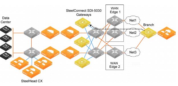
Data center gateway cluster topology
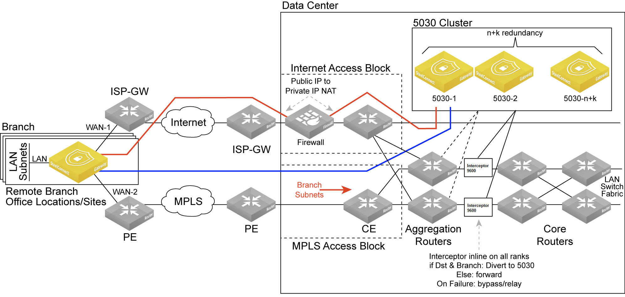
The software-defined WAN (SD-WAN) functionality shown in
Data center gateway cluster topology is comprised of two SteelHead Interceptors and a SteelConnect data center gateway cluster. The SteelHead Interceptors provide scalable data referencing (SDR)-aware load balancing and network traffic redirection.
The SD-WAN topology requires minimal routing interaction and provides graceful failover, scalability, and easy upgrades to existing configurations.
A 5030 gateway acts as a termination point for all overlay tunnels coming into a data center location from the branch offices.
A 5030 gateway only serves a subset of branch traffic: overlay-to-underlay conversion ingress and underlay-to-overlay redirection on egress. In addition to serving data center-bound overlay traffic, a 5030 gateway can act as a common gateway across many branches. The data center gateway achieves integration with the network underlay using External Border Gateway Protocol (eBGP) peering with WAN aggregation routers in the data center, as shown in
Data center gateway cluster topology.
The 5030 gateway is aware of any non-SteelHead sites connected to the network and lets those sites know of any SteelConnect-enabled branches and data centers on the WAN.
Use SteelConnect Manager (SCM) to create and configure the gateways as out-of-path clusters on your network. SCM supports one cluster per site. Each gateway in a 5030 cluster is physically connected to SCM using an out-of-band management connection.
The 5030 gateway doesn’t interact with LAN switches or access points, and it doesn’t include a built-in perimeter firewall.
Cluster components
A 5030 gateway cluster is simply three or more 5030 gateways stacked together and wired to the data center. A minimum of three 5030 gateways in a cluster is required to provide single gateway fault protection.
A cluster uses Layer 2 full-mesh interconnectivity between the individual gateways using direct interconnect for cluster spanning for multiple gateways or an external switch.
A 5030 gateway cluster is made up of these components:
•Cluster nodes - The individual physical 5030 gateways in the cluster.
•Data center uplinks - The network segments that connect to available WANs. Data center uplinks notify SteelConnect which WANs are available for building 5030 gateway tunnels across.
•Overlay tunnel endpoints (TEPs) - The IP addresses that provide the reachability information for a branch to a data center. You can think of TEPs as the on and off ramps to the overlay network. Traffic enters and leaves the overlay through a TEP.
•Site pool - A collection of branches grouped together to communicate with a data center. Site pools provide a way to share the branch traffic load.
•Site map - A resource allocation method that tracks how a site cluster is serving the site traffic at any point in time to maintain high availability for the data center gateways. The site map tracks which site pool is associated with which data center node.
Attracting branch traffic toward data center gateways
SteelConnect can steer traffic bound for branches to the data center gateways using a SteelHead Interceptor 9600 to intercept the traffic and tunnel it to the data center gateways using generic routing encapsulation (GRE). After creating the data center gateway cluster, you enable communication between the gateways in the cluster and the SteelHead Interceptor sending traffic to the cluster by entering the sd-wan and sd-wan communication CLI commands on the SteelHead Interceptor. For details on these CLI commands, see the Riverbed Command-Line Interface Reference Manual.
For details on the SteelHead Interceptor, see
Changing the default gateway configuration and the
SteelHead Interceptor Deployment Guide.
Creating clusters
Before configuring a data center gateway cluster, you must add at least three 5030 gateways to a site. All of the 5030 gateways must be:
•cabled on the WAN side.
We recommend that the gateways be cabled identically for redundancy.
A cluster is limited to 256 nodes.
Configuring ports
Each of the 5030 gateways use ports 1 and 2 for system-related tasks. The remaining ports are used as data ports.
•Port 1 - Management port dedicated to SCM. Requires connectivity to a network with internet access to facilitate calls to SCM. The SteelHead Interceptor must be able to reach this port.
•Port 2 - Dedicated cluster connectivity port, providing an internal, private physical connection between the 5030 gateways for cluster synchronization and high availability. All 5030 gateways must be Layer 2 adjacent in this network.
•Port 3 - Data port for WAN-facing connectivity, which can optionally be used for high availability.
•Ports 4-10 - Data ports for WAN-facing connectivity.
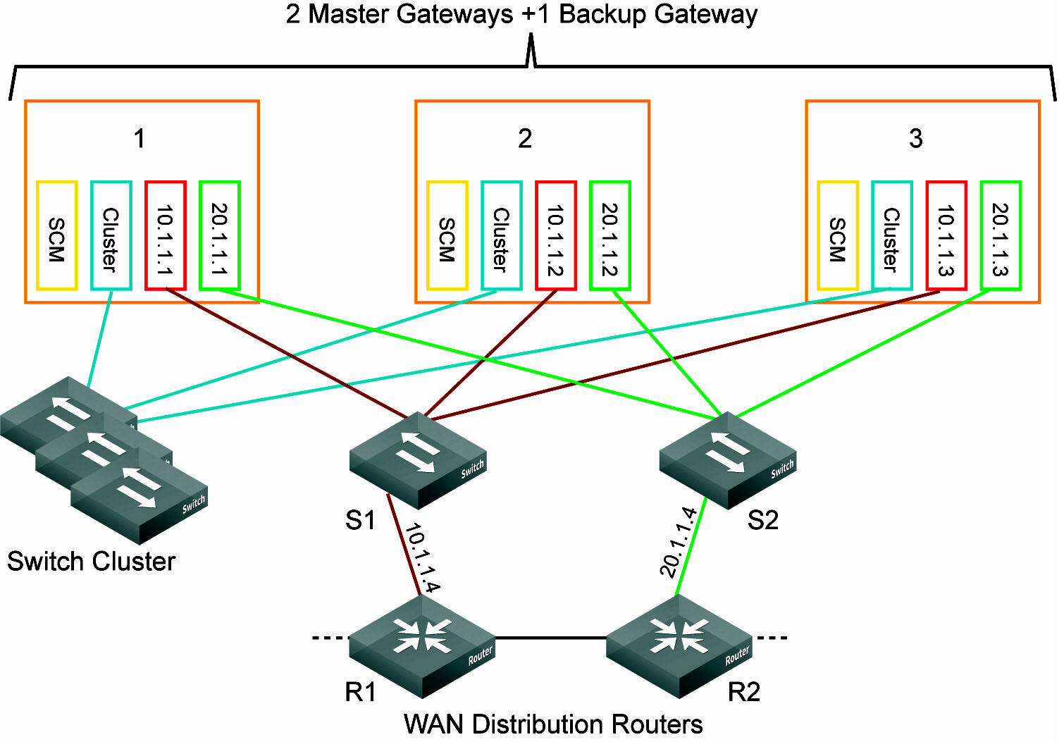
Data center gateway cluster connectivity assumes that there are two WANs available.
Data center gateway cluster connectivity
To create a data center gateway cluster
1. Choose Network Design > Clusters.
2. Click New Cluster.
3. Specify a cluster name.
4. Select the site to deploy the cluster from the drop-down list.
Tip: In a cluster workflow, it can become difficult to differentiate between data center gateways in a cluster when they are referenced on various SCM pages. We strongly recommend that you always specify a detailed location for the gateway using the Location field under the Location tab in the appliance page. Setting the location associates a gateway with its location wherever an appliance is referenced, making it easy to identify.
5. Select the cluster members from the drop-down list.
6. Specify the number of failover nodes. By default, the system creates one failover node in a cluster of three 5030 gateways.
7. Select On to accept communications from an integrated SteelHead Interceptor 9600 running version 5.6.0 or later with 5030 gateways to help route and optimize network traffic.
8. Specify the IP address the Interceptor will use to communicate with the cluster. The IP address has to be on the management network for the cluster.
9. Click Submit.
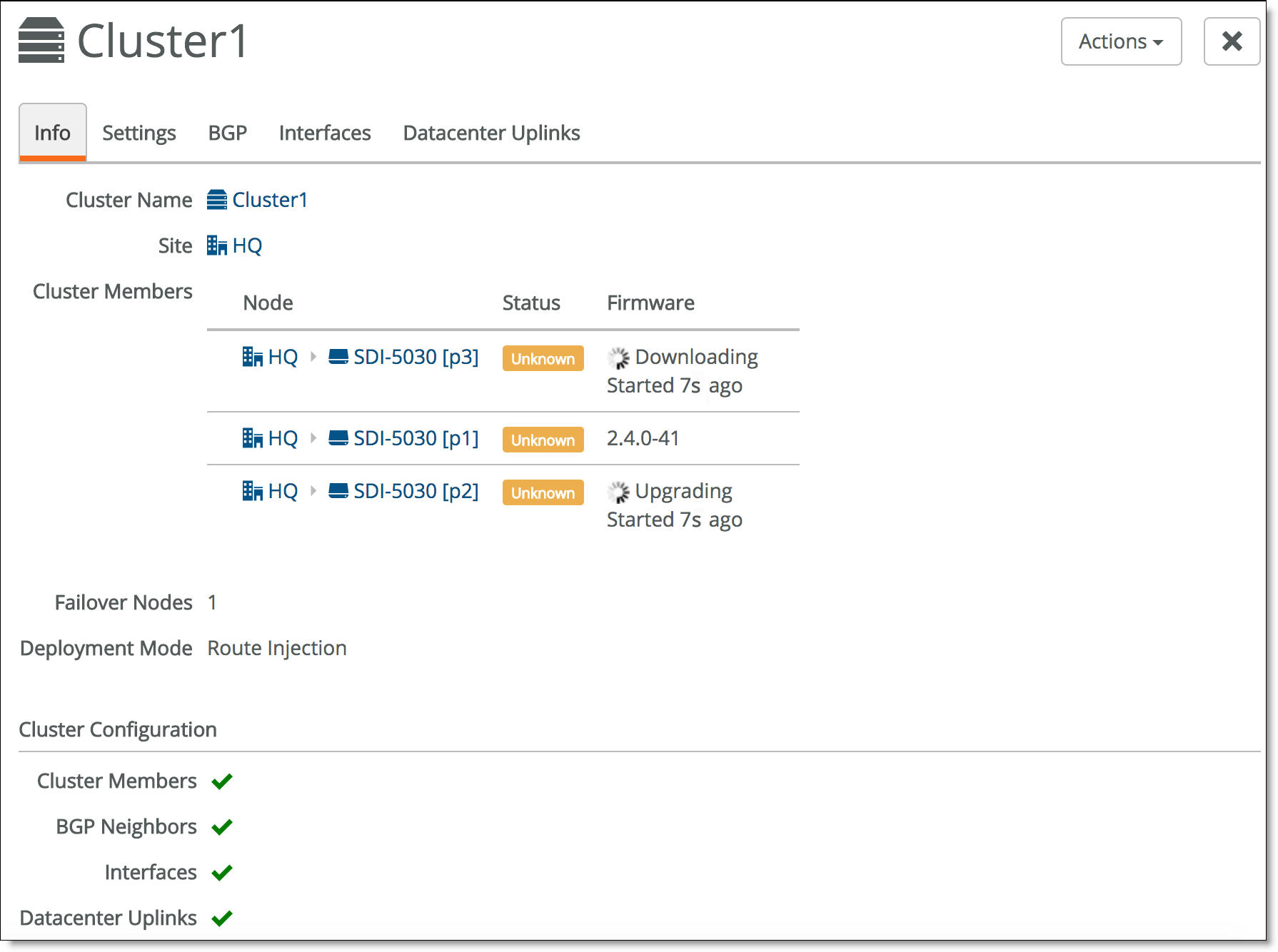
Select the cluster from the Clusters page and select the Info tab to view the cluster’s health. The individual cluster member status appears at the bottom of the page under cluster configuration.
Cluster configuration
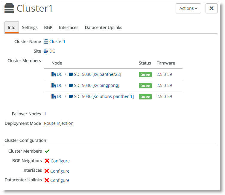
A green check mark lets you know that the item is configured correctly. A red x appears next to any item that needs attention. When a green check mark appears next to each item under Cluster Configuration, the cluster is configured correctly. In
Cluster configuration, a red x appears after three items, indicating that you also need to configure BGP neighbors, interfaces, and data center uplinks before the cluster configuration is complete. Selecting the link next to the red x takes you to the configuration page where you can fix the issue.
Creating data center uplinks
A data center uplink physically connects the cluster to a WAN. A cluster must have at least a single uplink or multiple uplinks to the same WAN and can connect to multiple WANs. You can use multiple uplinks to the same WAN for redundancy.
You need to bind an uplink to a cluster and a WAN. You also need to enter an IPv4 and IPv6 address for each IP set, per uplink. The data center uplink is restricted to the IP subnet.
To create an uplink
1. Choose Network Design > Clusters.
2. Select a cluster to associate with the uplink. Each uplink is cluster-specific and its connection type differs between clusters.
3. Select the Datacenter Uplinks tab.
4. Click Add Datacenter Uplink.
Data center uplink
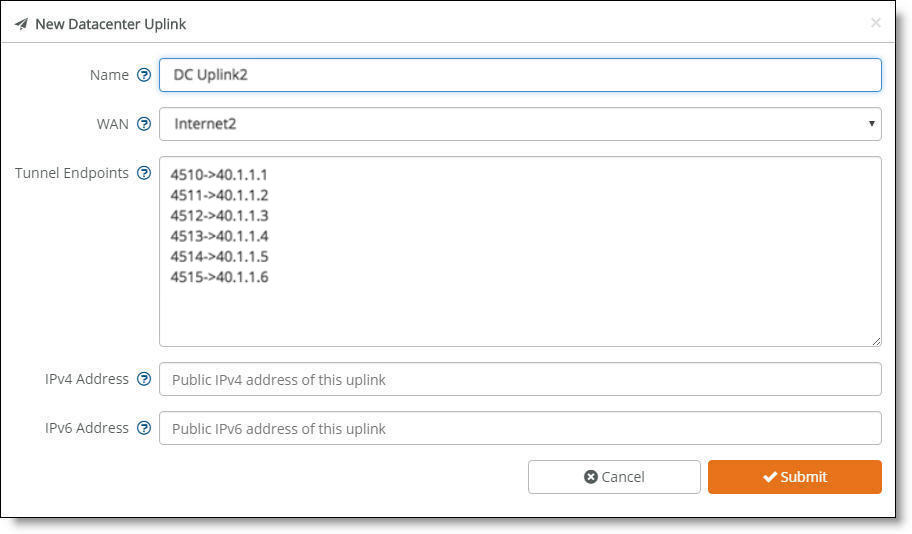
5. Type the uplink name: for example, DC Uplink2. Each uplink name must be unique.
6. Select a WAN.
5030 gateways are deployed out of path in the data center. To deploy path selection with a 5030 gateway, you must enable encryption on the WAN. When encryption is disabled on a WAN, the packets are not put on any tunnel. This means that the packets from the remote branch to the 5030 gateway in the data center will use the destination IP address and not the 5030 gateway’s WAN interface. As a result, packets won't be sent to the 5030 gateway. With encryption enabled, packets will reach the data center because the 5030 gateway will send the packets to the original destination on the LAN. For details, see
WAN settings.
7. Identify how the branch gateway will reach the correct data center gateway by specifying the tunnel endpoints for each gateway in the cluster: for example, 40.1.1.1. For three appliances in the cluster, add two tunnel endpoints for each gateway, resulting in six endpoint IP addresses. You can also use a netmask subnet and SCM will allocate the endpoints.
You can also specify a public IP’s corresponding NAT port along with the tunnel’s endpoints.
8. Specify the public IPv4 address of the uplink with an optional netmask. This address is required for Internet WANs and optional for other WANs.
9. Click Submit.
Creating interfaces
Each 5030 appliance must have at least one interface.
To create an interface
1. Choose Network Design > Clusters.
2. Select a cluster to associate with the interface.
3. Select the Interfaces tab.
4. Click Add Interface.
5. Select a data center port from the drop-down list. Click the search box to search for a port.
6. Specify the IPv4 address and netmask to the 5030 gateway. The netmask is required. Use this format for an individual subnet IP address and netmask: xxx.xxx.xxx.xxx/xx
7. Specify the IPv6 address for the interface. Use this format for an individual subnet IP address and netmask: x:x:x::x/xxx
8. Specify the MTU value. The MTU is the largest physical packet size, measured in bytes, that a network can send. The default value is 1500.
9. Click Submit.
10. Repeat steps 4 through 9 to add more interfaces one at a time.
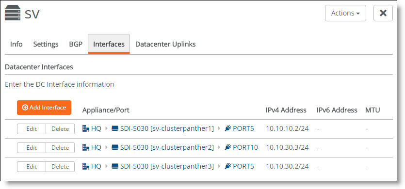
You can select the Interfaces tab to view the interfaces for a cluster.
Interfaces associated with a cluster
The next task is to configure the BGP settings to enable dynamic routing for a cluster. This task is required.
Why enable dynamic routing for a cluster?
The 5030 gateways use eBGP for dynamic routing within the data center. Each 5030 gateway in a cluster forms eBGP peering with the data center routers. The global BGP settings:
•establish eBGP neighbor relationships with the provider edge (PE) routers.
•enable the data center gateway to learn routes from the WAN uplinks.
Enabling dynamic routing for a data center cluster provides reachability information for the following scenarios.
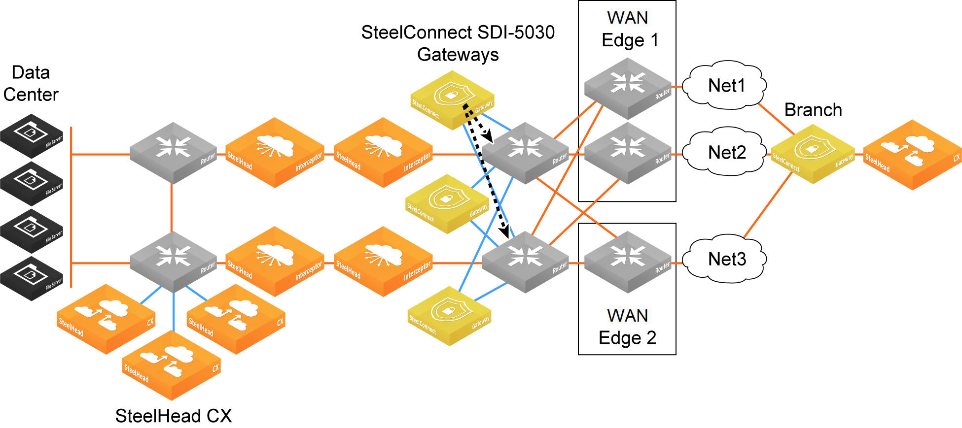
Forwarding packets from the branch to the data center gateway
Because the data center network needs to know how to forward tunneled packets from the branch to the correct 5030 gateway, you have to define the 5030 gateway tunnel endpoints in the underlay.
SteelConnect doesn’t support IPv6-based tunnel endpoints (TEPs).
Forwarding from the branch to the data center
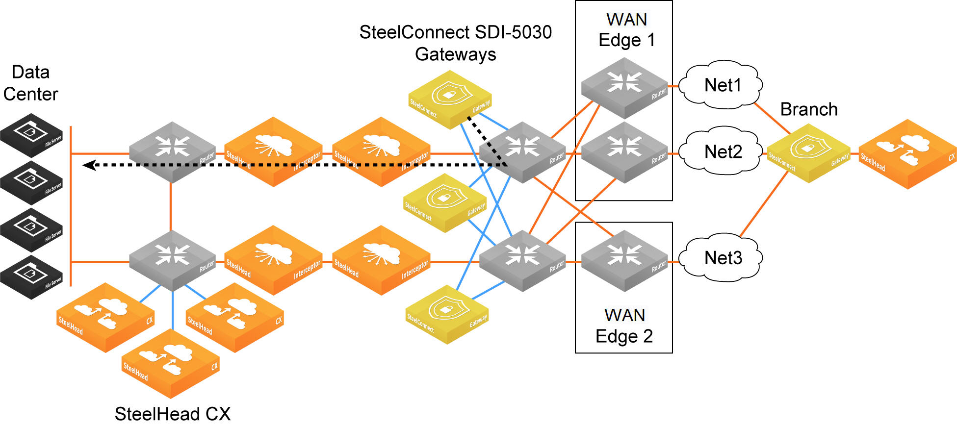
Forwarding packets from the data center gateway to the branch
Because there can be multiple routers going to different WAN edges in the network, the 5030 gateway needs to know how to forward outgoing tunneled packets heading to the branch to the correct data center router. The data center router informs the 5030 gateway about the branch TEP reachability.
Forwarding from the data center to the data center router en route to the branch
Forwarding inner connections to the data center
The 5030 gateway must know how to forward deencapsulated inner packets to the appropriate data center router. The data center router must tell the 5030 gateways about the data center subnet reachability.
Forwarding inner connections through the data center router
Configuring BGP settings
This routing information flows between the eBGP peers:
•The 5030 gateway informs the data center aggregation routers of its TEP addresses that terminate on the 5030 gateway.
•In the opposite direction, the data center’s aggregation routers communicate to the 5030 gateways all of the prefixes they need to route to data center subnets, including branch TEP addresses and the branch subnets for all non-SD-WAN branches.
Each appliance must have at least one BGP neighbor.
BGP routing is also needed for cluster high availability. For details, see
eBGP and high availability.
For more information on dynamic routing with BGP, see
Branch dynamic routing topologies with eBGP.
First, configure the individual 5030 appliances with local information.
To configure BGP for a 5030 appliance
1. Choose Appliances.
2. Select an appliance.
3. Select the BGP tab.
4. Fill out these required session attributes:
•Router ID - Specify the router IPv4 or IPv6 address to uniquely identify the router in the local autonomous system (AS). The gateway can peer with any remote router that supports eBGP. eBGP must be enabled on the router.
•Local AS - Specify the AS number the router belongs to: for example, 100. The range is from 1 to 4294967295.
Next, configure the BGP information for the cluster. The cluster needs the router information needed to communicate with the 5030.
To configure BGP for a data center cluster
1. Choose Network Design > Cluster.
2. Select a cluster.
3. Select the BGP tab.
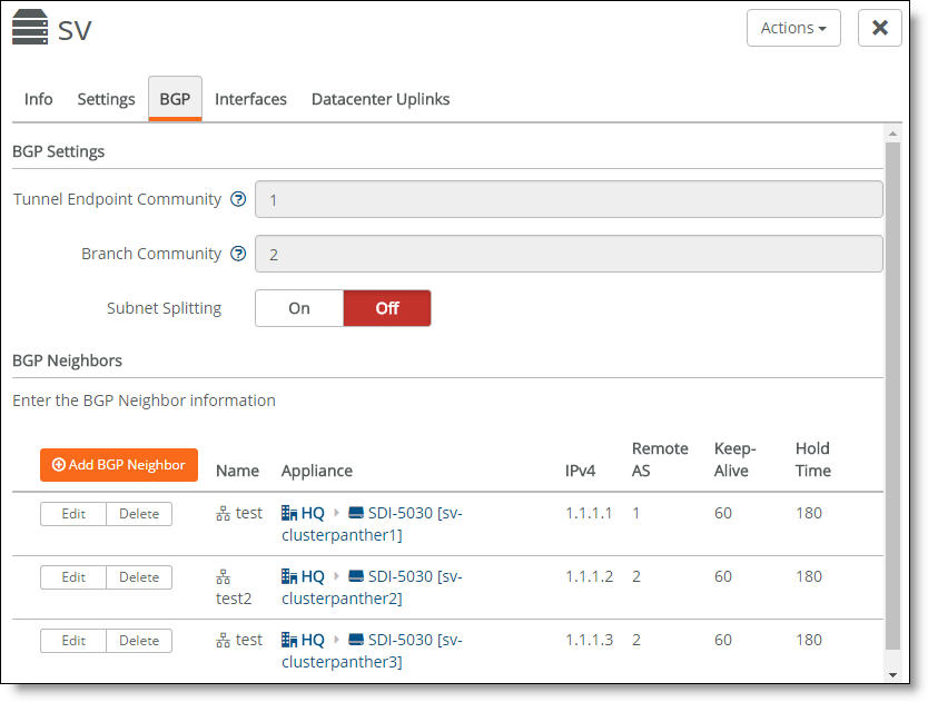
4. Fill out these BGP settings:
•Tunnel Endpoint Community - Restricts traffic entering a tunnel by tagging route advertisements to a BGP peer with a community attribute. Specify a community name in the format AA:NN or a number between 1 and 65535.
The same community attribute is applied to all route advertisements from the gateway. The Tunnel Endpoint (TEP) Community tag and the Branch Community tag must be different.
You don’t need to have a community attribute for each unique subnet and zone advertised.
•Branch Community - Restricts traffic entering a tunnel by tagging route advertisements to a BGP peer with a community attribute. Specify a community name in the format AA:NN or a number between 1 and 65535.
The same community attribute is applied to all route advertisements from the gateway. The Branch community tag and the TEP community tag must be different.
You don’t need to have community attribute for each unique subnet and zone advertised.
•Subnet Splitting - When disabled, the gateway advertises the regular branch subnet prefixes (BSPs) for which it is responsible to its eBGP peers. When enabled, the gateway withdraws the BSPs and instead advertises the corresponding split subnets. When disabled, the system withdraws the split subnets and advertises the BSP as received. By default, subnet splitting is off.
5. Click Add BGP Neighbor.
6. Specify a name for the neighbor.
7. Select an appliance from the drop-down list.
8. Specify the neighbor’s IPv4 address.
9. Specify the ASN number the neighbor belongs to: for example, 100. The range is from 1 to 4294967295.
10. In the Password field, type a password to enable MD5 authentication. You must use the same password on both BGP neighbors. If you don’t require MD5 authentication, you can leave this field blank.
11. In the Keep Alive Time field, specify the amount of time, in seconds, that the eBGP neighbors exchange keepalive messages to determine whether a link has failed or is no longer available. The neighbors exchange keepalive messages often enough so that the hold time does not expire. The default setting is 60 seconds.
12. In the Hold Time field, specify the amount of time, in seconds, that a gateway neighbor waits for an incoming keepalive, update, or notification message from a neighbor before it assumes its neighbor is down. If the gateway doesn’t receive a keepalive, update, or notification message from its neighbor within the period specified, it closes the connection and routing through that neighbor becomes unavailable.
A 0 value means that no keepalive messages are sent and the connection will never close. The hold-time range is from 0 to 65535. The default setting is 180 seconds (three minutes).
The hold-time value is three times the interval at which keepalive messages are sent. Using the default values for the keepalive time of 60 and the hold time of 180, the settings work together like this: after two neighbors establish an eBGP session, 60 seconds later they’ll each send a keepalive message. When a gateway receives a keepalive message from its neighbor, that gateway’s hold time for the session will have counted down from 180 to 120, but it’s then reset to 180. This process continues every 60 seconds. However, should neighbor A lose power, then neighbor B won’t receive any keepalives. So after 180 seconds, neighbor B determines that neighbor A is down and closes the session.
13. Click Submit.
14. Repeat steps 5 through 13 to create additional neighbors one at a time.
Select the BGP tab to view the BGP neighbor configuration for a cluster.
BGP neighbors for a cluster
Special consideration for iBGP and eBGP deployments
Deployments that use a combination of eBGP and iBGP require some special configuration on the routers.
5030 gateway deployment combining eBGP and iBGP
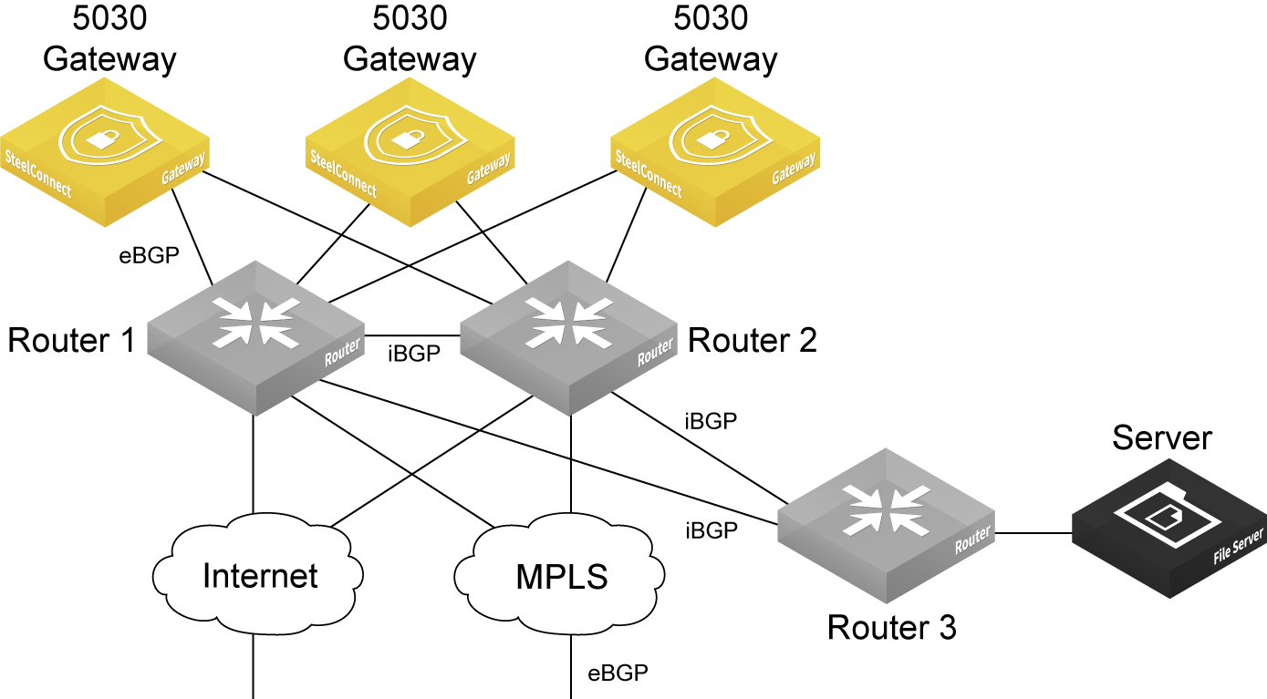
In this topology, the interior gateway protocol (IGP) in the data center underlay is iBGP, and the MPLS WAN side is using eBGP. eBGP is in use between the 5030 gateways, router 1, and router 2. The 5030 gateways advertise the branch prefixes and TEPs into the underlay through eBGP, with the next hop as self.
iBGP will advertise these routes but it won’t update the next hop of routes advertised by the 5030 gateways. Because the 5030 gateway cluster requires an eBGP session with next hop routers, this requirement will have an effect on traffic if one of the WDRs through which the routes were reachable was to go down. This is a known configuration and an industry practice. This scenario requires additional CLI configuration on the routers.
For example, configure the router 1 through router 3 iBGP session or the router 2 through router 3 iBGP session like this:
On router 1
router bgp 1
neighbor <R3 interface IP address> remote-as 1
neighbor <R3 interface IP address> next-hop-self
On router 2
router bgp 1
neighbor <R3 interface IP address> remote-as 1
neighbor <R3 interface IP address> next-hop-self
Advertising the default route in IGP in the data center for internet uplinks
The packets from the remote branch to the gateway cluster in the data center on the internet uplink use the source IP address as the public IP address for the remote branch. They also use the destination IP address as the public IP address for the data center. Because the destination IP address gets NATed on the internet router or the firewall to the 5030 gateway's TEP IP, the remote branch is able to send packets to the 5030 gateway cluster.
But the overlay traffic from a 5030 gateway to the remote branch could fail because the source IP address will be the 5030 gateway's TEP and the destination IP address will be the public IP address of the remote branch—which is not advertised in the data center underlay.
To enable the 5030 gateway to learn the default route, the network administrator or engineer for the data center must redistribute the default route into the IGP of the data center and also into the BGP session with the 5030 cluster. After the 5030 learns the default route, it knows how to send packets out to the remote branch on the internet uplink.
Secure overlay tunnels
SteelConnect establishes secure overlay tunnels between a data center cluster and branch gateways. The overlay tunnels are secured using centralized virtual private network keying (C-VPN-K). Traffic is encrypted by the Advanced Encryption Standard (AES) cipher algorithm in Cipher Block Chaining (CBC) mode using a 256-bit key. For secure authentication, centralized VPN keying uses the hash message authentication code (HMAC) secure hash algorithm (SHA512).
By default, centralized keying is turned off for branch gateway-only (non-5030) deployments. When centralized keying is off, gateway-to-gateway tunnels are established with IKEv2 using the same encryption and authentication algorithms as centralized keying.
Centralized keying can be enabled for a given realm when the realm contains a 5030 gateway. When centralized keying is enabled, both branch gateway-to-branch gateway and branch gateway-to-data center gateway (5030) tunnels within that realm use centralized keying.
Secure overlay tunnels use centralized VPN keying
Deployment considerations
•For centralized keying to work, you must enable encryption for all WANs, including MPLS. For details, see
WAN settings.
•5030 gateways don’t support IKEv2.
•We recommend using NTP time synchronization to synchronize the branch and data center gateways. Complete this procedure on each branch and data center gateway in the deployment.
To synchronize the date and time using NTP servers
1. Choose Organization.
2. Select the Networking Defaults tab.
3. Under NTP settings, specify the local Network Time Protocol (NTP) servers of your choice, one per line. We recommend that you configure your own internal NTP servers; however, you can leave the field blank to use these default Riverbed-provided NTP servers:
•0.ocedo.pool.ntp.org
•1.ocedo.pool.ntp.org
•2.ocedo.pool.ntp.org
•3.ocedo.pool.ntp.org
4. Click Submit.
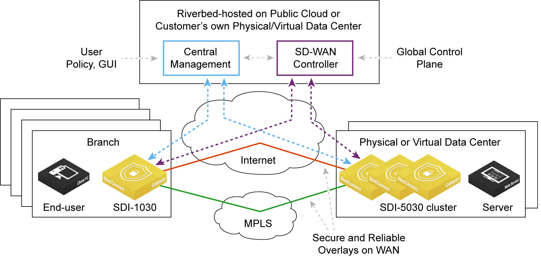
SD-WAN controller
SCM and the SD-WAN controller reside within the Riverbed-hosted cloud environment. The SD-WAN controller listens to configuration changes made by the user through the SCM, such as adding new sites. The SD-WAN controller reacts to any configuration changes and, if required, creates new tunnels between the branch gateways and the data center 5030 gateway cluster to account for the changes.
The SD-WAN controller owns and manages all centralized VPN keys.
Key management, retrieval, and rotation
The 5030 gateways must connect to the SD-WAN controller with their management port. When a 5030 gateway cluster is configured and centralized keying is enabled for the realm, the SD-WAN controller generates unique VPN keys for each tunnel.
The data center gateway receives the encryption keys from the controller through an SSL connection on TCP port 3904. TCP port 3904 must be open on the corporate firewall in order for the gateways to pull the keys securely.
The branch gateways already have a secure connection to the controller in the cloud and use this connection. You don’t need to open an additional port on the firewall for the branch gateways.
•The gateways store the keys locally for use until the rekey interval expires.
•The keys are changed every four hours or when a new tunnel endpoint (TEP) appears.
•The gateways change from the old to the new keys during a rekeying event and apply the new keys to the existing tunnels.
•Each gateway is only aware of the keys used to secure its own tunnels.
Key resiliency
•SCM services related to centralized keying are fault tolerant and don’t affect AutoVPN connectivity when restarted.
•The centralized keys are resilient to complete loss of connectivity to SCM for extended periods (about one day).
•The keys are resilient to asymmetric loss of connectivity to SCM, such as when only one gateway receives a configuration update.
Viewing cluster health
1. Choose Network Design > Clusters.
The cluster health appears.
Cluster health
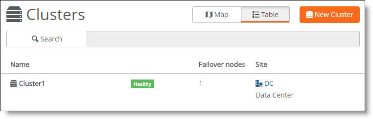
A cluster’s health falls into one of these categories:
•Healthy - Indicates that all gateways in the cluster are operating normally.
•Degraded - Indicates that all gateways in the cluster aren’t operating normally. The cluster is unprotected by redundancy but is operational.
•Unhealthy - Indicates a loss of quorum resulting from one or more gateways in the cluster going offline or failing.
•Unknown - Indicates the lack of status updates because the connection to SCM is down.
2. For more details, select the cluster.
3. Select the Info tab.
The individual cluster member status appears. A red x appears next to any item that needs attention. Selecting the link next to the red x takes you to the configuration page where you can fix the issue. When you return to the cluster info page, a green check mark lets you know that the item is configured correctly. When a green check mark appears next to each item under Cluster Configuration, the cluster is configured correctly.
The system reports cluster health status for individual cluster members during the initial cluster configuration; it doesn’t reflect runtime status. To view cluster runtime events, view the event log. The event log reports cluster status events in 15-second intervals.
Cluster health status
Because SCM has direct visibility into the appliances, you can also investigate the status of the individual gateways within a cluster using the Appliances Overview page. You can correlate the gateway’s status with the overall cluster health because each gateway contributes to the cluster health.
To view a data center appliance status
1. Choose Appliances > Overview.
2. Find the data center gateways belonging to the cluster in the appliance list.
3. Check the appliance configuration status.
•Up to date - Indicates that appliance is running the most recent configuration.
•Pending - Indicates that the appliance hasn’t yet received the pushed configuration and the appliance is offline.
•Firmware upgrade - Indicates that a new firmware version has been downloaded to the appliance but the firmware version hasn’t been updated yet. For details on upgrading the individual appliances belonging to a cluster, see
Upgrading a data center cluster.
When one of the appliances in a cluster is offline, SCM reports an unhealthy cluster.
Deleting a cluster
Deleting a cluster deletes all data center uplinks associated with the appliances. The interfaces and BGP neighbors are not deleted and are still available as part of the individual 5030 appliance configurations.
1. Choose Network Design > Clusters.
2. Select a cluster.
3. Click Actions and then select Delete this cluster from the drop-down menu.
A dialog asks for confirmation.
Deleting a cluster confirmation
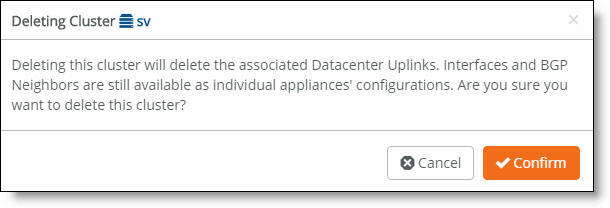
4. Click Confirm.
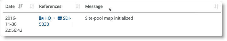
Viewing cluster status events
You can also check the event log to determine whether the system has initialized the site pool map for the cluster. The site pool map is initialized when the cluster configuration is complete and the cluster determines how it is going to handle the site pools using its physical resources. A site pool map initialization event indicates that the cluster has sent a site pool map to SCM and is ready to handle traffic flows.
Cluster status events are reported in 15-second intervals.
To view events
•Select the Events tab or choose Visibility > Event Log.
SCM site pool initialization event
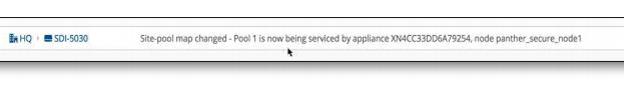
SCM also captures high-availability failover events that result in a site pool assignment change, as shown in
SCM site pool change event.
SCM site pool change event
How does SteelConnect allocate resources within a cluster?
During provisioning, the system matches a site pool to a data center gateway belonging to a cluster, creating a site map.
Site pools are used for data center resiliency to ensure that in the event of a physical appliance, software, or link failure, the data center can keep track of the physical branch gateways so that their perception of IP reachability doesn’t change after a failure. Site pools allow network nodes to be dynamically provisioned while improving failover performance time and ensuring that there is never a single point of failure.
Site pools contain abstractions of physical appliances using a virtual entity. The system uses the abstractions to provide seamless high availability without having to coordinate all of the components across the entire topology. The branches are segregated into separate site pools using a round robin algorithm, so if a data center gateway fails, it impacts only a subset of the branches.
The system assigns one of the site designator instances in the lead role to be in charge of site assignment coordination across the entire cluster. The site designator splits the branch sites into two distinct site pools, such as site pool 1 and site pool 2, during provisioning. After assuming the lead role, the site designator takes an inventory of the data center gateways that can be tasked with servicing individual site pool assignments.
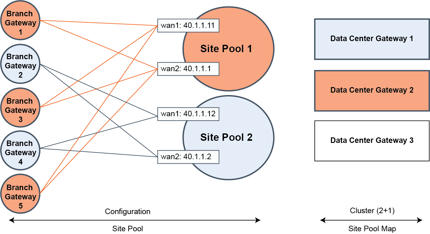
In
Site pool and map assignments, the site map designates data center gateway 2 with an active service assignment for site pool 1. The initial site pool assignment ensures backup service using data center gateway 1. After an appliance failure on data center gateway 2, the system reassigns site pool 2 flows to the backup data center gateway 1. No further changes to service assignment need to happen when the data center gateway 2 recovers from the failure. For details on high availability, see
How does data center high availability work?.
Site pool and map assignments
Multiple site pools are processed by a single 5030. In terms of CPU resource allocation, there is a fixed amount of CPU processing allocated to each site pool.
A bin packing algorithm balances the resource consumers (traffic processing to and from the remote sites) with the resource producers (the CPU cycles required to process the traffic). Resource consumption is directly proportional to site size.
For a first approximation to place resource consumers into site pools, SteelConnect provides a uniform distribution of small, medium, and large sites into all site pools. For example, suppose you have “x” small sites, “y” medium sites, and “z” large sites allocated between four site pools (A, B, C, and D). An ideal allocation of resource consumers to site pools is to allocate one quarter of all sites (x, y, and z) to each site pool (A, B, C, and D).
The default site size is medium. You can adjust the distribution of resource consumers based on site size. The small, medium, and large site sizes are relative to ensure efficient bin packing with a fair distribution.
To adjust the distribution of resource consumers by site size
1. Choose Network Design > Sites.
2. Select a site.
3. Select the Size tab.
4. Choose a site size from the drop-down list: small, medium, or large.
5. Click Submit.
Changing the site size might reassign it to another 5030 in the cluster, depending on how the system redistributes the resources.
How does SteelConnect allocate site pools with multiple cluster uplinks?
Each 5030 gateway can handle multiple site pools.
When a data center cluster has multiple uplinks, SCM uses tunnel endpoints (TEPs) from each uplink to create a pool. For example, suppose that there are six to ten remote sites and the cluster uplink 1 has TEPs T1 and T3. Cluster uplink 2 has TEPs T2 and T4. In this example, SteelConnect creates one pool with TEPs T1 and T2 with remote sites R1 to R5, and another pool with TEPs T3 and T4 with remote sites R6 to R10.