Configuring Network Integration Features
This chapter describes how to configure network integration features such as Interceptor-to- Interceptor (or SteelHead) communication, WCCP, port labels, and Xbridge. It includes the following sections:
Note: This chapter assumes that you have installed and performed the initial configuration of the SteelHead Interceptor. For details, see the SteelHead Interceptor Installation Guide.
Configuring Interceptor-to-Interceptor Communication
You use the SteelHead Interceptors page to configure the SteelHead Interceptor’s connection-forwarding settings and Interceptor-to-Interceptor communication list. Connection-forwarding settings specify how the appliance is to communicate with the other SteelHead Interceptor or appliances in the communication list.
If you deploy more than one SteelHead Interceptor per site, you must configure each SteelHead Interceptor to interact with every other Interceptor in one of two ways: as a failover Interceptor or as a cluster Interceptor.
• Failover Interceptors are pairs of serially connected SteelHead Interceptors. You deploy two SteelHead Interceptors physically in-path on all of the same physical links, and each appliance is configured to act as a backup for the other appliance for the same network links. If one appliance goes down or needs maintenance, the other appliance handles redirections for the connections over those links.
• Cluster Interceptors are two or more connected SteelHead Interceptors that are not necessarily serially connected. You configure peer SteelHead Interceptors to cover different network paths, typically parallel paths. This design enables SteelHead Interceptors to forward connections in an asymmetrically routed network.
A SteelHead Interceptor communicates with other SteelHead Interceptors over TCP connections on the enabled in‑path logical interface (or all interfaces, if multi-interface support is configured) that you designate for Interceptor-to-Interceptor communication. This applies to both failover and cluster Interceptors.
Note: Even if an appliance is deployed as a single SteelHead Interceptor that does not communicate with other SteelHead Interceptors, you must select an enabled in-path interface for Interceptor-to-Interceptor communication. If you do not enable the Communicate with Interceptor Using This Interface option and then choose the Interface drop-down list item that specifies an enabled in-path interface, the Interceptor service fails to start.
To enable connection forwarding, you must configure the Interceptor-to-Interceptor communication list on both failover Interceptors, or on all cluster Interceptors, so that the respective lists point to the IP address of the Interceptor-to-Interceptor communication interfaces of the other appliance or appliances in the set.
Parallel Deployments
In networks where servers are physically dispersed, connection requests and responses might take asymmetric paths. To correct this condition, you can deploy SteelHead Interceptors along each parallel path, as shown in
Figure: Parallel Deployment in Asymmetric Networks.
Figure: Parallel Deployment in Asymmetric Networks
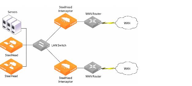
When you configure these SteelHead Interceptors as a cluster, an appliance checks for related packets before forwarding the connection. The first appliance to send the request becomes the one that consolidates all packets for the connection and the only one to forward the connection, thereby eliminating the asymmetric route. The configuration steps are described in
Configuring Interceptor-to-Interceptor Communication.
Serial Deployments
To deploy failover, you configure a pair of SteelHead Interceptors in a serial configuration. Connect the LAN in-path interface of the WAN-side SteelHead Interceptor using a crossover cable to the WAN in-path interface of the LAN-side SteelHead Interceptor, as shown in
Figure: Serial Deployment to Provide Failover Support.
Figure: Serial Deployment to Provide Failover Support
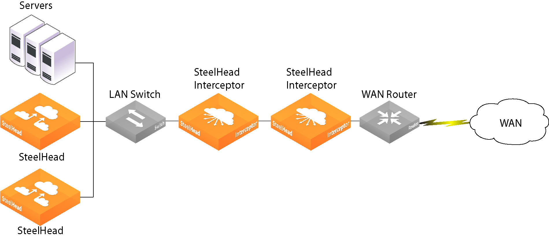
To configure failover, you configure each SteelHead Interceptor as a failover
Interceptor for the other. The configuration steps are described in
Configuring Interceptor-to-Interceptor Communication.
Quad Deployments
A quad deployment offers the highest availability. Each inline SteelHead Interceptor serves as a failover Interceptor for the other. Both inline SteelHead Interceptors serve to forward connections for the parallel SteelHead Interceptors. Connect the LAN in-path interface of the WAN-side SteelHead Interceptor using a crossover cable to the WAN in-path interface of the LAN-side SteelHead Interceptor, as shown in
Figure: Quad Deployment to Provide Failover Support.
Figure: Quad Deployment to Provide Failover Support
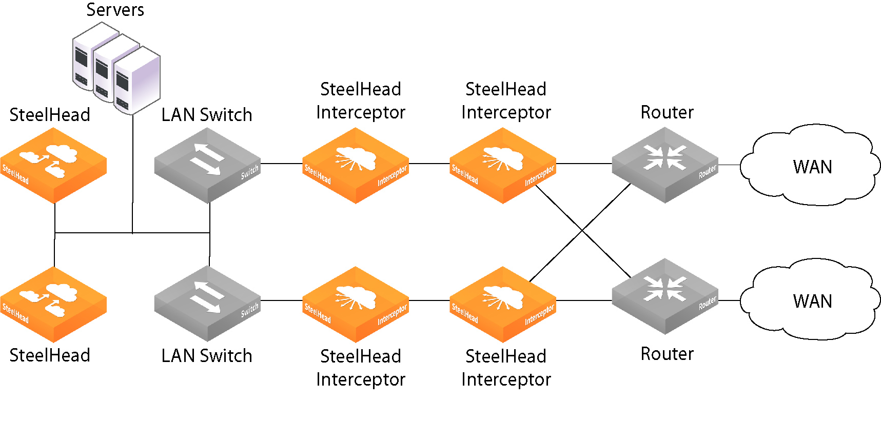
Failover eliminates routing convergence if an appliance fails; optimization continues even in the event of router or switch failure.
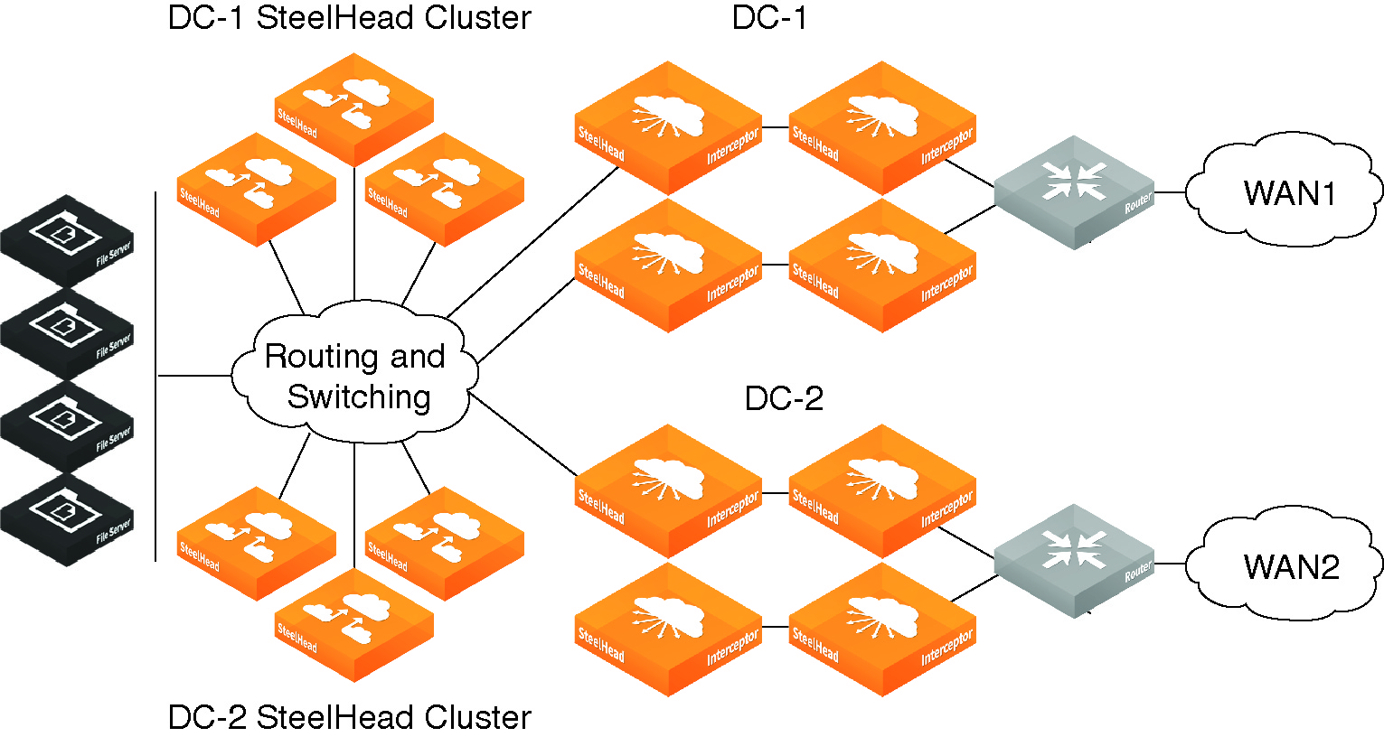
Octal Deployments
An octal deployment (
Figure: Octal Deployment) consists of two quad deployments split across a data center.
Figure: Octal Deployment
Before You Begin
Before you configure Interceptor-to-Interceptor communication, check that configuration requirements are met, and note the configuration recommendations.
Before you configure Interceptor-to-Interceptor communication, you must enable the in-path interface or interfaces that will be designated for Interceptor-to-Interceptor communication on this appliance:
• If you are not enabling multi-interface support on the SteelHead Interceptor, you must enable an in‑path interface before you can select it as the single Interceptor-to-Interceptor communication interface.
• If you are enabling multi-interface support on the SteelHead Interceptor, you must enable at least one in-path interface.
Riverbed also recommends the following practices when configuring Interceptor-to-Interceptor communication:
• Ensure that LAN-side next hops reach other Interceptor in-path interfaces on different subnets by configuring at least one of the following settings on the SteelHead Interceptor:
– Default gateway IP address
– Static routes for reaching Interceptor in-path interfaces on different subnets
• When you add to the Interceptor-to-Interceptor communication list a SteelHead Interceptor that is enabled for multi-interface support, Riverbed recommends that you specify the IP addresses of all of the enabled in-path interfaces on that appliance.
To configure Interceptor-to-Interceptor communication
1. Display the SteelHead Interceptors page in either standard mode or VLAN segregation mode.
The location of the SteelHead Interceptors page depends on whether the SteelHead Interceptor is running in standard mode or VLAN segregation mode:
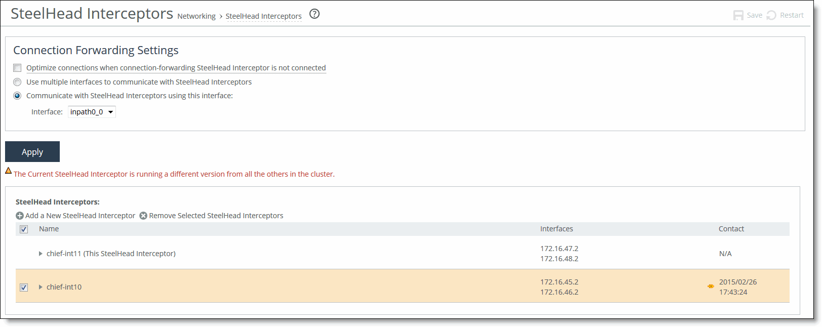
• Standard mode - Choose Networking > Network Services: SteelHead Interceptors to display the SteelHead Interceptors page.
Figure: SteelHead Interceptors Page (Standard Mode)
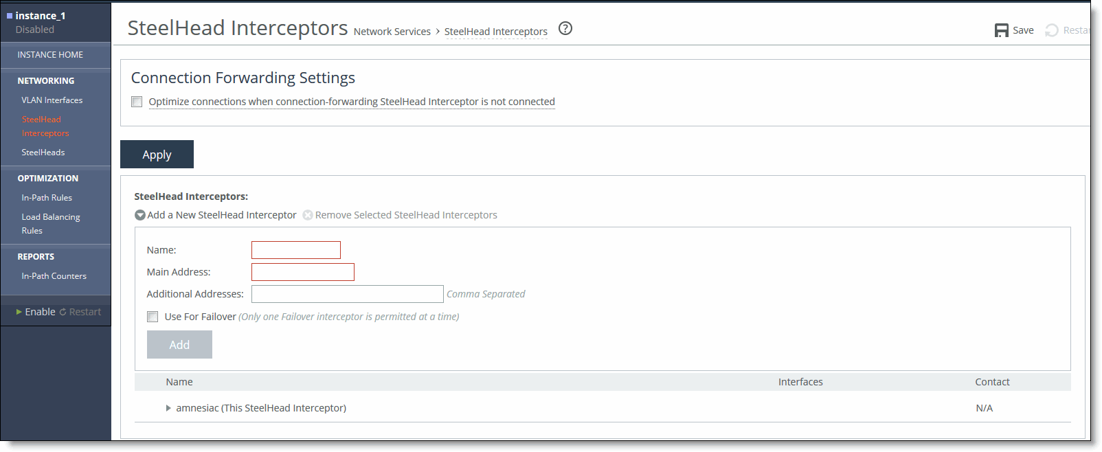
• VLAN segregation mode - Interceptors are configured on a per-instance basis. From the instance dashboard for a given instance, choose SteelHead Interceptors under the Networking section of the navigation bar.
Figure: SteelHead Interceptors Page (VLAN Segregation Mode)
2. Under Connection Forwarding Settings, complete the configuration as described in this table.
Control | Description |
Optimize Connections When Connection- Forwarding SteelHead Interceptor is Not Connected | If this appliance is configured to communicate with another SteelHead Interceptor in parallel, select this option if you want to enable allow failure mode on this appliance. The allow failure feature causes the appliance to continue to optimize new connections if connection to the cluster SteelHead Interceptor is lost. By default, the allow failure option is disabled, which means that the appliance stops attempting to optimize new connections if connection to the cluster SteelHead Interceptor is lost. Note: To enable the allow failure feature, you must select the allow failure option on all SteelHead Interceptors on the parallel links, and you must select the allow failure option on all SteelHeads that point to these SteelHead Interceptors. Note: Use the allow failure feature when you can guarantee that the traffic will be rerouted across SteelHead Interceptors that are available to process traffic. To make this guarantee, enable the fail-to-block failure condition. For more information about this failure condition, see Configuring In-Path Interfaces. |
Use Multiple Interfaces to Communicate with SteelHead Interceptors | If this appliance is to communicate with other SteelHead Interceptors on multiple interfaces, select this option to enable multiple interface support on this appliance. This option prevents loss of reachability between this SteelHead Interceptor and the other failover or cluster Interceptors that communicate with this appliance. Note: When you add this SteelHead Interceptor to the Interceptor-to-Interceptor communication list on other appliances in the set, Riverbed recommends that you specify the IP addresses of all enabled in-path interfaces on this appliance. |
Communicate with SteelHead Interceptors Using This Interface (standard mode only) | If this appliance is not to communicate with other SteelHead Interceptors on multiple interfaces, you must select one enabled in-path interface for Interceptor-to-Interceptor communication. This requirement applies whether the appliance is deployed as a failover or cluster Interceptor, or if the appliance is deployed is a single SteelHead Interceptor that does not communicate with other SteelHead Interceptors. Select this option to enable the Interface drop-down list. |
Interface (standard mode only) | Select from this drop-down list the enabled in-path interface that this appliance is to use for Interceptor-to-Interceptor communication. The inpath0_0 interface is selected by default, even if that logical interface is not enabled. For information about enabling an in-path interface on a SteelHead Interceptor, see Configuring In-Path Interfaces. Note: When you add this SteelHead Interceptor to the Interceptor communication list on the other SteelHead Interceptor or appliance with which it communicates, you enter the IP address of this interface in the Main Address field. |
Note: When the SteelHead Interceptor is running in VLAN segregation mode, the radio buttons labeled Use Multiple Interfaces to Communicate with Interceptors and Communicate with Interceptors Using This Interface and the drop-down list for selecting the in-path interface do not appear in the Interceptors page. This is because, by definition, VLAN segregation mode requires the use of multiple interfaces. These are configured on the Networking > VLAN Interfaces page of the instance dashboard. See
Adding or Removing a VLAN Tag to an Instance for more information.
3. Click Apply to apply the change.
4. Click Save to save your changes to the running configuration.
5. Under SteelHead Interceptors, add all local SteelHead Interceptors to the SteelHead Interceptor communication list using the controls as described in this table.
Control | Description |
Add a New SteelHead Interceptor | Displays the controls for adding a local SteelHead Interceptor to the Interceptor communication list on the current configuration. If you are configuring a failover Interceptor, add the other failover Interceptor. If you are configuring a cluster Interceptor, add all of the other SteelHead Interceptors in that cluster. |
Name | Specify a name for the local SteelHead Interceptor that you are adding. |
Main Address | Specify the IP address of the local SteelHead Interceptor’s in-path interface that is configured to be used for Interceptor-to-Interceptor communication. Use the following format: X.X.X.X |
Additional Addresses | If you are adding a SteelHead Interceptor on which multiple interface connection forwarding is enabled, specify additional network addresses for that SteelHead Interceptor. Note: Riverbed recommends that you specify the IP addresses of all enabled in-path interfaces on that appliance. |
Use For Failover | If you are adding a SteelHead Interceptor that is in series with the appliance you are configuring, select this option if the SteelHead Interceptor you are adding is to be the failover appliance for the appliance you are configuring. |
Add | Adds the settings to the running configuration. |
Remove Selected SteelHead Interceptors | To remove a SteelHead Interceptor from the list, select the check box next to the name and click Remove Selected Interceptors. If you remove a SteelHead Interceptor from this list, make sure that you also remove this appliance from the other SteelHead Interceptors in the set. |
6. Click Save to save your changes to the running configuration.
Configuring Interceptor-to-SteelHead Communication
You can manage a list of cluster SteelHeads (for which the SteelHead Interceptor monitors capacity and balances the load) and configure Interceptor-to-SteelHead communication in the SteelHeads page.
The SteelHead Interceptor continually monitors both TCP traffic and the available capacity of the cluster SteelHeads. When a load-balancing rule matches, the SteelHead Interceptor redirects traffic to a target SteelHead with available capacity. If a target SteelHead is unavailable or only the default rule matches, the SteelHead Interceptor redirects traffic to a cluster SteelHead that has not been reserved by a load-balancing rule.
Note: When a SteelHead is part of a SteelHead Interceptor cluster, and path selection is enabled, you must configure a path selection channel on both the SteelHead and the SteelHead Interceptor. For more information about the SteelHead, see the SteelHead Management Console User’s Guide.
To configure the SteelHeads for use with the Interceptor appliance, you must add them on this page and run a set of CLI commands from the SteelHead to enable SteelHead-to-Interceptor communication. For details, see
Configuring SteelHead-to-Interceptor Communication.
This section includes the following topics:
Configuring Connected SteelHeads
You configure the cluster SteelHeads connected to the Interceptor and Interceptor-to-SteelHead communication in the SteelHeads page.
To configure Interceptor-to-SteelHead communication
1. Display the SteelHeads page in either standard mode or VLAN segregation mode.
The location of the SteelHeads page depends on whether the SteelHead Interceptor is running in standard mode or VLAN segregation mode:
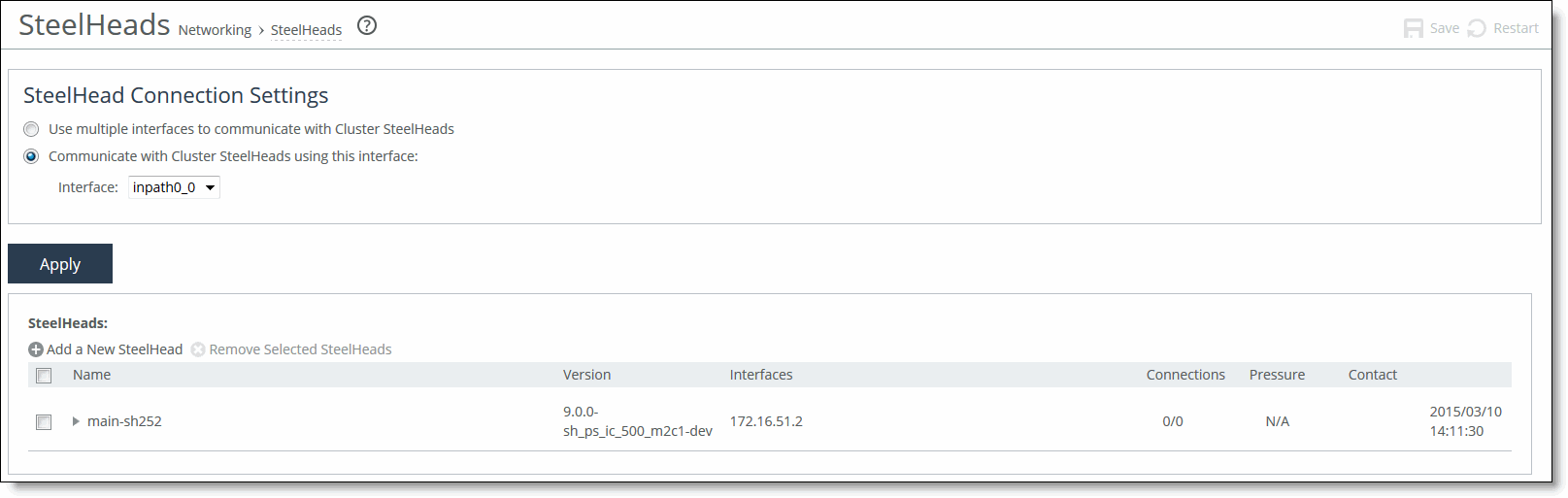
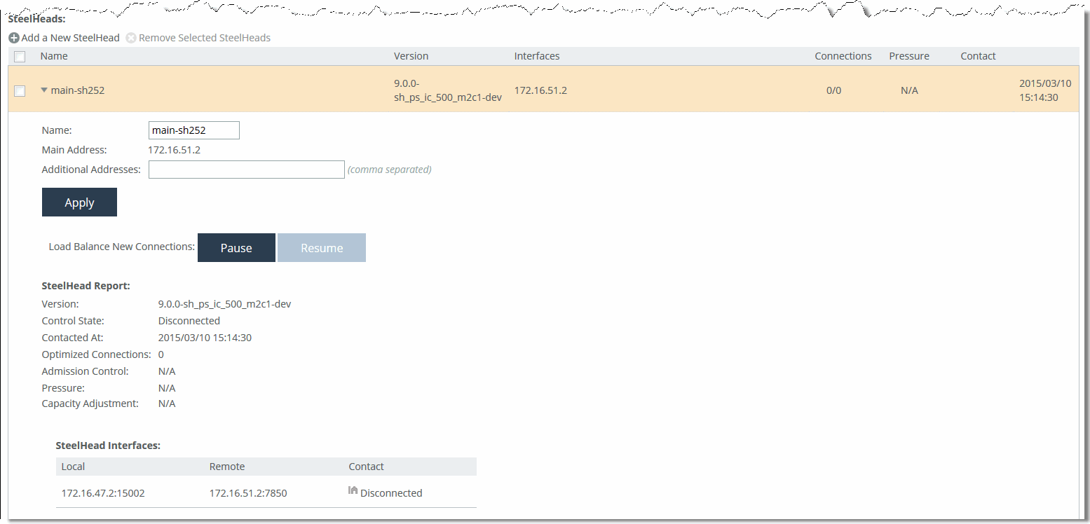
• Standard mode - Choose Networking > Network Services: SteelHeads to display the SteelHeads page.
Figure: SteelHeads Page (Standard Mode)
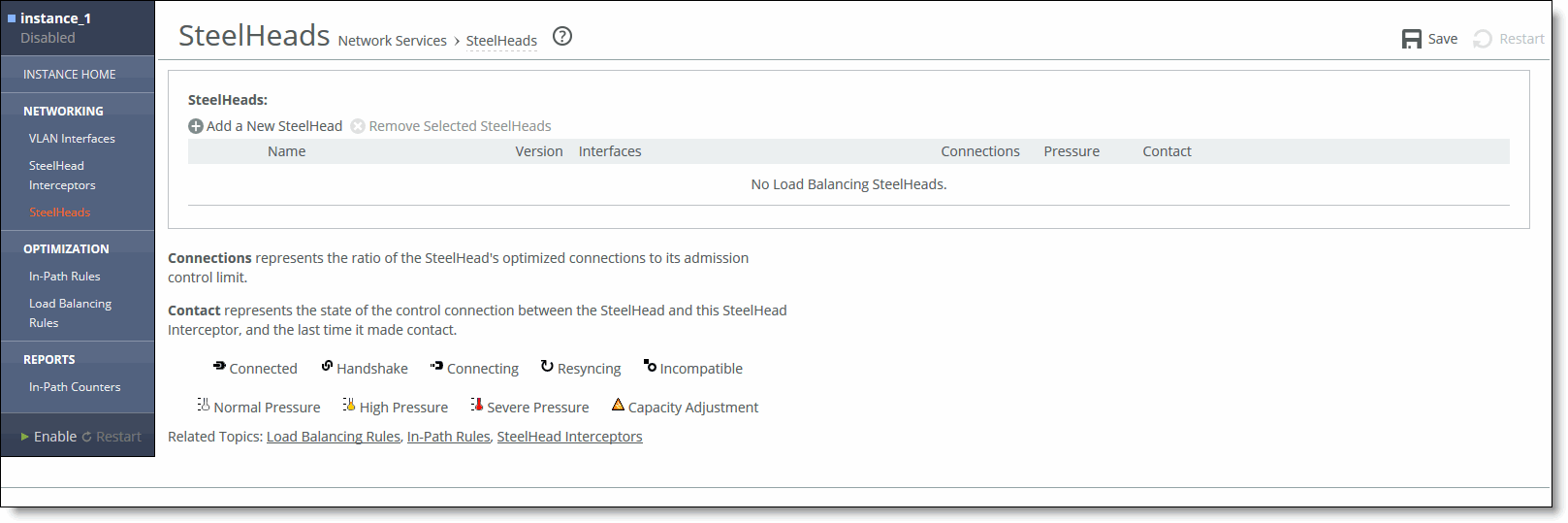
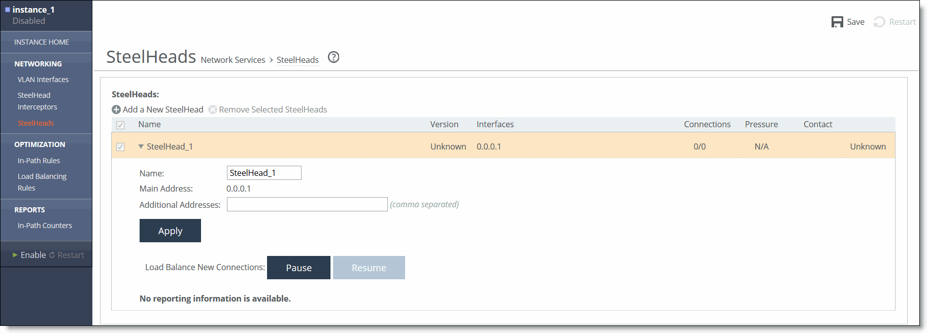
• VLAN segregation mode - SteelHeads are configured on a per-instance basis. From the instance dashboard for a given instance, choose SteelHeads under the Networking section of the navigation bar.
Figure: SteelHeads Page (VLAN Segregation Mode)
2. (Standard mode only) Optionally, under SteelHead Connection Settings, configure Multiple Interface Support as described in this table.
Control | Description |
Use Multiple Interfaces to Communicate with Cluster SteelHeads | Select this option to enable multiple interface support (MIS). MIS prevents the loss of connectivity between a SteelHead Interceptor and cluster SteelHeads and enables SteelHeads to connect using multiple WAN interfaces. If you enable multiple interface support, the following constraints apply: • 5.0x SteelHeads must be running RiOS 5.0.7 or later. • 5.5.x SteelHeads must be running RiOS 5.5.2 or later. • Load-balancing rules apply only to the main IP address. |
Communicate with Cluster SteelHeads Using This Interface | Select this option to enable selection of the interface to use for Interceptor-to-SteelHead communication. |
Interface | Use this drop-down list to select a configured in-path interface to use for Interceptor-to-SteelHead communication. The drop-down list includes only those interfaces that have been enabled and have been configured with IP addresses. For more information, see Configuring In-Path Interfaces. When selecting an interface, note the following points: • Specify the same in-path interface for Interceptor-to-SteelHead communication. • Use the same interface for communication with all SteelHeads. |
3. Click Apply to apply the change.
4. Click Save to save your changes to the running configuration.
5. To add or remove a cluster SteelHead use the controls as described in this table.
Control | Description |
Add a New SteelHead | Displays the controls to add a new SteelHead: • Name - Specify a name by which the cluster SteelHead can be identified. • Main Address - Specify the IP address for the SteelHead inpath0_0 interface. Use the following format: X.X.X.X • Additional Addresses - Optionally, specify additional IP addresses for the new cluster SteelHead. In a deployment scenario with dual-attached SteelHeads, these addresses provide a secondary route for connections to reach the target SteelHead. Note: The additional addresses are ignored if the Use Multiple Interfaces to Communicate with Cluster SteelHeads option is not selected. Use the main IP address of the SteelHead when configuring load-balancing rules. |
Remove Selected SteelHeads | To remove a SteelHead, select the check box next to the name and click Remove Selected SteelHead. Note: When you remove a SteelHead, new connections are not made until you add the SteelHead again and restart the service. If you remove the SteelHead configuration from SteelHead Interceptor A of an A-B pair, make sure to remove the SteelHead configuration from SteelHead Interceptor B. |
Add | Click to add the new SteelHead configuration to the running configuration. |
6. Click Save to save your changes to the running configuration.
Modifying an Existing SteelHead Configuration
You can modify an existing cluster SteelHead definition in the SteelHeads page.
To modify an existing a SteelHead configuration
1. Display the SteelHeads page.
The location of the SteelHeads page depends on whether the SteelHead Interceptor is running in standard mode or VLAN segregation mode:
• Standard mode - Choose Networking > Network Services: SteelHeads to display the SteelHeads page.
Figure: SteelHeads Page (Standard Mode)
• VLAN segregation mode - SteelHeads are configured on a per-instance basis. From the instance dashboard for a given instance, choose SteelHeads in the Networking section of the navigation bar.
Figure: SteelHeads Page (VLAN Segregation Mode)
2. In the list under SteelHeads, select the name of the appliance to be modified.
The listing expands to show buttons for pausing and resuming.
3. To modify the configuration, use the controls as described in this table.
Control | Description |
Name | Specify a name by which the cluster SteelHead can be identified. |
Additional Addresses | Optionally, modify the list additional IP addresses for the selected cluster SteelHead. These addresses are ignored if the Enable Multiple Interface Support check box is not selected. Note: Use the main IP address of the SteelHead when configuring load-balancing rules (or when configuring service rules if path selection is enabled). |
4. Click Apply to apply the change.
5. Click Save to save your changes to the running configuration.
Resuming or Pausing Communication with Clustered SteelHeads
You can pause and resume communication with clustered SteelHeads in the SteelHeads page.
To pause or resume communication with a SteelHead
1. Choose Networking > Network Services: SteelHeads to display the SteelHeads page.
2. Under SteelHeads, select the name of the cluster SteelHead to be paused or resumed.
The list expands to show buttons for pausing and resuming communication with the SteelHead.
3. Under Load Balance New Connections, click Pause or Resume as appropriate.
Configuring SteelHead-to-Interceptor Communication
This section describes the procedure for configuring SteelHead-to-Interceptor communication.
Each SteelHead must be configured to receive connections only through specified SteelHead Interceptors. The SteelHead communicates with the SteelHead Interceptor through SteelHead WAN ports.
Caution: The SteelHeads must not be optimizing traffic before this configuration is enabled.
Note: You must be able to provide the IP addresses of the SteelHead Interceptors that direct connections to the SteelHeads. You can obtain the IP address of an appliance by running the show interfaces command in the Riverbed command-line interface.
Note: When a SteelHead is part of a SteelHead Interceptor cluster, and path selection is enabled, you must configure a path selection channel on both the SteelHead and the SteelHead Interceptor. For more information about the SteelHead, see the SteelHead Management Console User’s Guide.
To configure SteelHead-to-Interceptor communication
1. Connect as the administrator user to the CLI for the SteelHead.
For details, see the Riverbed Command-Line Interface Reference Manual.
2. Enter configuration mode:
enable
configure terminal
3. To enable the in-path0_0 interface, enter the following command:
in-path enable
4. Enable additional in-path interfaces as necessary:
in-path interface inpath0_1 enable
5. To enable the virtual in-path support required for Interceptor deployments, enter the following command:
in-path oop enable
6. To enable SteelHead-to-Interceptor communication, enter the following command:
in-path neighbor enable
7. To enable multiple interface support, enter the following command:
in-path neighbor multi-interface enable
When using more than one in-path interface connection on the SteelHead, you must enable multiple interface support with this command. This feature is supported only on RiOS 5.0.6c and greater.
This command is optional in standard mode, but required in VLAN segregation mode.
8. For each Interceptor, at least one in-path IP address must be specified by entering the following command:
in-path neighbor name <Interceptor-name> main-ip <ip-address>
where <interceptor-name> is the hostname or IP address for the Interceptor in-path interface, and <ip‑address> is the IP address of the SteelHead Interceptor’s interface.
Note: Specify the same in-path interface you set for all Interceptor-to-SteelHead communication in
Configuring Connected SteelHeads. For example, if you set Interceptor-to-SteelHead communication on Interceptor inpath0_0, you would specify the IP address for a particular Interceptor inpath0_0 in the previous command example.
9. Supply additional addresses for the remaining in-path interfaces:
in-path neighbor name <interceptor-name> additional-ip <inpath-ip-address>
where <interceptor-name> is the hostname or IP address for the Interceptor in-path interface, and <inpath-ip-address> is the IP address of another of the SteelHead Interceptor’s inpathx_x interface.
10. Repeat the preceding step for each target SteelHead Interceptor (if more than one).
11. Repeat the entire procedure on each SteelHead in the network configuration.
Configuring WCCP
WCCP enables you to redirect traffic that is not in the direct physical path between the client and the server. To enable WCCP, the SteelHead Interceptor must join a service group at the router. A service group is a group of routers and SteelHead Interceptors that define the traffic to redirect, and the routers and SteelHead Interceptors the traffic goes through. You might use one or more service groups to redirect traffic to the SteelHeads for optimization.
WCCP configuration allows all the SteelHead Interceptor in-path interfaces to be individually configured as WCCP clients. Each configured in-path interface participates in WCCP service groups as an individual WCCP client, providing redundancy and flexibility to balance the redirected traffic load among in-path interfaces.
Enabling WCCP is optional when running in standard mode.
Note: WCCP is not supported in VLAN segregation mode and when path selection is enabled.
Note: You can also use the CLI to configure WCCP service groups. For detailed configuration information (including configuring the WCCP router), see the SteelHead Interceptor Deployment Guide.
To enable a WCCP service group
1. Choose Networking > Network Services: WCCP to display the WCCP page.
Figure: WCCP Page
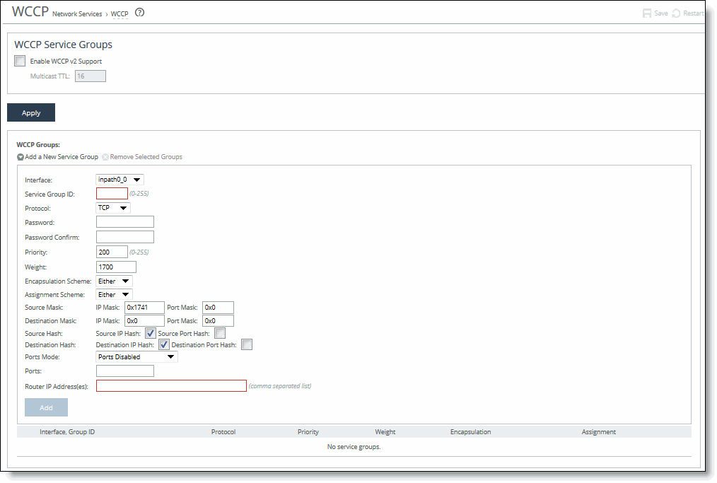
2. Under WCCP Service Groups, complete the configuration as described in this table.
Control | Description |
Enable WCCPv2 Support | Enables WCCPv2 support on all groups added to the Service Group list. |
Multicast TTL | Specify the TTL boundary for the WCCP protocol packets. The default value is 16. |
3. Click Apply to save your settings to the running configuration.
To add, modify, or remove a service group
1. Choose Networking > Network Services: WCCP to display the WCCP page.
2. Under WCCP Groups, complete the configuration as described in this table.
Control | Description |
Add a New Service Group | Displays the controls for adding a new service group. |
Interface | Select a SteelHead Interceptor interface to participate in a WCCP service group. You must include an interface with the service group ID. More than one SteelHead Interceptor in-path interface can participate in the same service group. For WCCP configuration examples, see the Riverbed Deployment Guide. If multiple SteelHead Interceptors are used in the topology, they must be configured as part of the cluster. |
Service Group ID | Enables WCCPv2 support on all groups added to the Service Group list. Specify a number from 0 to 255 to identify the service group on the router. A value of 0 specifies the standard HTTP service group. Riverbed recommends that you use WCCP service groups 61 and 62. Note: The service group ID is local to the site where WCCP is used. Note: The service group number is not sent across the WAN. |
Protocol | Select one of the following traffic protocols: • TCP • UDP • ICMP The default traffic protocol is TCP. |
Protocol | Select a traffic protocol from the drop-down list: TCP, UDP, or ICMP. The default value is TCP. |
Password/Password Confirm | Optionally, assign a password to the SteelHead Interceptor interface. This password must be the same password that is on the router. WCCP requires that all routers in a service group have the same password. Passwords are limited to eight characters. |
Priority | Specify the WCCP priority for traffic redirection. If a connection matches multiple service groups on a router, the router chooses the service group with the highest priority. The range is 0 to 255. The default value is 200. The priority value must be consistent across all SteelHead Interceptors within a particular service group. |
Weight | Specify the percentage of connections that are redirected to a particular SteelHead Interceptor interface, which is useful for traffic load balancing and failover support. The number of TCP, UDP, or ICMP connections a SteelHead Interceptor supports determines its weight. The more connections that a SteelHead Interceptor model supports, the heavier the weight of that model. You can modify the weight for each in-path interface to manually tune the proportion of traffic a SteelHead Interceptor interface receives. A higher weight redirects more traffic to that SteelHead Interceptor interface. The ratio of traffic redirected to a SteelHead Interceptor interface is equal to its weight divided by the sum of the weights of all the SteelHead Interceptor interfaces in the same service group. For example, if there are two SteelHead Interceptors in a service group and one has a weight of 100 and the other has a weight of 200, the one with the weight 100 receives one-third of the traffic and the other receives two-thirds of the traffic. However, because it is generally undesirable for an Interceptor with two WCCP in-path interfaces to receive twice the proportion of traffic, for SteelHead Interceptors with multiple in-paths connected, each of the in-path weights is divided by the number of that Interceptor's interfaces participating in the service group. For example, if there are two SteelHead Interceptors in a service group, and one has a single interface with weight 100 and the other has two interfaces, each with weight 200, the total weight will still equal 300 (100 + 200/2 + 200/2). The one with the weight 100 receives one-third of the traffic and each of the other's in-path interfaces receives one-third of the traffic. The range is 0 to 65535. The default value is 1700. For details about WCCP in a failover configuration, see Failover Support in WCCP. |
Encapsulation Scheme | Specifies the method for transmitting packets between a router or a switch and a SteelHead Interceptor interface. Select one of the following encapsulation schemes from the drop-down list: • Either - Use Layer 2 first; if Layer 2 is not supported, GRE is used. This is the default value. • GRE - Generic Routing Encapsulation. The GRE encapsulation method appends a GRE header to a packet before it is forwarded. This can cause fragmentation and imposes a capacity reduction on the router and switch, especially during the GRE packet de-encapsulation process. This capacity reduction can be too great for production deployments. • L2 - Layer-2 redirection. The Layer-2 method is generally preferred from a performance standpoint, because it requires fewer resources from the router or switch than the GRE does. The Layer-2 method modifies only the destination Ethernet address. However, not all combinations of Cisco hardware and IOS revisions support the Layer-2 method. Also, the Layer-2 method requires the absence of Layer-3 hops between the router or switch and the SteelHead Interceptor. |
Assignment Scheme | Determines which Interceptor interface in a WCCP service group the router or switch selects to redirect traffic to for each connection. The assignment scheme also determines whether the Interceptor interface or the router processes the first traffic packet. The optimal assignment scheme achieves both load balancing and failover support. Select one of the following schemes from the drop-down list: • Either - Uses Hash assignment unless the router does not support it. When the router does not support Hash, it uses Mask. This is the default setting. • Mask - Redirects traffic operations to the SteelHead Interceptors, significantly reducing the load on the redirecting router. Mask assignment processes the first packet in the router hardware, using less CPU cycles and resulting in better performance. Mask assignment supports load balancing across multiple active SteelHead Interceptors. This scheme bases load balancing decisions (for example, which SteelHead Interceptor in a service group optimizes a given new connection) on bits pulled out, or masked, from the IP address and the TCP port packet header fields. It also supports load balancing across multiple active SteelHead Interceptor interfaces in the same service group. The default mask scheme uses an IP address mask of 0x1741, which is applicable in most situations. However, you can change the IP mask by clicking the service group ID and changing the service group settings and flags. • Hash - Redirects traffic based on a hashing scheme and the Weight value of the Interceptor interface, providing load balancing and failover support. This scheme uses the CPU to process the first packet of each connection, resulting in slightly lower performance. However, this method generally achieves better load distribution. Riverbed recommends Hash assignment for most SteelHead Interceptors if the router supports it. The Cisco switches that do not support Hash assignment are the 3750, 4000, and 4500-series, among others. Your hashing scheme can be a combination of the source IP address, destination IP address, source port, or destination port. For details and best practices for using assignment schemes, see the Riverbed Deployment Guide. |
Source Mask | Specify the following: • IP Mask - Specify the service group source IP mask. The default value is 0x1741. • Port Mask - Specify the service group source port mask. |
Destination Mask | Specify the following: • IP Mask - Specify the service group destination IP mask. • Port Mask - Specify the service group destination port mask. |
Source Hash | Specify the following: • Source IP Hash - Specify that the router hash the source IP address to determine traffic to redirect. • Source Port Hash - Specify that the router hash the source port to determine traffic to redirect. |
Destination Hash | Specify the following: • Destination IP Hash - Specify that the router hash the destination IP address to determine traffic to redirect. • Destination Port Hash - Specify that the router hash the destination port to determine traffic to redirect. |
Ports Mode | Select one of the following modes from the drop-down list: • Ports Disabled - Select to disable the ports. • Use Source Ports - The router determines traffic to redirect based on source ports. • Use Destination Ports - The router determines traffic to redirect based on destination ports. |
Ports | Specify a comma-separated list of up to seven ports that the router will redirect. Use this option only after selecting either the Use Source Ports or the Use Destination Ports mode. |
Router IP Address(es) | Specify a multicast group IP address or a unicast router IP address. You can specify up to 32 routers. |
Add | Adds the service group. |
Remove Selected Groups | Select the check box next to the name and click Remove Selected Groups. |
3. Click Save to save your settings permanently.
Failover Support in WCCP
You enable single in-path failover support with WCCP groups and define the service group weight to be 0 on the backup SteelHead Interceptor. If one SteelHead Interceptor has a weight 0, but another one has a nonzero weight, the SteelHead Interceptor with weight 0 does not receive any redirected traffic. If all the SteelHead Interceptors have a weight 0, the traffic is redirected equally among them.
The best way to achieve multiple in-path failover support with WCCP groups is to use the same weight on all interfaces from a given SteelHead Interceptor for a given service group. For example, suppose you have Interceptor A and Interceptor B with two in-path interfaces each. When you configure Interceptor A with weight 100 from both inpath0_0 and inpath0_1 and Interceptor B with weight 200 from both inpath0_0 and inpath0_1, RiOS distributes traffic to Interceptor A and Interceptor B in the ratio of 1:2 as long as at least one interface is up on both SteelHead Interceptors.
In a service group, if an interface with a nonzero weight fails, its weight transfers to the weight 0 interface of the same service group.
4. For details about using the weight parameter to balance traffic loads and provide failover support in WCCP, see the SteelHead Interceptor Deployment Guide.
Setting Port Labels
You can create port labels to represent a list of ports in the Port Labels page.
You can use a port label to specify a set of ports and then apply a single in-path rule or load-balancing rule to the port label, rather than configuring rules for each port. Using port labels reduces the number of configuration rules in the system.
This section covers the following topics:
Default Port Labels
The system provides the following types of port labels by default:
• Interactive - Ports that commonly carry interactive traffic (such as Telnet, TCP ECHO, remote logging, and shell). The SteelHead and other appliances in the system automatically forward traffic carried on these ports. Use the Interactive port label in in-path rules and load-balancing rules to automatically pass through traffic on interactive ports. Port numbers include 7, 23, 37, 107, 179, 513, 514, 1494, 1718 to 1720, 2000 to 2003, 2427, 2598, 2727, 3389, 5060, 5631, 5900 to 5903, and 6000.
• RBT-Proto - Ports used by the SteelHead and other appliances in the system: 7744 (data store synchronization), 7800 to 7801 (in-path), 7810 (out-of-path), 7820 (failover), 7850 (connection forwarding), 7860 (SteelHead Interceptor), and 7870 (SteelCentral Controller for SteelHead Mobile).
• Secure - Ports that commonly carry secure traffic (SSH, HTTPS, and SMTPS). The SteelHead and other appliances in the system automatically forward traffic carried on these ports. Use the Secure port label in in-path rules and load-balancing rules to automatically pass through traffic on secure ports. Port numbers include 22, 49, 261, 443, 448, 465, 563, 585, 614, 636, 684, 695, 989, 990, 992 to 995, 1701, 1723, 2252, 2478, 2479, 2482, 2484, 2492, 2679, 2762, 2998, 3077, 3078, 3183, 3191, 3220, 3269, 3410, 3424, 3471, 3496, 3509, 3529, 3539, 3660, 3661, 3713, 3747, 3864, 3885, 3896, 3897, 3995, 4031, 5007, 5061, 7674, 9802, 11751, and 12109.
• All - When you are managing port labels, you can select all port types by selecting the check box in the table header. Specifies ports 1 to 65535.
Note: If you order rules so that traffic that is passed through, discarded, or denied is filtered first, All represents all remaining ports.
Creating Port Labels
You can create a port label to represent a list of ports in the Port Labels page.
To create a port label
1. Choose Networking > Network Services: Port Labels to display the Port Labels page.
Figure: Port Labels Page
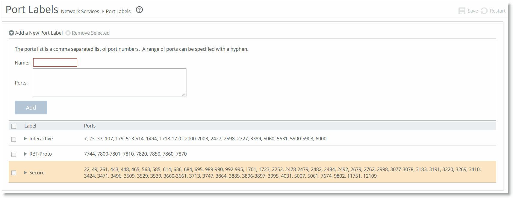
2. Complete the configuration as described in this table.
Control | Description |
Add a New Port Label | Displays the controls to add a new port label. |
Name | Specify the label name. The following rules apply: • Port labels are not case sensitive and can be any string consisting of letters, the underscore ( _ ), or the hyphen ( - ). Spaces are not allowed in port labels. • The fields in the various rule pages of the Management Console that take a physical port number also take a port label. • To avoid confusion, do not use a number for a port label. • Port labels that are used in in-path and other rules, such as QoS and peering rules, cannot be deleted. • Port label changes (that is, adding and removing ports inside a label) are applied immediately by the rules that use the changed port labels. |
Ports | Specify a comma-separated list of ports. |
Remove Selected | Select the check box next to the name and click Remove Selected. |
Add | Adds the port label. |
3. Click Save to save your changes to the running configuration.
Modifying Port Labels
You can modify ports associated with a port label by clicking on the label value in the list of port labels.
To modify ports in a port label
1. Choose Networking > Network Services: Port Labels to display the Port Labels page.
2. In the list of port labels, click the name of the port label you want to edit.
The list entry expands to display an editable list.
3. Under Ports, add or delete ports in the Editing Port Label <name> text box.
Figure: Port Labels Page
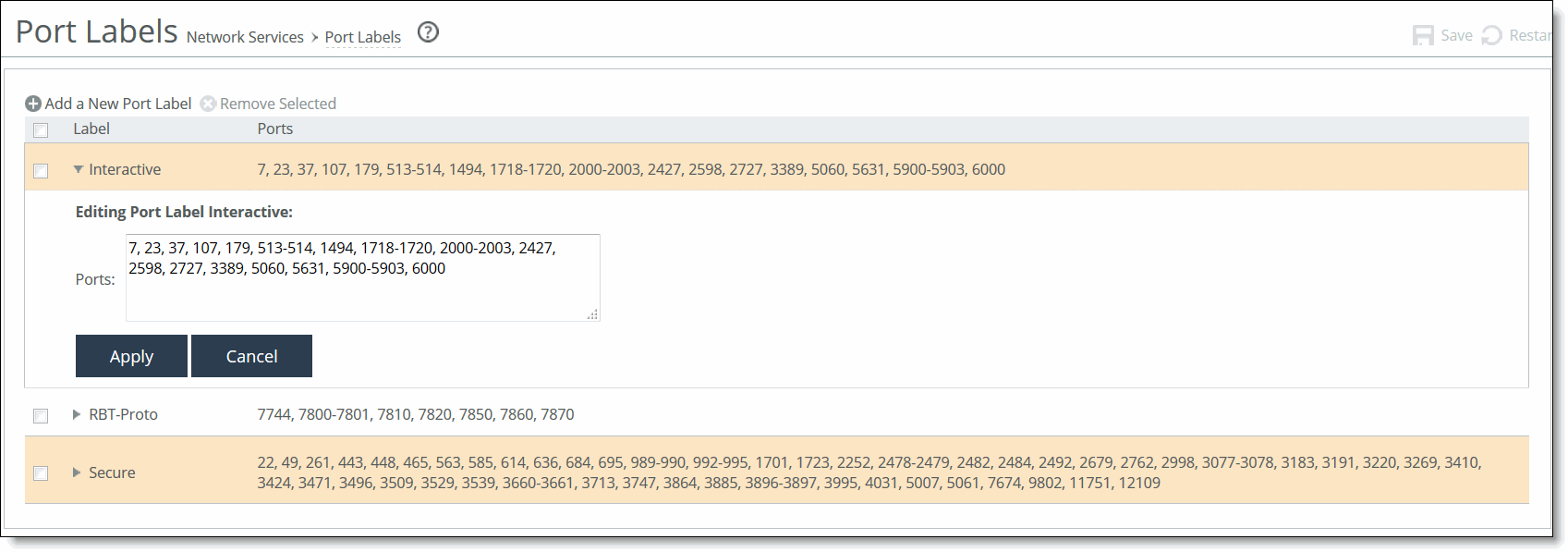
4. Click Apply to apply the modifications or click Cancel to cancel your changes.
Note: Port label changes are applied immediately by the rules that use the port labels that you have modified.
5. Click Save to save your changes to the running configuration.
Enabling Xbridge
Xbridge is a software-packet-processing enhancement supported on SteelHead Interceptors that use 10‑Gbps interfaces. When it is enabled, Xbridge provides significant line-throughput improvement for optimized and pass-through traffic for 10‑Gbps interfaces on a SteelHead Interceptor. For details about configuring Layer-4 switch, PBR, and WCCP deployments, see the SteelHead Deployment Guide.
You can enable or disable the Xbridge feature in the Xbridge page.
To enable Xbridge
1. Choose Networking> Network Services > Xbridge to display the Xbridge page.
Figure: Xbridge Page
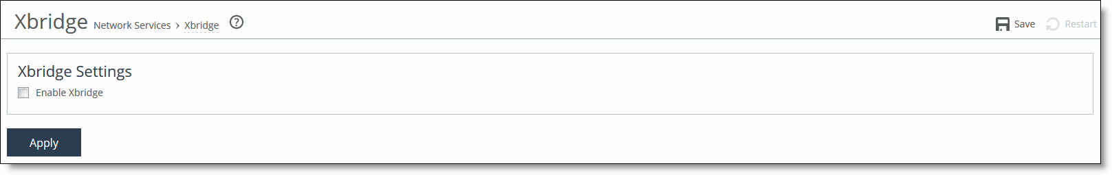
2. Under Xbridge Settings, select the Enable Xbridge check box to enable the feature.
3. Click Apply to apply the change.
4. Click Save to save your changes to the running configuration.
5. Choose Administration > Maintenance: Reboot/Shutdown, and select Reboot to restart the SteelHead Interceptor.