Figure: Alarms Page
Control | Description |
Login Message | In the text box, type a message to appear on the Login page. |
MOTD | In the text box, type a message to appear on the Dashboard page. |
Control | Description |
Admission Control | Enables an alarm when the following admission control conditions are met: • Connection Limit - Sets an alarm that triggers when the connection limit is exceeded. • Memory - Sets an alarm that triggers when the appliance memory is exceeded. • Service Limit - Sets an alarm that triggers when the number of connections receiving unoptimized service has exceeded the supported limit. |
CPU Utilization | Enables an alarm if the average and peak threshold for the CPU utilization is exceeded. When an alarm reaches the rising threshold, it is activated; when it reaches the lowest or reset threshold, it is reset. After an alarm is triggered, it is not triggered again until it has fallen below the reset threshold. By default, this alarm is enabled. Set the following: • Rising Threshold - Specify a whole number to specify a percent of CPU utilization. The default value is 100 percent. • Reset Threshold - Specify a whole number to specify a percent of CPU utilization. The default value is 95 percent. |
Disk Full | Enables an alarm if one or more of the following partitions on the disk are full: • /boot Full • /bootmgr Full • /config Full • /tmp/mnt/config Full • /var Full |
Hardware | Enables an alarm when the selected hardware conditions are met: • Fan Error - If a fan is failing or has failed and needs to be replaced. • Memory Error - If a memory error has occurred (for example, when a system memory stick fails). • Other Hardware Error - If other hardware issues occur: not enough disk, memory, CPU cores, or NIC cards to support the current configuration. • Power Supply - If an inserted power supply cord does not have power, as opposed to a power supply slot with no power supply cord inserted. • RAID - Enables an alarm and sends an email notification if the system encounters an error with the RAID array (for example, missing drives, pulled drives, drive failures, and drive rebuilds). – RAID Disk 0 Status - Checks error status of disk 0. – RAID Disk 1 Status - Checks error status of disk 1. Along with an email notification, an audible alarm might also sound. By default, this alarm is enabled. To see if a disk has failed, enter this CLI command from the system prompt: show raid diagram For drive rebuilds, if a drive is removed and then reinserted, the alarm continues to be triggered until the rebuild is complete. Rebuilding a disk drive can take 4 to 6 hours. This alarm applies only to the SteelHead Interceptor RAID Series 3000, 5000, and 6000. |
Licensing | Enables an alarm when the selected licensing conditions are met: • Appliance Unlicensed - This alarm triggers if the SteelHead Interceptor has no BASE or MSPEC license installed for its currently configured model. Note: Two additional alarms are displayed—Autolicense Critical Event and Autolicense Informational Event. Though these alarms are displayed, these alarms apply only to SteelHeads. These alarms have no impact on the SteelHead Interceptor. • License(s) Expired - This alarm triggers if one or more features have at least one license installed, but all of them are expired. • License(s) Expiring - This alarm triggers if the license for one or more features is going to expire within two weeks. |
Link Duplex | Enables an alarm and sends an email notification when an interface was not configured for half-duplex negotiation but has negotiated half-duplex mode. Half-duplex significantly limits the optimization service results. By default, this alarm is enabled. The alarm displays which interface is triggering the Link Duplex alarm. Each interface is individually listed and reported. |
Link I/O Errors | Enables an alarm and sends an email notification when the link error rate exceeds 0.1 percent while either sending or receiving packets. This threshold is based on the observation that even a small link error rate reduces TCP throughput significantly. A properly configured LAN connection experiences very few errors. The alarm clears when the rate drops below 0.05 percent. You can change the default alarm thresholds by entering the alarm error-threshold CLI command at the system prompt. For details, see the Riverbed Command-Line Interface Reference Manual. By default, this alarm is enabled. The alarm displays which interface is triggering the Link I/O Errors alarm. Each interface is individually listed and reported. |
Link State | Enables an alarm if the system has detected a link that is down. Each interface is individually listed and reported. |
Link State Propagation | Enables an alarm if the SteelHead Interceptor has detected a change in link state and propagated the change to the dynamic routing table. • Link State Propagation on All Enabled Links - Link state change propagated on all enabled links • Link State Propagation on Specific Links - Link state change propagated on specific links The SteelHead Interceptor monitors the link state of devices in its path, including routers, switches, interfaces, and in-path interfaces. |
Load Balancing Alerts | Enables an alarm when the selected load balancing conditions are met: • Load Balance Service - If the load-balancing service is not properly configured. • Oversubscription Alert - If the total capacity of the remote SteelHead is much greater than the total capacity of the local SteelHead. Note: When displayed, these alerts indicate the instances affected. |
Local Cluster Alerts | Enables an alarm when the selected local cluster conditions are met: • Local SteelHead Disconnection Alert - If a local SteelHead is disconnected from the cluster. • Local SteelHead Interceptor Disconnection Alert - If a local SteelHead Interceptor is disconnected from the cluster. • SteelHead Admission Control Alert - If a local SteelHead is under admission control. • SteelHead Capacity Alert - If a local SteelHead is near to or has reached capacity. • SteelHead Permanent Capacity Adjustment Alert - If capacity reduction has been triggered for a local SteelHead. • Version Incompatibility Alert - If version incompatibility exists among cluster appliances. Note: This alarm may also trigger if there are path selection configuration mismatches between the SteelHead and the SteelHead Interceptor. – Version Incompatibility SteelHead Alert - If version incompatibility exists among SteelHeads. – With SteelHead Interceptor 4.5.2 and later, this alert is also triggered if mixed 9350 and 9600 appliances are running in the same cluster. To correct this issue, use the CLI to configure the 9600 appliance to run in 9350 mode. – Version Incompatibility SteelHead Interceptor Alert - If version incompatibility exists among SteelHead Interceptors. |
Memory Paging | Enables an alarm when extended memory paging activity is detected. If 100 pages are swapped every couple of hours, the appliance is functioning properly. If thousands of pages are swapped every few minutes, contact Riverbed Technical Support at the follolwing link: https://support.riverbed.com This alarm is enabled by default. |
Network Bypass | Enables an alarm when the system enters bypass mode. |
Process Dump Creation Error | Enables an alarm and sends an email notification if the system detects an error while trying to create a process dump. This alarm indicates an abnormal condition where RiOS cannot collect the core file after three retries. It can be caused when the /var directory is reaching capacity or other conditions. When the alarm is raised, the directory is blacklisted. By default, this alarm is enabled. |
Suspected Scanner Traffic Alert | Triggers an alarm when a scanner is suspected. |
Temperature | Triggers an alarm when the CPU temperature exceeds the rising threshold. When the CPU returns to the reset threshold, the rising alarm is cleared. The default value for the rising threshold temperature is 70ºC; the default reset threshold temperature is 67ºC. • Critical Temperature - Enables an alarm and sends an email notification if the CPU temperature exceeds the rising threshold. When the CPU returns to the reset threshold, the critical alarm is cleared. The default value for the rising threshold temperature is 70ºC; the default reset threshold temperature is 67ºC. • Warning Temperature - Enables an alarm and sends an email notification if the CPU temperature approaches the rising threshold. When the CPU returns to the reset threshold, the warning alarm is cleared. – Rising Threshold - Specify the rising threshold (ºC). When an alarm reaches the rising threshold, it is activated. The default value is 70ºC. – Reset Threshold - Specify the reset threshold (ºC). When an alarm reaches the lowest or reset threshold, it is reset. After an alarm is triggered, it is not triggered again until it has fallen below the reset threshold. The default value is 67ºC. After the alarm triggers, it cannot trigger again until after the temperature falls below the reset threshold and then exceeds the rising threshold again |
Control | Description |
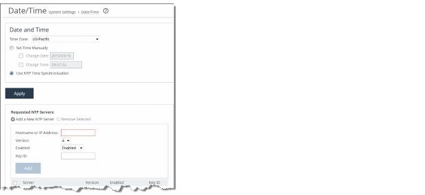
Time Zone | Select the time zone from the drop-down list. The default is US/Pacific. Note: If you change the time zone, log messages retain the old time zone until you reboot the system. |
Set Time Manually | Select this option to set the time manually. • Change Date - Specify the Change Date. Use the following format: yyyy/mm/dd • Change Time - Specify the Change Time. Use the following format: hh:mm:ss |
Use NTP Time Synchronization | Select this option to use NTP time synchronization. As a best practice, configure your own internal NTP servers; however, you can use the Riverbed-provided NTP server and public NTP servers. The hard coded IP address that is preconfigured into every SteelHead Interceptor is 208.70.196.25. This IP address and the public NTP servers are enabled by default and appear in the requested NTP server list. |
Control | Description |
Add a New NTP Server | Displays the controls to add a new NTP server. |
Hostname or IP Address | Specify the hostname or IP address for the NTP server. |
Version | Select the NTP server version from the drop-down list: 3 or 4. |
Enabled/Disabled | Select Enabled from the drop-down list to enable the connection to the NTP server. Select Disabled from the drop-down list to disable the connection to the NTP server. |
Key ID | Specify the MD5 key identifier to use to authenticate the NTP server. The valid range is 1 to 65534. The key ID must be on the trusted keys list. |
Add | Adds the NTP server to the server list. |
Remove Selected | Select the check box next to the name and click Remove Selected. |
Control | Description |
Add a New NTP Authentication Key | Displays the controls to add a new NTP authentication key. Both trusted and untrusted keys appear in the list. |
Key ID | Specify the secret MD5 key identifier for the NTP peer or server. The valid range is 1 to 65534. |
Key Type | Select the authentication key type: MD5 or SHA1. |
Secret | Specify the shared secret. You must configure the same shared secret for both the NTP server and the NTP client. The MD5 shared secret has the following characteristics: • Is limited to 16 alphanumeric characters or less, or exactly 40 hexadecimal characters. • Cannot include spaces or a pound (#) sign. • Cannot be empty. • Is case sensitive. The SHA1 shared secret has the following characteristics: • Is limited to exactly 40 hexadecimal characters. • Cannot include spaces or a pound (#) sign • Cannot be empty. • Is case sensitive. The secret appears in the key list as its MD5 or SHA1 hash value. |
Add | Adds the authentication key to the list. |
Remove Selected | Select the check box next to the name and click Remove Selected. |
Control | Description |
Enable SNMP Traps | Select to enable SNMP traps. |
System Contact | Specify the username for the SNMP contact. |
System Location | Specify the physical location of the SNMP system. |
Read-Only Community String | Specify a password-like string to identify the read-only community: for example, public. This community string overrides any VACM settings. |
Control | Description |
Add a New Trap Receiver | Displays the controls to add a new trap receiver. |
Receiver | Specify the destination IP address for the SNMP trap. |
Destination Port | Specify the destination port. |
Receiver Type | Select v1, v2c, or v3 (user-based security model) for SNMP version. |
Community | For v1 or v2c trap receivers, specify the SNMP community name; for example, public or private v3 trap receivers need a remote user with an authentication protocol, a password, and a security level. |
Remote User (v3 trap receivers only) | Specify the remote user. |
Authentication | (Appears only when you select v3). Optionally, select either Supply a Password or Supply a Key to use while authenticating users. |
Authentication Protocol | (Appears only when you select v3). Select the protocol from the drop-down list. |
Password/Password Confirm | (Appears only when you select v3). Specify and confirm the password. |
Security Level | (Appears only when you select v3). Select the security level from the drop-down list. |
Enable Receiver | Select to enable the new trap receiver. Clear to disable the receiver. |
Add | Adds the new trap receiver to the list. |
Remove Selected | Select the check box next to the name and click Remove Selected. |
Control | Description |
Add a New User | Displays the controls to add a new user. |
User Name | Specify the username. |
Authentication Protocol | Select an authentication method from the drop-down list: • MD5 - Specifies the Message-Digest 5 algorithm, a widely used cryptographic hash function with a 128-bit hash value. This is the default value. • SHA - Specifies the Secure Hash Algorithm, a set of related cryptographic hash functions. SHA is considered to be the successor to MD5. |
Authentication | Optionally, select either Supply a Password or Supply a Key to use for authenticating users. |
MD5 Key | (Appears only if you select Supply a Key). Specify the MD5 key. |
Password/Password Confirm | (Appears only if you select Supply a Password). Specify a password. The password must have a minimum of eight characters. Confirm the password in the Password Confirm text box. |
Use Privacy Option | Select the check box to enable privacy option. • Privacy Protocol - Select AES or DES from the drop-down menu. • Privacy - Select the password or key option from the drop-down menu. Depending on the option selected, you might need to specify an additional password or key value. |
Add | Adds the user. |
Remove Selected | Select the check box next to the name and click Remove Selected. |
Control | Description |
Add a New Security Name | Displays the controls to add a security name. |
Security Name | (SNMPv1 and SNMPv2c only) Specify a name to identify a requestor allowed to issue gets and sets. The security name may make changes to the View Based Access Control Model (VACM) security name configuration. Note: Traps for SNMPv1 and SNMPv2c are independent of the security name. |
Community String | Specify the password-like community string to control access. Use a combination of uppercase, lowercase, and numerical characters to reduce the chance of unauthorized access to the SteelHead Interceptor. Note: If you specify a read-only community string (located in the SNMP Basic page under SNMP Server Settings), it takes precedence over this community name and allows users to access the entire MIB tree from any source host. If this is not desired, delete the read-only community string. |
Source IP Address and Mask Bits | Specify the host IP address and mask bits to which you permit access using the security name and community string. |
Add | Adds the security name. |
Remove Selected | Select the check box next to the name and click Remove Selected. |
Control | Description |
Add a New Group | Displays the controls to add a new group |
Group Name | Specify a group name. |
Security Models and Name Pairs | Select a security model from the first drop-down list: • v1 - Select this list item to specify SNMPv1 as the security model, and then select a security name from the second drop-down list. • v2c - Select this item to specify SNMPv2 as the security model, and then select a security name from the second drop-down list • usm - Select this item to specify SNMPv3 (User-based Security Model), and then select a user from the second drop-down list. To add another Security Model and Name pair, click the plus sign (+). To remove a Security Model and Name pair, click the minus sign (-). |
Add | Adds the new groups to the list. |
Remove Selected | Removes the selected groups from the list. |
Control | Description |
Add a New View | Displays the controls to add a new view. |
View Name | Specify a descriptive view name to facilitate administration. |
Includes | Specify the object identifiers (OIDs) to include in the view, separated by commas: for example, 1.3.6.1.4.1. By default, the view excludes all OIDs. You can specify .iso or any subtree or subtree branch. You can specify an OID number or use its string form: for example, iso.org.dod.internet.private.enterprises.rbt.products.steelhead.system.model |
Excludes | Specify the OIDs to exclude in the view, separated by commas. By default, the view excludes all OIDs. |
Add | Adds the view. |
Remove Selected | Select the check box next to the name and click Remove Selected. |
Control | Description |
Add a New Access Policy | Displays the controls to add a new access policy. |
Group Name | Select a group name from the drop-down list. |
Security Level | Determines whether a single atomic message exchange is authenticated. Select one of the following from the drop-down list: • No Auth - Does not authenticate packets and does not use privacy. This is the default setting. • Auth - Authenticates packets but does not use privacy. Note: A security level applies to a group, not to an individual user. |
Read View | Select a view from the drop-down list. |
Add | Adds the policy to the policy list. |
Remove Selected | Select the check box next to the name and click Remove Selected. |

Control | Description |
SMTP Server | Specify a valid SMTP server. External DNS and external access for SMTP traffic is required for this feature to function. |
SMTP Port | Specify the port in the SMTP server. |
Report Events via Email | Select this option to report events using email. Specify a space-separated list of email addresses to which to send notification messages. To complete SNMP settings, see Configuring SNMP Basic Settings. |
Report Failures via Email | Select this option to report serious failures, such as system crashes, using email. Specify a space-separated list of email addresses to which to send notification messages. |
Override Default Sender’s Email | Select this option to specify a sender email address instead of the default “do-not-reply” sender email address. |
Report Failures to Technical Support | Select this option to report serious failures, such as system crashes, to Riverbed Technical Support. Riverbed recommends that you activate this feature so that problems are promptly corrected. |
Control | Description |
Minimum Severity | Select the minimum severity level for the system log messages. The log contains all messages with this severity level or higher. Select one of the following levels from the drop-down list: • Emergency - Emergency, the system is unusable. • Alert - Action must be taken immediately. • Critical - Conditions that affect the functionality of the SteelHead. • Error - Conditions that probably affect the functionality of the SteelHead. • Warning - Conditions that could affect the functionality of the SteelHead, such as authentication failures. • Notice - Normal but significant conditions, such as a configuration change. • Info - Informational messages that provide general information about system operations. Note: This control applies to the system log only. It does not apply to the user log. |
Maximum Number of Log Files | Specify the maximum number of logs to store. The default value is 10. |
Lines Per Log Page | Specify the number of lines per log page. The default value is 100. |
Rotate Based On | Select one of the following rotation options: • Time - Select Day, Week, or Month from the drop-down list. • Disk Space - Specify how much disk space, in megabytes, the log uses before it rotates. The default value is 16 MB. Note: The log file size is checked at ten-minute intervals. If there is an unusually large amount of logging activity, it is possible for a log file to grow larger than the set disk space limit in that period of time. |

Control | Description |
Add a New Log Server | Displays the controls for configuring new log servers. |
Server IP | Specify the server IP address. |
Minimum Severity | Select the minimum severity level for the log messages. The log contains all messages with this severity level or higher. Select one of the following levels from the drop-down list: • Emergency - Emergency, the system is unusable. • Alert - Action must be taken immediately. • Critical - Conditions that affect the functionality of the SteelHead Interceptor. • Error - Conditions that probably affect the functionality of the SteelHead Interceptor. • Warning - Conditions that could affect the functionality of the SteelHead Interceptor, such as authentication failures. • Notice - Normal but significant conditions, such as a configuration change. • Info - Informational messages that provide general information about system operations. |
Add | Adds the server to the list. |
Remove Selected | Click the check box next to the name and click Remove Selected. |

Control | Description |
Add a New Process Logging Filter | Displays the controls for adding a process-level logging filter. |
Process | Select a process to include in the log from the drop-down list: • alarmd - Alarm Manager. • cmcfc - CMC Autoregistration Utility. • rgpd - CMC Connection Manager. • rgp - CMC Connector. • cli - Riverbed command-line interface. • mgmtd - Device control and management, which directs the entire device management system. It handles message passing between various management daemons, managing system configuration and general application of system configuration on the hardware underneath through the hardware abstraction layer daemon (hald). • hald - Hardware abstraction layer daemon, which handles access to the hardware. • pm - Process Manager, which handles launching of internal system daemons and keeps them up and running. • sched - Process Scheduler, which handles one-time scheduled events. • statsd - Statistics Collector, which handles queries and storage of system statistics. • wdt - Watchdog Timer, the motherboard watchdog daemon. • webasd - Web Application Process, which handles the web user interface. |
Minimum Severity | Select the minimum severity level for the log messages. The log contains all messages with this severity level or higher. Select one of the following levels from the drop-down list: • Emergency - Emergency, the system is unusable. • Alert - Action must be taken immediately. • Critical - Conditions that affect the functionality of the SteelHead Interceptor. • Error - Conditions that probably affect the functionality of the SteelHead Interceptor. • Warning - Conditions that could affect the functionality of the SteelHead Interceptor, such authentication failures. • Notice - Normal but significant conditions, such as a configuration change. • Info - Informational messages that provide general information about system operations. |
Add | Adds the filter to the list. The process now logs at the selected severity and higher level. |
Remove Selected | Select the check box next to the name and click Remove Selected to remove the filter. |

Control | Description |
Change Password | Allows you to add or change your log in password. |
New Password/Confirm New Password | Specify a password in the text box. Retype the password in the Confirm New Password text box. |
Old Password | (Appears when password policy is enabled and the Minimum Character Difference Between Passwords value is greater than 0). Nonadministrators must specify the old password. Administrators are never required to enter an old password when changing an account password. |

Control | Description |
Current Configuration: <configuration name> | View Running Config - Displays the running configuration settings in a new browser window. Save - Saves settings that have been applied to the running configuration. Revert - Reverts your settings to the running configuration. |
Save Current Configuration | Specify a new filename to save settings that have been applied to the running configuration as a new file, and then click Save As. |
Control | Description |
Import a New Configuration | Displays the controls to import a configuration from another appliance. |
IP/Hostname | Specify the IP address or hostname of the SteelHead Interceptor from which you want to import the configuration. |
Remote Admin Password | Specify the administrator password for the remote SteelHead Interceptor. |
Remote Config Name | Specify the name of the configuration you want to import from the remote SteelHead Interceptor. |
New Config Name | Specify a new, local configuration name. |
Import Shared Data Only | Takes a subset of the configuration settings from the imported configuration and combines them with the current configuration to create a new configuration. Import shared data is enabled by default. |
Import | Select to start the import process. |
Add | When the Import Shared Data Only check box is selected, activates the imported configuration and makes it the current configuration. This is the default. When the Import Shared Data Only check box is not selected, adds the imported configuration to the Configuration list. It does not become the active configuration until you select it from the list and click Activate. |
Remove Selected | Select the check box next to the name and click Remove Selected. |
Change Active Configuration | Select the configuration to activate from the drop-down list. |