QoS Configuration Examples
This chapter provides examples of QoS configurations. This chapter includes the following sections:
For general QoS information, see
QoS Configuration and Integration.
For a QoS and Citrix configuration example, see the
SteelHead Deployment Guide - Protocols. For a QoS and SSL common name matching example, see
Overview of Application Flow Engine.
Configuring QoS Using Best Practices
This section describes an example network and the basic steps for configuring Riverbed QoS using the given specifications. This section includes the following topics:
For more information on best practices, see
QoS Enforcement Best Practices.
Example QoS Scenario
This scenario is the basis for the configuration described in
Configuring QoS on the Data Center SteelHead.
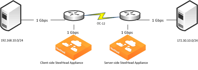
Figure: SteelHead Configuration Example shows a simple hub and spoke setup. The San Francisco data center provides the services for the remote sites and it has a connection to the internet for browsing and MS Office 365 applications.
Figure: SteelHead Configuration Example
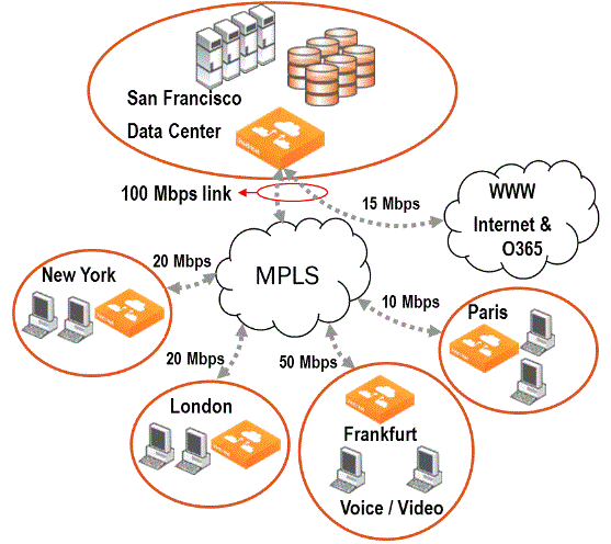
The overall goal for implementing QoS is to protect VoIP traffic from all other traffic and to protect MS Office 365 traffic from internet browsing in the data center.
The data center:
• hosts telephony services using the RTP protocol for voice.
• hosts all other services that do not need special shaping or prioritization.
• uses a SteelHead that:
– is deployed physically in-path.
– has an uplink on its in-path0_0 interface with 100 Mbps of bandwidth to the MPLS network.
– serves the four remote branch offices—New York, London, Frankfurt, and Paris—which all connect to the MPLS network.
– has an uplink on in-path0_1 to the internet with a bandwidth of 15 Mbps for browsing and access to MS Office 365.
• has the following QoS goals for outbound traffic:
– for the New York, London, and Paris sites, VoIP (using RTP) traffic is prioritized and guaranteed 20% of the sites bandwidth.
– for the Frankfurt site, 30% of the sites bandwidth is guaranteed for a video conferencing system. Of these 30%, one-third of the bandwidth is guaranteed for voice and two-thirds of the bandwidth for video. The video conferencing system uses the RTP-Voice and RTP-Video protocol.
• has the following goal for inbound traffic:
– guarantee the same bandwidth for incoming VoIP calls (using RTP) from the remote sites as for outgoing VoIP calls.
– protect MS Office 365 traffic from ordinary internet browsing traffic in the data center.
Branch offices have:
• a 20-Mbps link to the MPLS network for New York and London each.
• a 10-Mbps link to the MPLS network for Paris
• a 50-Mbps link to the MPLS network for Frankfurt.
Frankfurt has a video conferencing system installed and wants to guarantee 15Mbps of bandwidth for it. Of the 15 Mbps, 5 are guaranteed for voice and 10 for video.
• SteelHeads that are deployed physically in-path.
Figure: Graphical Representation of the Goal for QoS Implementation shows a graphical representation of the goal for implementing QoS results with the following site and profile structure.
Figure: Graphical Representation of the Goal for QoS Implementation
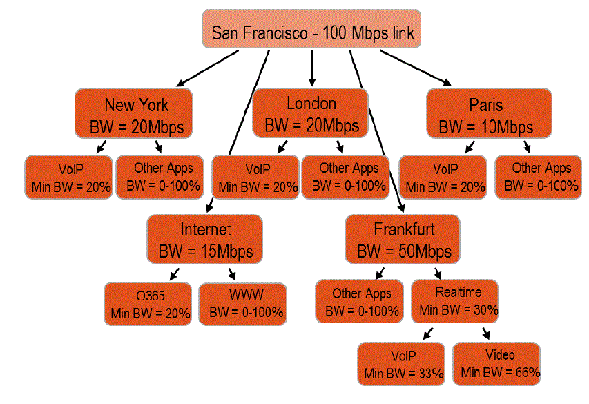
From the point of view of the San Francisco data center, you can use this site and profile structure for outbound and inbound QoS.
Configuring QoS on the Data Center SteelHead
This section describes the overall workflow to configure QoS on the data center SteelHead. This example does not require QoS configuration of the SteelHeads in the branch offices.
The workflow is as follows:
1. Configure applications, if necessary.
2. Configure QoS profiles for the sites for inbound and outbound traffic.
3. Configure the topology and assign the QoS profiles to the sites.
4. Enable QoS.
Configuring Applications
Applications must be known to the SteelHead so that you can configure QoS rules. You must configure or verify application definitions as the first step when configuring QoS. Configuring applications simplifies the workflow, so you do not have to jump between configuration pages.
For more information about applications, see
Application Definitions.
The example QoS scenario has the following important applications:
• RTP-Voice
• RTP-Video
• Office 365
To be able to protect these applications from other traffic, you need to ensure that the SteelHead can recognize them so you can use them to set up a QoS rule in the QoS profile later.
To verify that an application is known to the SteelHead
1. Choose Networking > App Definitions: Applications.
2. Select Add.
3. In the New Application screen, specify the first letters of the application name you want to verify into the Application Layer Protocol field.
Figure: New Application
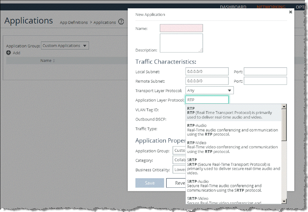
4. Check for Office 365.
Figure: MS-Office-365 in AFE
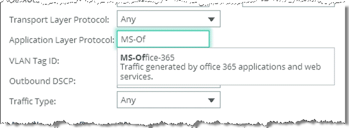
So for the example QoS scenario, you do not need to configure a new application, but you can rely on the AFE. When you configure a real-life QoS environment, you will most likely make use of the Application Groups.
You can use this process to create new applications, if the application you want is not in the AFE.
To learn about Application Groups and creating new applications, see
Applications.
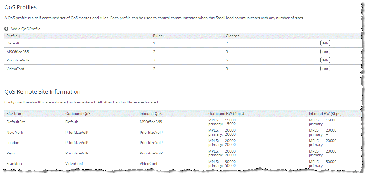
Creating QoS Profiles
The QoS profile is the building block that contains the QoS classes and rules for traffic going to a site. You can assign a single QoS profile to many sites and you can use it to configure inbound and outbound QoS.
For more information about profiles, see
QoS Profiles.
For the example QoS scenario, you must create three QoS profiles. One profile for the sites New York, London and Paris, one for Frankfurt, and one for incoming MS Office 365 traffic that must be protected from incoming internet browsing traffic.
To create a QoS Profile for New York, London, and Paris
1. Choose Networking >Network Services: Quality of Service.
2. Select Add a QoS Profile.
The New Profile box opens and prompts for a profile name.
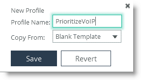
3. If you already had created a profile earlier, you are able to use this profile as a template for a new profile. For this example, choose Blank Template, enter a name (PrioritizeVoIP) and click
Save (
Figure: Add a Profile Name).
Figure: Add a Profile Name
The new profile appears in the QoS profiles table.
4. Click Edit.
The empty profile opens.
You must configure the class. An empty profile always starts with the Root class, which represents the bandwidth of the uplink of a site.
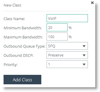
5. In the QoS classes section of the page, click Edit, and then select Add Class.
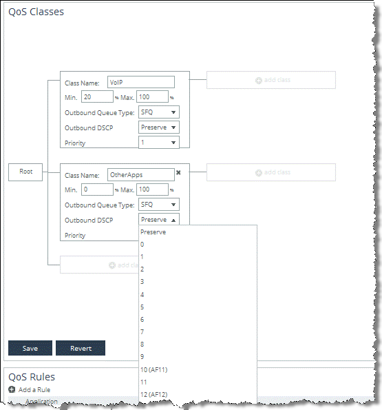
6. Configure a class for the VoIP traffic. Give the class a name, set the minimum bandwidth to 20%, and choose priority 1 for real-time traffic.
Figure: Add a VoIP Class
8. Create the class for other traffic. Click Add Class, give the class a name, and set the priority to 4, which is Normal priority.
Figure: Add OtherApps Class
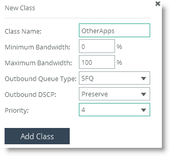
Figure: QoS Configured Classes
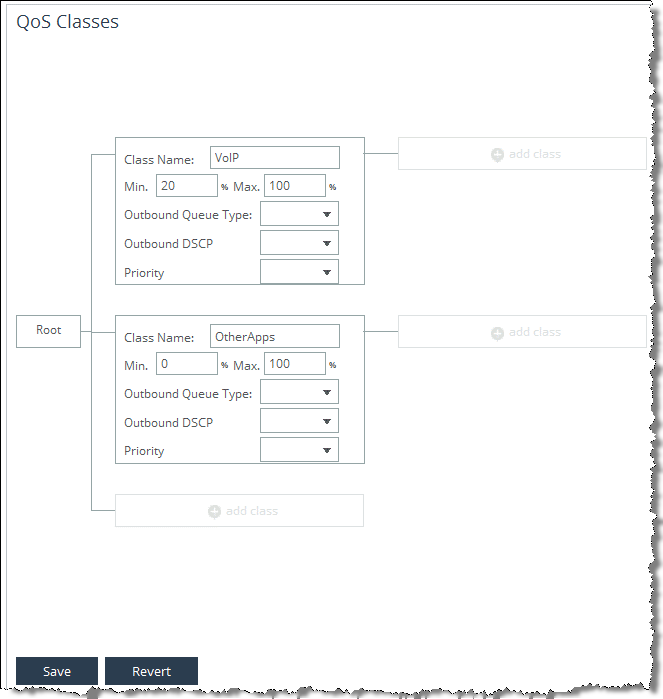
10. Click Save.
Next, configure the QoS rules to direct the traffic into the classes.
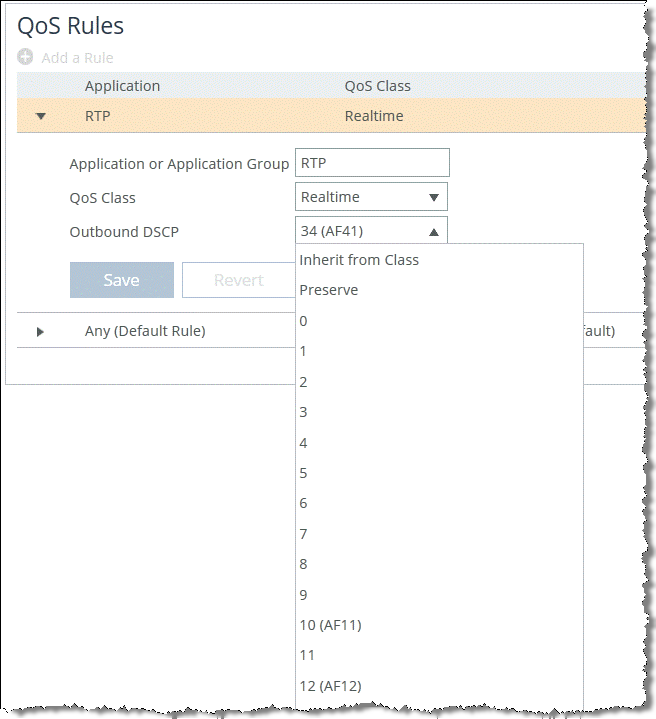
11. In the QoS Rules section, select Add a Rule.
12. RTP-Audio from the Application or Application Group drop-down menu.
Figure: Add New RTP-Audio Rule
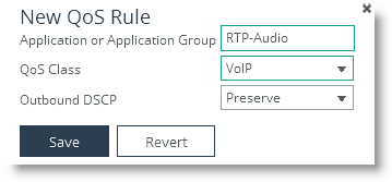
14. Click Save.
The new QoS rule is shown in the QoS Rules table.
Now you need to edit the Any or Default Rule to point it to the OtherApp class you created.
Figure: Changing the QoS Class
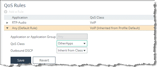
16. Click Save.
The QoS Profile for New York, London, and Paris is now ready to use.
The Frankfurt site requires an additional level of hierarchy to accommodate for the video conferencing traffic and also has different bandwidth requirements. However, in this example, you can use the existing PrioritizeVoIP profile as a template and modified accordingly.
To create a QoS Profile for Frankfurt
1. To edit the existing PrioritizeVoIP profile, choose Networking > Network Services: Quality of Service.
2. In the QoS Profiles section of the page, select Add a QoS Profile.
The VideoConf profile appears in the QoS Profiles table.
Figure: Creating a Profile from Existing Profile
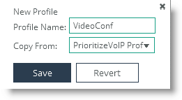
4. Click Save.
The VideoConf profile appears in the QoS Profiles table.
5. Click Edit.
6. Edit the QoS classes of the profile. Change the:
• name of the VoIP class to VideoConference.
• minimum bandwidth to 30% according to the example QoS scenario.
7. Before you can add a level of hierarchy to this class, edit all rules that point to it to point to the default class or delete the rule. A parent class cannot have a QoS rule assigned to it.
Next, add a class for the voice part of the video conferencing system.
8. Click Add Class, which is connected to the VideoConference class.
9. Enter a name (Voice) for the class, set the minimum bandwidth to 33% according to the example QoS scenario, and select priority 1, which is real-time (
Figure: Add Voice Class).
Figure: Add Voice Class
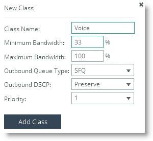
10. Click Add Class.
11. Repeat the above steps to configure a class for the video part of the video conferencing system.
Choose Video for the name of the class and configure the Priority to 2, which is interactive. You do not have to set a minimum bandwidth, because you already guaranteed bandwidth to the voice part.
Figure: Finished QoS Class Configuration
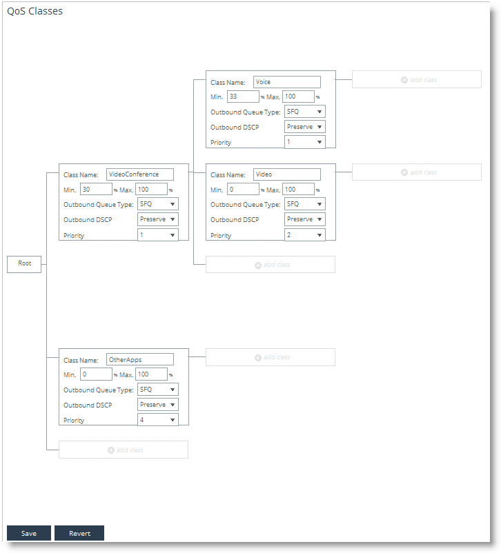
12. Click Save.
13. Configure the QoS rules to direct the traffic into the classes.
• Configure one rule for RTP-Audio to point to the Voice class.
• Configure one rule for RTP-Video to point to the Video class.
Figure: Finished QoS Rules Table
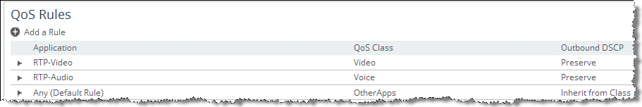
The QoS profile for Frankfurt is now ready to use.
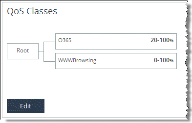
Setting up a QoS profile is the same for inbound and outbound QoS. Internet traffic usually generates more incoming than outgoing traffic. That is why in this example QoS scenario, the incoming MS Office 365 traffic must be protected from incoming internet browsing traffic.
Note: This procedure assumes you have read the beginning of this section and know the intermediary steps.
To create a QoS profile and rules to protect MS Office 365
1. Create a class for the MS Office 365 traffic.
2. Set the minimum bandwidth to 20% and configure the priority to 3, which is business critical.
3. Create a class for all other internet traffic and set its priority to 5, which is low priority.
Figure: QoS Class Setting for MS Office 365
4. To configure the QoS rules, select Add a Rule and select MS-Office-365.
5. Select O365 as QoS class.
6. Click Save.
7. Point the default rule to the WWWBrowsing class.
Figure: Configured QoS Rules Table
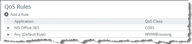
The QoS profiles needed for the example QoS scenario are now configured.
Configuring Topology
The topology provides the SteelHead with a view onto the network it is connected to. The topology consists of the network, the sites, and the uplinks to the network for the sites. Additionally, the QoS profiles are linked to the sites.
For more information about topology, see
Topology.
To configure the topology, choose Networking > Topology: Sites & networks. The My WAN network is configured by default.
To configure networks
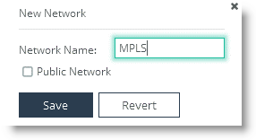
1. Select Add a Network.
2. According to the example, specify MPLS as the name in the New Network box (
Figure: Network Name).
The Public Network check box is used with the secure transport feature for SCC. For more details, see the SteelCentral Controller for SteelHead Deployment Guide.
Figure: Network Name
3. Click Save.
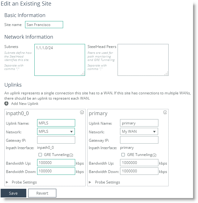
To configure the Local site
1. Click Edit for the Local (Local) site.
The local site is the physical location of the SteelHead you are connected to.
2. According to the example, rename the site San Francisco.
3. Specify the local subnets into the Subnets field.
4. According to this example (because the uplink connects to the MPLS network), select MPLS as uplink inpath0_0 from the name drop-down menu.
The configuration options for SteelHead Peers, Gateway IP, GRE Tunneling, and Probe are only used for the path selection feature and not needed for QoS.
You can leave the default values in the primary uplink because you do not need to configure it for QoS. Because the local site is the site in which the SteelHead you are configuring is physically located, you cannot assign any QoS profiles to the local site.
Figure: MPLS Network
6. Click Save.
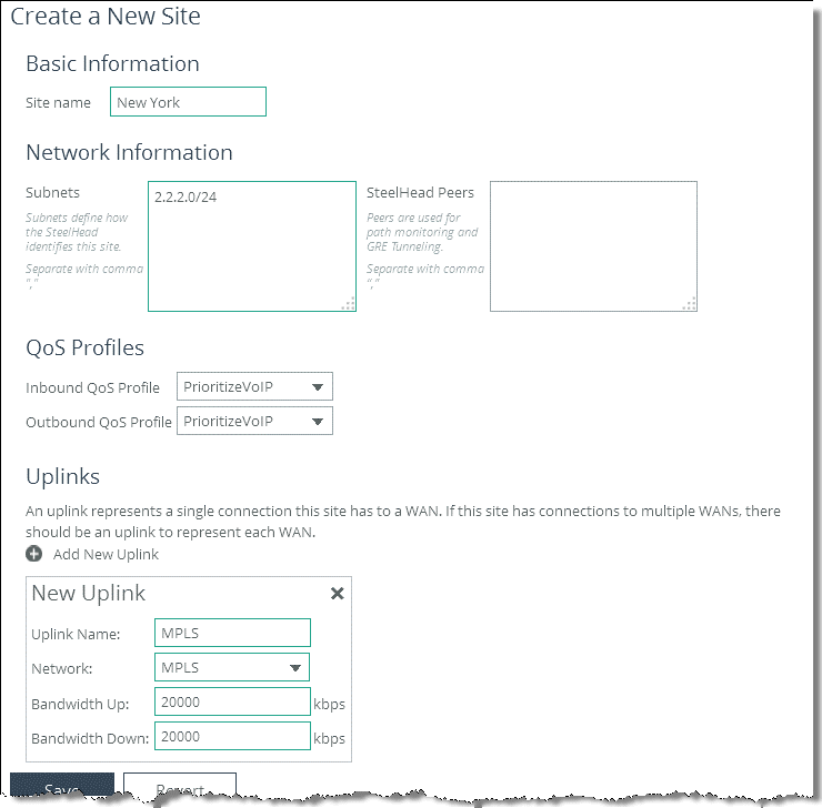
To configure the remote sites
1. Select Add a Site.
2. According to the example, specify New York.
3. Specify the local subnets.
4. Assign the QoS profiles by selecting PrioritizeVoIP as inbound as well as outbound QoS profile.
5. Select Add New Uplink.
6. Select MPLS from the Network drop-down box and enter the up and down bandwidth.
According to the example QoS scenario, the bandwidth for the New York site is 20 Mbps for both.
Figure: Site Configuration
7. Click Save.
8. Repeat the same process for the London and Paris sites.
According to the example QoS scenario, the sites New York, London and Paris, can all use the PrioritizeVoIP QoS profile. Remember to configure the correct up and down bandwidth for the Paris site.
9. Configure the Frankfurt site.
Use the same procedure as above. The differences are the bandwidth and the QoS profile. Select 50 Mbps as up and down bandwidth and assign the VideoConf profile as inbound and outbound QoS profile.
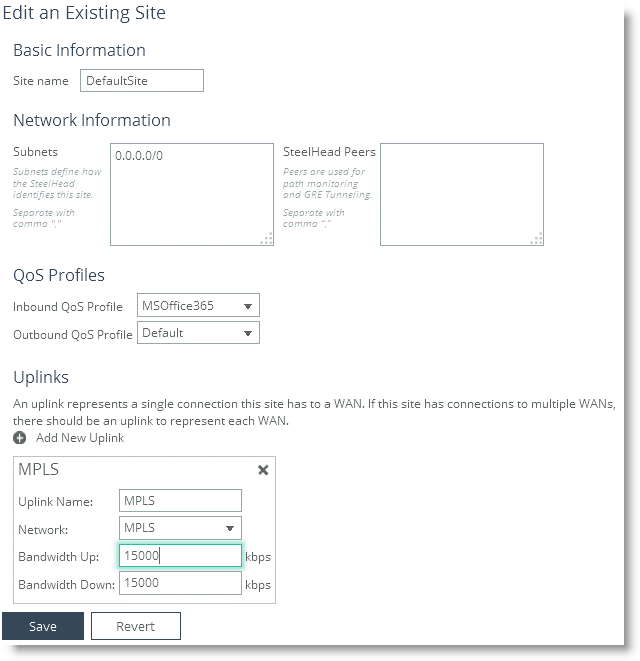
10. Configure the DefaultSite.
According to the example QoS scenario, you want to configure MS Office 365 traffic to be protected from internet browsing. Internet traffic in general is not bound to a specific site, which is why you need to use the default site.
• Select the MSOffice365 profile as inbound QoS profile.
• Select Add New Uplink to the default site.
• Specify a name.
• Connect the uplink to the MPLS network.
• Configure the up and down bandwidth to 15 Mbps.
Figure: Default Site Configuration
11. Click Save.
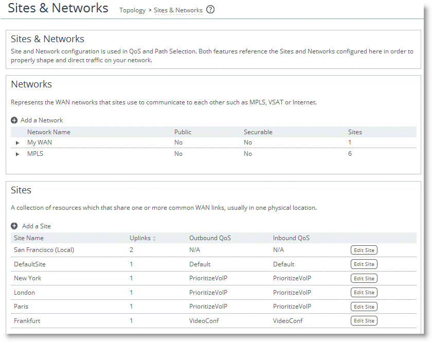
Your final Sites & Networks page looks like
Figure: Final Sites & Networks Page.
Figure: Final Sites & Networks Page
Enabling QoS on the SteelHead
Riverbed recommends as a best practice to first configure QoS on a SteelHead and then enable QoS as the final step. This order prevents unexpected network behavior while configuring QoS. However, to correctly classify traffic, the SteelHead must detect the three-way TCP handshake of the session carrying that traffic. Therefore, when you enable QoS, existing TCP/UDP session is not classified correctly and is classified to the default class.
You must make sure to enable QoS at a time when network usage is low, or during a maintenance window.
To enable QoS
1. Choose Networking > Network Services: Quality of Service.
Figure: Enable QoS Shaping
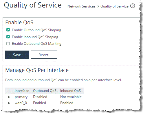
3. Click Save.
In the Manage QoS Per Interface section of the Quality of Service page, wan0_0 is enabled for inbound and outbound QoS by default.
In summary, the Networking > Network Services: Quality of Service pages shows you a summary of what you have been configuring to set up QoS on the SteelHead. You can use this page to quickly check what is configured for QoS and if it is configured correctly (
Figure: Quality of Service Page as a Summary).
Figure: Quality of Service Page as a Summary
Configuring QoS Marking on SteelHeads
You can mark incoming traffic to a LAN port of a SteelHead with a DSCP or an IP ToS value (for information about default behavior, see
QoS Marking Default Setting).
For more information about QoS marking settings, see the SteelHead Management Console User’s Guide.
Note: Prior to RiOS 7.0, the DSCP or IP TOS value on a server-side SteelHead was determined by the DSCP or IP ToS value of the client-side SteelHead. If you are running an earlier version of RiOS, see an earlier version of this guide for instructions on how to configure the DSCP or IP ToS value.
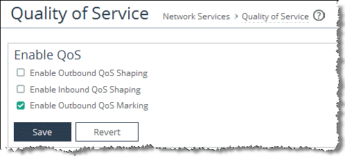
To enable QoS marking on a SteelHead
1. Choose Networking > Network Services: Quality of Service.
Figure: Enable QoS Marking
After you define the application, you can mark it with a DSCP or IP TOS value in a QoS profile. The application can either inherit the DSCP or IP TOS value from a QoS class or you can create a QoS rule to mark it with a DSCP or IP TOS value. For more information about how to define an application, see
Defining an Application.
With RiOS 9.0 and later, marking traffic with a DSCP or IP TOS value is no longer part of the application definition. If you are using a release previous to RiOS 9.0, see earlier versions of the
SteelHead Deployment Guide on the Riverbed Support site at https://support.riverbed.com.To set DSCP or IP ToS value per class in a QoS profile
1. Choose Networking > Network Services: Quality of Service.
2. Edit an existing QoS profile or select Add a Profile to create a new QoS profile.
Figure: Setting DSCP or IP ToS Value Per Class in a QoS Profile
To set DSCP or IP ToS value per application in a QoS profile
1. Choose Networking > Network Services: Quality of Service.
2. Edit an existing QoS profile or select Add a Profile to create a new QoS profile.
3. Edit an existing QoS rule or select Add a Rule to create a new QoS rule.
4. Select the application or application group to mark with a DSCP or IP TOS value.
Figure: Setting a DSCP or IP ToS value
The DSCP or IP ToS value that you define in a QoS rule of a QoS profile takes precedence over the values defined in the QoS class of the same QoS profile.
Riverbed recommends that complete the following settings:
• For QoS marking only, set the DSCP or IP ToS value in the QoS rule of a QoS profile.
• For QoS marking and traffic shaping, set the DSCP or IP ToS value in the QoS class of a QoS profile.
Configuring QoS and MX-TCP
This section describes how to configure Riverbed QoS and MX-TCP on the SteelHeads.
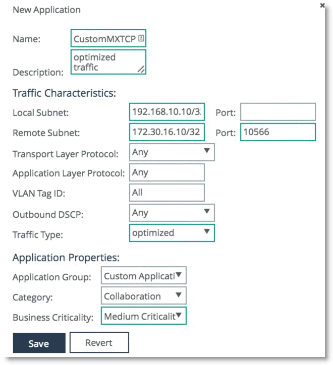
Figure: MX-TCP Example shows an example in which the client expects to have a certain application—running over port 10566—to be classified into an MX-TCP QoS class.
Figure: MX-TCP Example
For additional information about MX-TCP, see
MX-TCP and
MX-TCP Settings.
To configure QoS and MX-TCP on the client-side SteelHead
1. On the client-side SteelHead, create a custom application that is based on optimized traffic only, with header based rules, and without selecting any applications in the Application Layer Protocol field (
Figure: Custom MX-TCP Application).
Figure: Custom MX-TCP Application
2. Click Save.
3. Choose Networking > Network Services: Quality of Service.
4. Select Add a Profile.
Figure: MX-TCP QoS Profile
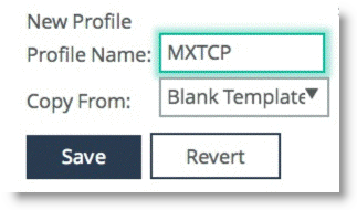
6. Click Save.
7. Click Edit on the profile you created.
8. Configure a Default class for any traffic not matching any rules.
Make sure you select MXTCP as the Outbound Queue Type. If the SteelHead has a bandwidth limit, then you must configure the minimum bandwidth within that limit. The MX-TCP class can use up to 99% of the bandwidth of the WAN class.
Figure: Configuring a Default Class
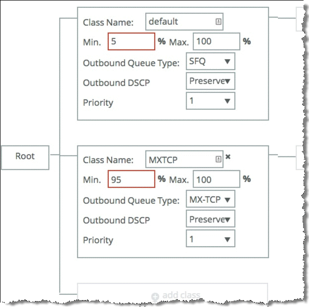
10. Click Save.
11. Select Add a Rule, and select the custom application you already created and assign it to the MXTCP class (
Figure: MX-TCP New QoS Rule).
Figure: MX-TCP New QoS Rule
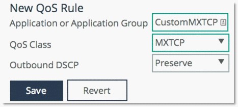
12. Click Save.
13. Assign this Profile to a site.