Configuring Hybrid Networking, QoS, and Path Selection
This chapter describes features that maximize performance of networks and hybrid networks across branch offices. Hybrid network architecture typically combines private assets such as MPLS-based WAN networks with public services such as the internet. RiOS provides application-level Quality of Service (QoS) and WAN path selection to control network consumption and prioritize critical and latency sensitive applications, while minimizing use by noncritical applications.
This chapter includes these topics:
For details about QoS and path selection, see the SteelHead Deployment Guide.
Where do I start?
Network topology and application properties form the reusable building blocks that allow you to inspect and direct network traffic using the QoS, path selection, and web proxy features. On an SCC, you can protect network traffic by reusing these building blocks with the secure transport feature. In addition, the application statistics collector in the SCC provides visibility into the throughput data for optimized and pass-through traffic flowing in and out of the SteelHeads in your network. For details, see the SteelCentral Controller for SteelHead User Guide.
Best practices for QoS configuration
This table provides the suggested workflow for configuring QoS.
Task | Notes | For detailed instructions |
1. Define applications | Choose Networking > App Definitions: Applications. Attach a business relevancy to all traffic that goes through your network. Application definitions enable you to prioritize traffic with QoS and steer traffic down a particular path with path selection. Use the preexisting default definitions to identify applications. If the application doesn’t appear in the preexisting application list, you can define a custom application. | |
2. View or modify the default QoS profile, or configure additional QoS profiles | Choose Networking > Network Services: Quality of Service to view the QoS classes that are used for the default profile. Optionally, modify the default profile by editing the classes, creating additional classes, or adding rules. The classes specify the traffic hierarchy, priority, and the minimum and maximum bandwidth the class uses for shaping. The rules can use application definitions and application groups. Optionally, create an entirely new QoS profile and attach rules to that profile. | |
3. Define a view of all available networks | Choose Networking > Topology: Sites & Networks. On a SteelHead, the network definition is simply a name: for example, MPLS. | |
4. Define sites | Choose Networking > Topology: Sites & Networks. Sites provide the SteelHead with the IP addresses of all existing subnets (including non-SteelHead sites). It’s important to define all remote subnets in the enterprise so they can be matched with the correct QoS profile. You must define local and remote sites and local gateways. You also define the default site as a catch-all for traffic that is not assigned to another site and for backhaul traffic. | |
5. Assign a QoS profile to sites | Choose Networking > Topology: Sites & Networks, click Edit Site, select an inbound and outbound QoS profile, and click Save. Select Default to use the default profile. Assign one profile per site. You can’t assign a profile to a network. | |
6. Enable QoS | Choose Networking > Network Services: Quality of Service. | |
Best practices for path selection configuration
This table provides the suggested workflow for configuring path selection.
Task | Notes | For detailed instructions |
1. Define applications | Choose Networking > App Definitions: Applications. Attach a business relevancy to all traffic that goes through your network. Use the preexisting default definitions to identify applications. If the application doesn’t appear in the preexisting application list, you can define a custom application. | |
2. Define a view of all available networks | Choose Networking > Topology: Sites & Networks. The network definition is simply a name: for example, MPLS. | |
3. Define sites | Choose Networking > Topology: Sites & Networks. Provides the SteelHead with the IP addresses of all subnets existing within a site (this applies to non-SteelHead sites as well). It’s important to define all remote subnets in the enterprise so they can be matched with the correct rules. You must define local and remote sites. The site definitions include a list of IP subnets that path selection will use to identify the site. Every subnet must be globally unique, although they can overlap. You also define the default site as a catch-all for traffic that is not assigned to another site. Specify the SteelHead peers to use for path monitoring. SteelHead peers are select distinct IP addresses you choose to poll, in order, to verify path availability. | |
4. Define uplinks that join the sites to the networks | Choose Networking > Topology: Sites & Networks. You must define the local site with the gateway IP address and the in-path interface the uplinks will use to connect to the network. On the SteelHead you are configuring, the local default gateway is the in-path interface. When you configure path selection, if the default gateway is pointing to the LAN side of the SteelHead, we recommend changing the interface to point the gateway to the WAN side of the SteelHead to avoid packet ricochet. The order of sites isn’t important because the longest prefix in the site subnet is matched first. | |
5. Enable path selection | Choose Network > Network Services: Path Selection and select Enable Path Selection. | |
6. Configure path selection rules | Path selection rules direct matching traffic onto specific uplinks. Traffic is matched by a combination of application and destination site. | |
Defining a hybrid network topology
You define the network connectivity view in the Networking > Topology: Sites & Networks page.
RiOS 9.0 and later provide a way to define a static network topology to a configuration that is shareable between SteelHeads. The network topology definition becomes a building block that simplifies SteelHead feature configuration for path selection and QoS. You define a topology once and then reuse it as needed. The topology provides the network point-of-view to all other possible sites, including each remote site’s networks and a remotely pingable IP address.
RiOS uses the topology definition to:
•share the remote site information between peers.
•determine possible remote paths for path selection.
•precompute the estimated end-to-end bandwidth for QoS, based on the remote uplinks.
We strongly recommend that you define topologies, push topology definitions, and distribute updates to an existing topology from a SteelCentral Controller for SteelHead to the SteelHead appliances, particularly with large scale deployments. For details, see the SteelCentral Controller for SteelHead Deployment Guide.
Topology properties
A network topology includes these WAN topology properties:
•Networks - Define the carrier-provided WAN connections: for example, MPLS, VSAT, or internet.
•Sites - Define the discrete physical locations on the network: for example, a branch office or data center. A site can be a single floor of an office building, a manufacturing facility, or a data center. The sites can be linked to one or more networks. The local sites use the WAN in the network definition to connect to the other sites. The default site is a catch-all site that is the only site needed to backhaul traffic.
Use sites with path selection, QoS, and secure transport features.
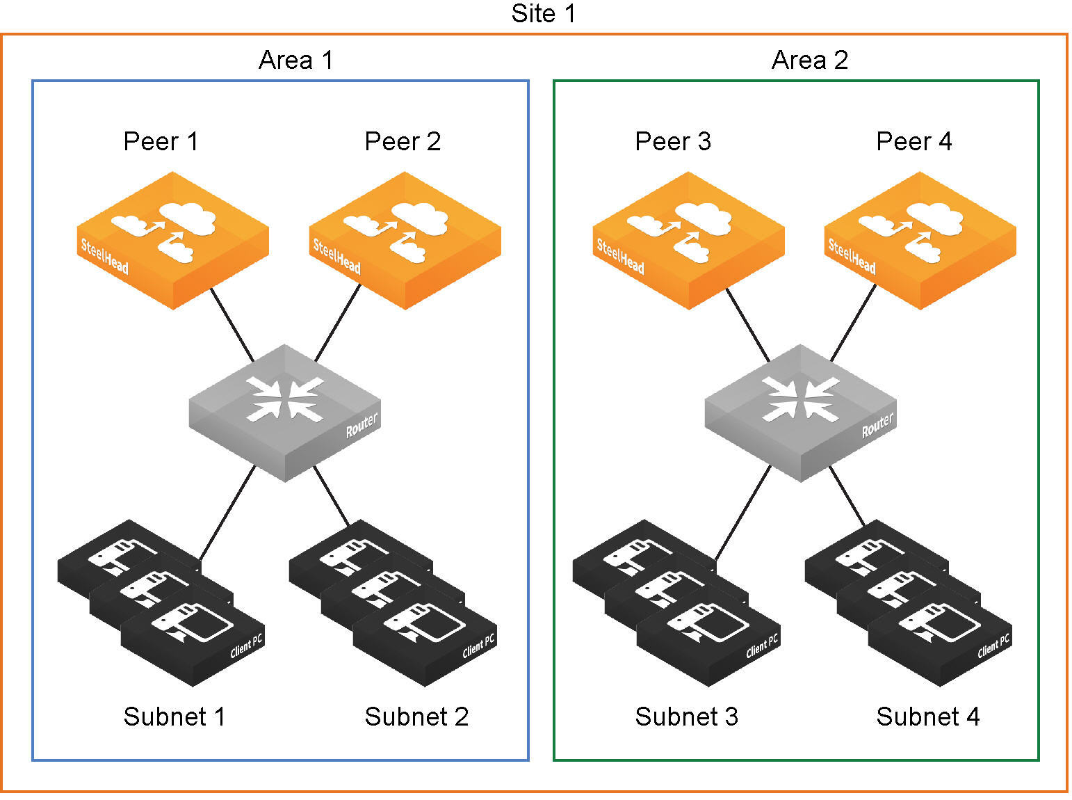
If SteelHead peers connect to subnets within a network that don’t communicate with each other, you can define an area, as shown in
Site definition divided into areas. To configure areas, use the Riverbed command-line interface.
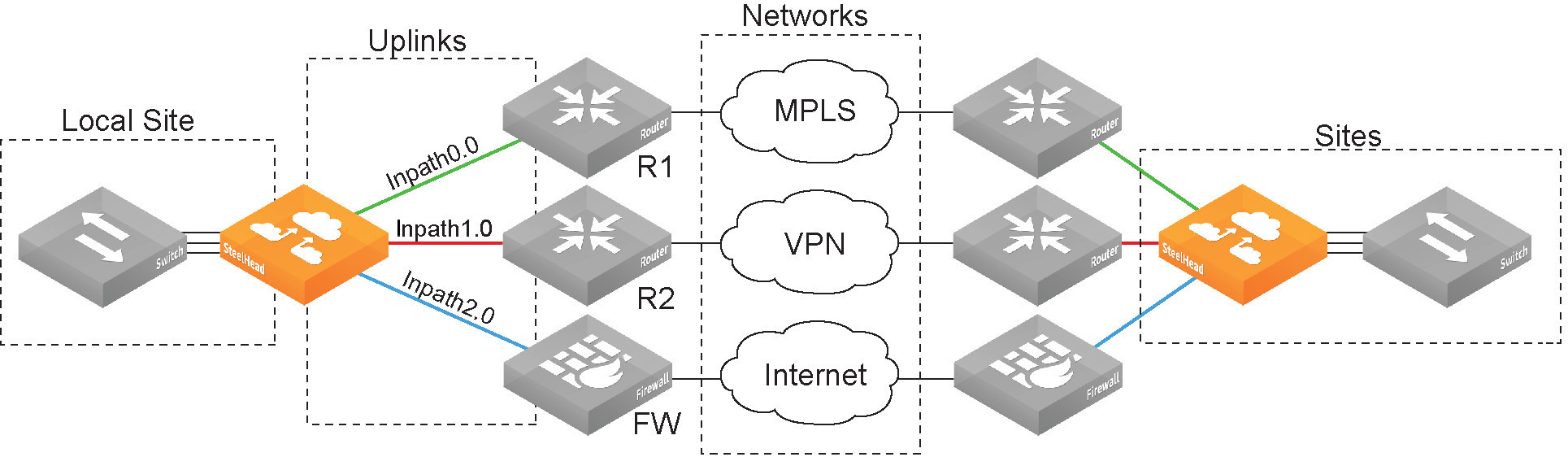
•Uplinks - Define the last network segment connecting the local site to a network. You define carrier-assigned characteristics to an uplink: for example, the upload and download bandwidth and latency. An uplink must be directly (L2) reachable by at least one SteelHead or Interceptor in the local network. An uplink doesn’t need to be a physical in-path. Path selection uses only local uplinks.
Topology overview
Site definition divided into areas
The Sites & Networks page is central to defining networks and sites, viewing sites with which a network is associated, changing or deleting sites, and assigning uplinks to a site.
Defining a network
Networks represent the WAN networks that sites use to communicate with each other, such as MLPS, VSAT, or internet.
To add a network
1. Choose Networking > Topology: Sites & Networks to display the Sites & Networks page.
Sites & Networks page
The networks appear. The default network is the network to which RiOS links the default uplinks. You can’t delete the default network.
If you aren’t using path selection, you can use the default network. To configure path selection, you can edit the network for the default uplinks: for example, Default0_0 uses MPLS, while Default0_1 uses internet.
2. Under Networks, click + Add a Network.
The New Network dialog box appears.
New Network dialog box
3. Specify the network name, for example, MPLS1.
4. Select Public Network if the network represents the internet.
You can also configure a secure network on the SCC. Secure transport uses UDP to encapsulate traffic on a public network. For details on secure transport, see the SteelCentral Controller for SteelHead User Guide and the Riverbed Command-Line Interface Reference Manual.
5. Click Save.
Defining a site
You can optionally add sites to the network. A site is a logical grouping of subnets. Sites represent the physical and logical topology of a site type. You can classify traffic for each site using network addresses. Site types are typically data center, small, medium and large branch office, and so on. Sites provide the SteelHead with the IP addresses of all subnets existing within a site (this applies to non-SteelHead sites as well).
You must define local and remote sites. The site definitions include a list of IP subnets that path selection or QoS will use to identify the site. Every subnet must be globally unique, although they can overlap.
You also need to define the default site that provides a catch all for traffic not assigned to another site.
SteelHeads running RiOS 9.0 and later determine the destination site using a longest-prefix match on the site subnets. For example, if you define site 1 with 10.0.0.0/8 and site 2 with 10.1.0.0/16, then traffic to 10.1.1.1 matches site 2, not site 1. Consequently, the default site defined as 0.0.0.0 only matches traffic that doesn’t match any other site subnets. This is in contrast to RiOS 8.6 and earlier, where you configured sites in an explicit order and the first-matching subnet indicated a match for that site.
You can associate an inbound or outbound QoS profile with a site to fine-tune the QoS behavior for each site. For details, see
Viewing and editing the default QoS classes and
Adding QoS profiles.
The maximum number of QoS sites is 200. For details about the maximum number of rules and sites for a SteelHead CX model, see
QoS recommendations.
The default site is a catch-all for traffic not assigned to another site that has a subnet of 0.0.0.0/0. You don’t need to add a remote site if you only have one remote site and the default site is suitable.
To add a site
1. Choose Networking > Topology: Sites & Networks to display the Sites & Networks page.
2. Under Sites, click + Add a Site.
The Create a New Site dialog box appears.
Create a New Site dialog box
3. Enter a site name, for example, DCEurope.
4. Optionally, specify a subnet IP prefix for a set of IP addresses on the LAN-side, separating multiple subnets with commas.
5. Optionally, specify the SteelHead IP addresses of the peers. The site uses peers for path selection monitoring and GRE tunneling. Separate multiple peers with commas. SteelHead peers are select distinct IP addresses you choose to poll, in order, to monitor path availability or they’re the remote site at the end of a GRE tunnel. We strongly recommend that you use the remote SteelHead in-path IP address as a peer address when possible.
When you add a site in the SteelCentral Controller for SteelHead, you don’t have to specify the IP addresses of the SteelHeads at each given site, because the SCC dynamically adds them to the site configuration that it sends to the SteelHeads.
You can use the CLI to connect a peer to multiple areas through different interfaces. For details, see the Riverbed Command-Line Interface Reference Manual.
You don’t need to select a QoS profile for path selection.
7. Click Save.
Defining uplinks
Configuring a network topology involves specifying uplinks. An uplink is the last network segment connecting the local site to a network. At a high level, you can define multiple uplinks to a given network. The SteelHead monitors the state of the uplink and, based on this, selects the appropriate uplink for a packet. Selecting appropriate uplinks for packets provides more control over network link use.
Remote uplinks are also important for QoS because they define the available bandwidth for remote sites. RiOS uses the specified bandwidth to compute the end-to-end bottleneck bandwidth for QoS.
You can define an uplink based on an egress interface and, optionally, the next-hop gateway IP address. You can specify different DSCP marks per uplink for a given flow, allowing an upstream router to steer packets based on the observed marking.
To monitor uplink availability, you configure the latency of the uplink (timeout) and the loss observed (threshold). Path selection uses ICMP pings to monitor the uplink state dynamically, on a regular schedule (the default is 2 seconds). If the ping responses don’t make it back within the probe timeout period, the probe is considered lost. If the system loses the number of packets defined by the probe threshold, it considers the uplink to be down and triggers an alarm, indicating that the uplink is unavailable.
If one uplink fails, the SteelHead directs traffic through another available uplink. When the original uplink comes back up, the SteelHead redirects the traffic back to it.
You can configure up to 1024 direct uplinks.
Defining tunneled uplinks
RiOS 8.6 and later include a tunnel mode to provide IPv4 generic routing encapsulation (GRE) for direct uplinks. Direct uplinks using GRE become direct tunneled uplinks. You must create direct tunneled uplinks to steer traffic over any uplink that traverses a stateful firewall between the server-side SteelHead and the client-side SteelHead.
Without GRE, traffic attempting to switch midstream to an uplink that traverses a stateful firewall might be blocked. The firewall needs to track the TCP connection state and sequence numbers for security reasons. Because the firewall has not logged the initial connection handshake, and has partial or no packet sequence numbers, it blocks the attempt to switch to the secondary uplink and might drop these packets. To traverse the firewall, path selection can encapsulate that traffic into a GRE tunnel. The most common examples of midstream uplink switching occur when:
•a high-priority uplink fails over to a secondary uplink that traverses a firewall.
•a previously unavailable uplink recovers and resumes sending traffic to a firewalled uplink.
•path selection is using the Application File Engine (AFE) to identify the traffic and doesn’t yet recognize the first packets of a connection before traversing a default uplink.
The GRE tunnel starts with a SteelHead and ends at the remote SteelHead. Both SteelHeads must be running RiOS 8.6.x or later. The tunnel configuration is local. The remote IP address must be a remote SteelHead in-path interface and the remote SteelHead must have path selection enabled. ICMP responses from the remote SteelHead use the same tunnel from which the ping is received. The remote SteelHead must also have GRE tunnel mode enabled if the user wants return traffic to go through a GRE as well.
To add an uplink
1. Choose Networking > Topology: Sites & Networks to display the Sites & Network page.
2. To add an uplink to a new site, under Sites, click +Add a Site. To add an uplink to an existing site, click Edit Site next to the site name.
3. Under Uplinks, click +Add New Uplink.
The New Uplink dialog box appears.
New Uplink dialog box
4. Specify the uplink name, for example, MPLS1. We recommend using the same name for an uplink in all sites connecting to the same network. If you later use an SCC to maintain the SteelHeads, it will group uplinks by their names to simplify the configuration of new sites. Each uplink must have a unique interface, gateway, and probe DSCP setting. A topology doesn’t allow duplicate uplinks.
5. Select a network from the drop-down list.
6. Optionally, specify a gateway IP address for path selection.
7. Specify an in-path interface.
8. Optionally, click GRE Tunneling to provide IPv4 generic routing encapsulation (GRE) for direct uplinks used in path selection. Direct uplinks using GRE become direct tunneled uplinks. You must create direct tunneled uplinks to steer traffic over any uplink that traverses a stateful firewall between the server-side SteelHead and the client-side SteelHead.
Without GRE, traffic attempting to switch midstream to an uplink that traverses a stateful firewall might be blocked. The firewall needs to track the TCP connection state and sequence numbers for security reasons. Because the firewall has not logged the initial connection handshake, and has partial or no packet sequence numbers, it blocks the attempt to switch to the secondary uplink and might drop these packets. To traverse the firewall, path selection can encapsulate that traffic into a GRE tunnel.
For details on firewalled path selection deployments, see the SteelHead Deployment Guide.
9. Specify the up and down bandwidth in kilobits per second. RiOS uses the bandwidth to precompute the end-to-end bandwidth for QoS. The SteelHead automatically sets the bandwidth for the default site to this value.
The uplink rate is the bottleneck WAN bandwidth, not the interface speed out of the WAN interface into the router or switch. As an example, if your SteelHead connects to a router with a 100-Mbps link, don’t specify this value—specify the actual WAN bandwidth (for example, T1, T3).
Different WAN interfaces can have different WAN bandwidths; you must enter the bandwidth link rate correctly for QoS to function properly.
10. Optionally, click the right-arrow and specify the probe settings for path selection monitoring as described in this table.
Control | Description |
Outbound DSCP | Select the DSCP marking for the ping packet. You must select this option if the service providers are applying QoS metrics based on DSCP marking and each provider is using a different type of metric. Path selection-based DSCP marking can also be used in conjunction with policy-based routing (PBR) on an upstream router to support path selection in cases where the SteelHead is more than a single Layer-3 hop away from the edge router. The default marking is preserve. Preserve specifies that the DSCP level or IP ToS value found on pass-through and optimized traffic is unchanged when it passes through the SteelHead. |
Timeout | Specify how much time, in seconds, elapses before the system considers the uplink to be unavailable. The default value is 2 seconds. RiOS uses ICMP pings to probe the uplinks. If the ping responses don’t make it back within this timeout setting and the system loses the number of packets defined by the threshold value, it considers the uplink to be down and triggers the path selection Path Down alarm. |
Threshold | Specify how many timed-out probes to count before the system considers the uplink to be unavailable and triggers the Path Down alarm. The default is three failed successive packets. This value also determines how many probes the system must receive to consider the uplink to be available. RiOS uses ICMP pings to monitor uplink availability. If the ping responses don’t make it back within the probe timeout and the system loses the number of packets defined by this threshold, it considers the uplink to be down and triggers the path 9.5selection Path Down alarm. |
11. Click Save.
The sites appear in a table.
The default site matches all of the traffic that doesn’t match another site.
To edit a site, click Edit Site next to a site name, modify the definition, and click Save.
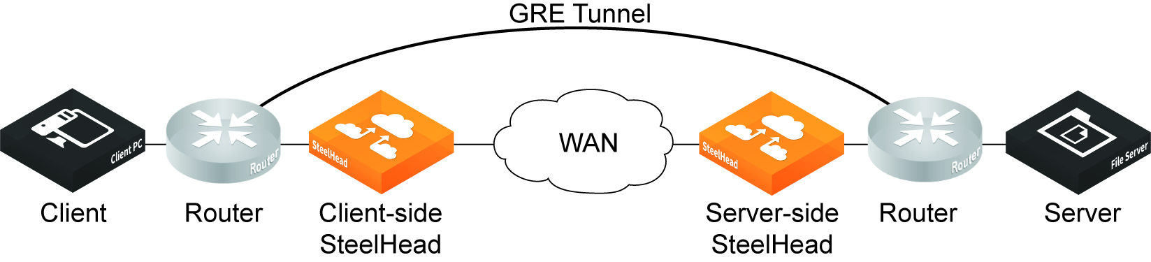
GRE tunnel optimization
Starting with RiOS 9.7, Generic Routing Encapsulation (GRE) between two SteelHead appliances can be inspected and optimized. Enable the GRE tunnel optimization features with the in-path peering-gre command.
Supported topologies for GRE tunnel optimization
GRE optimization supports hub-and-spoke and spoke-to-spoke topologies. A maximum of 100 tunnels is supported on a hub-and-spoke topology or a spoke-to-spoke topology.
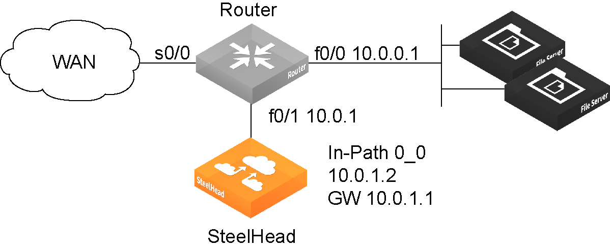
The GRE tunnel must be started and terminated between two routers. In addition, the default route for the client-side SteelHead and server-side SteelHeads should be directed to the WAN. Multiple SteelHead appliances can be used in a point-to-point GRE tunnel, as long as all of the SteelHeads are inside the tunnel.
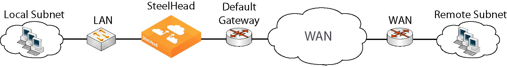
This figure shows a sample supported topology for GRE optimization.
Simple topology example for GRE optimization
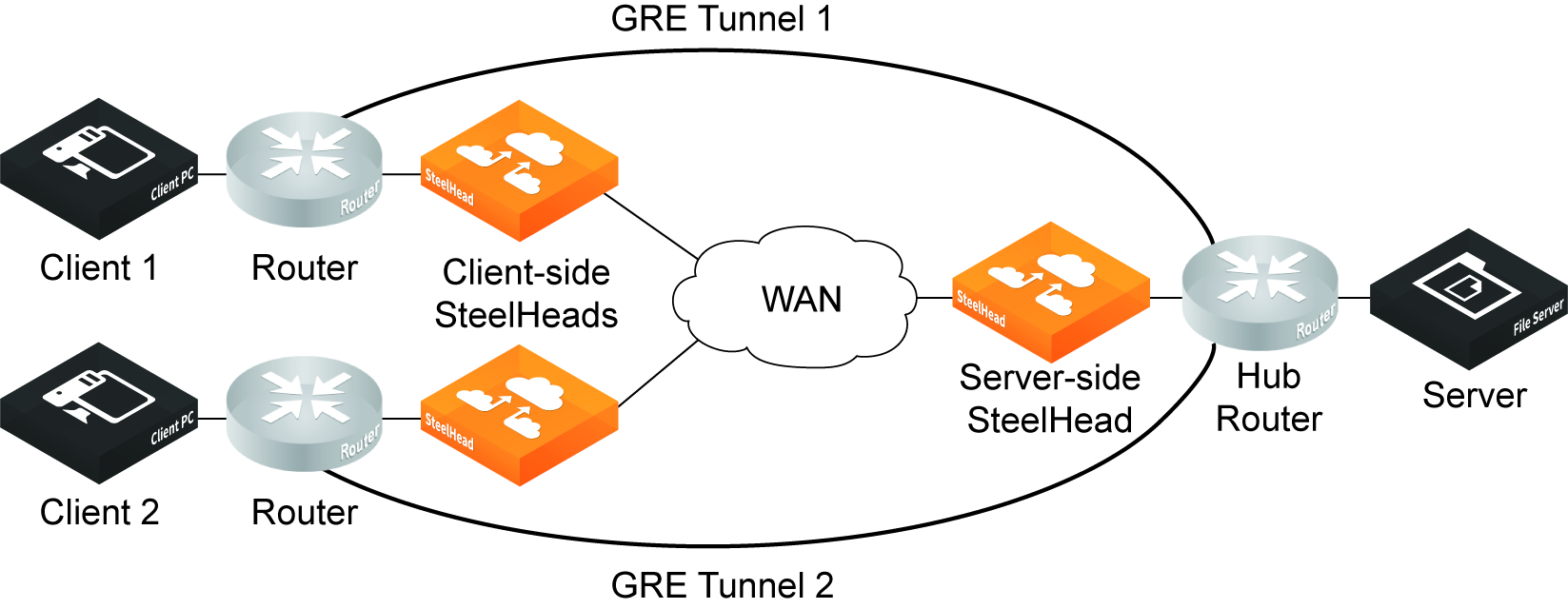
This figure shows a spoke-to-spoke topology with two GRE tunnels. Two client-side SteelHeads and a single server-side SteelHead terminate the optimized connections.
Simple spoke-to-spoke topology for GRE optimization
Supported appliances
The following SteelHead appliances support GRE tunnel optimization:
•CX3070, CX5070, CX7070, CX3080, CX5080, CX7080 SteelHead appliances
•SteelHead-v appliances on both KVM and ESXi platforms
Supported features
The following features are supported with GRE tunnel optimization:
•TCP optimization and pass-through
•FTP optimization
•HTTP/HTTPS optimization
•SMBv2 optimization
•NFS optimization
•Video over HTTP/HTTPS optimization
•MAPI optimization
•MX-TCP QoS support
•Simplified routing
•VLAN support
•Full transparency and correct addressing WAN visibility modes
Unsupported features
The following traffic is not optimized with GRE tunnel optimization:
•Out-of-band (OOB) traffic is not optimized. If OOB connections are received from a GRE tunnel, they will be relayed instead of optimized.
•Checksum, key, and sequence numbers are not optimized.
The following features are not supported:
•Asymmetric routing
•QoS classification (except MX-TCP)
•Single-ended interception
•Web Cache Communication Protocol (WCCP)
•Policy-based routing (PBR)
•UDP
•IPv6
•Port transparency WAN visibility mode (full transparency and correct addressing are supported)
•Path selection
•Double interception
•Asymmetric routing
•Interceptor support
Defining applications
You define applications in the Networking > App Definitions: Applications page.
Application definitions enable you to attach a business relevancy to all traffic that goes through your network. To simplify SteelHead configuration, the definition of an application is a separate task in RiOS 9.0 and later. A separate application definition allows you to configure multiple rules using the same application without having to repeat the application definition for each rule.
Application definitions also enable you to use application groups so that you can configure and reuse a single rule for multiple applications. Using application groups in a rule can reduce the number of rules significantly.
RiOS 9.0 and later separates application definition from the QoS rules. For more information about QoS rules, see
Configuring QoS.
We strongly recommend that you define applications and push application definitions from a SteelCentral Controller for SteelHead to the SteelHead appliances. For details, see the SteelCentral Controller for SteelHead Deployment Guide.
To view a list of predefined applications, see
Application Signatures for AFE.
Defining an application means that you group together a set of criteria to match certain traffic. After you define the criteria, you can use an application to configure QoS and path selection rules.
To define custom applications
1. Choose Networking > App Definitions: Applications to display the Applications page. The custom applications group is empty until you add application groups.
2. Select Custom Applications from the drop-down menu.
3. Click + Add.
4. Complete the name and description.
5. Specify the application traffic characteristics.
For easier configuration, you can use host labels instead of local and remote subnets and port labels instead of TCP/UDP port numbers.
In addition to criteria matching on the IP-header based characteristics or the VLAN ID, you can use the AFE to let RiOS automatically detect the application. See the description of the Application Layer Protocol control in the table for details.
6. Complete the configuration as described in this table.
Control | Description |
Traffic characteristics: |
Local Subnet or Host Label | Specify an IP address and mask for the traffic source, or you can specify all or 0.0.0.0/0 as the wildcard for all traffic. Use this format: xxx.xxx.xxx.xxx/xx. —or— Specify a host label. You predefine host labels on the Networking > App Definitions: Host Labels page. |
Port or Port Label | Optionally, specify all source ports, a single source port value or a port range of port1-port2, where port1 must be less than port2. The default setting is all ports. —or— Specify a port label. You predefine port labels on the Networking > App Definitions: Port Labels page. |
Remote Subnet or Host Label | Specify an IP address and mask pattern for the traffic destination, or you can specify all or 0.0.0.0/0 as the wildcard for all traffic. Use this format: xxx.xxx.xxx.xxx/xx. —or— Specify a host label. You predefine host labels on the Networking > App Definitions: Host Labels page. |
Transport Layer Protocol | Select a transport layer protocol from the drop-down list. The default setting is All. |
Application Layer Protocol | Specify an application layer protocol or an application signature. To specify an application signature, type the first letters of the application. For example, if you want to create specific criteria to identify Facebook traffic, type the first three letters and select a Facebook application from the drop-down menu. |
Port
or
Port Label (if port labels have been defined) | Optionally, specify all destination ports, a single source port value or a port range of port1-port2, where port1 must be less than port2. The default setting is all ports. —or— Specify a port label. You predefine port labels on the Networking > App Definitions: Port Labels page. |
VLAN Tag ID | Optionally, specify a VLAN tag as follows: •Specify a numeric VLAN tag identification number from 0 to 4094. •Specify all to specify the rule applies to all VLANs. •Specify none to specify the rule applies to untagged connections. RiOS supports VLAN v802.1Q. To configure VLAN tagging, configure transport rules to apply to all VLANs or to a specific VLAN. By default, rules apply to all VLAN values unless you specify a particular VLAN ID. Pass-through traffic maintains any preexisting VLAN tagging between the LAN and WAN interfaces. |
DSCP | Optionally, specify a DSCP value from 0 to 63, or all to use all DSCP values. |
Traffic Type | Select Optimized, Passthrough, or All from the drop-down list. The default setting is All. |
Application properties: |
Application Group | Select an application group for the application from the drop-down list (highest priority to lowest): Business Bulk - Captures business-level file transfer applications and protocols, such as CIFS, SCCM, antivirus updates, and over-the-network backup protocols. Business Critical - Captures business-level, low-latency transactional applications and protocols, such as SQL, SAP, Oracle and other database protocols, DHCP, LDAP, RADIUS, the Riverbed Control Channel (to identify and specify a DSCP value for out-of-band traffic), routing, and other network communication protocols. Business Productivity - Captures general business-level productivity applications and protocols, such as email, messaging, streaming and broadcast audio/video, collaboration, intranet HTTP traffic, and business cloud services O365, Google apps, SFDC, and others through a white list. Business Standard - Captures all intranetwork traffic going within local subnets as defined by the uplinks on the SteelHead. Use this class to define the default path for traffic not classified by other application groups. Business VDI - Captures real-time interactive business-level virtual desktop interface (VDI) protocols, such as PC over IP (PCoIP), Citrix CGP and ICA, RDP, VNC, and Telnet protocols. Business Video - Captures business-level video conferencing applications and protocols, such as Microsoft Lync and RTP video. Business Voice - Captures business-level voice over IP (VoIP) applications and protocols (signaling and bearer), such as Microsoft Lync, RTP, H.323 and SIP. Recreational - Captures all Internet-bound traffic that has not already been classified and processed by other application groups. Standard Bulk - Captures general file transfer protocols, such as FTP, torrents, NNTP/usenet, NFS, and online file hosting services Dropbox, Box.net, iCloud, MegaUpload, Rapidshare, and others. Custom Applications - Captures user-defined applications that have not been classified into another application group. |
Category | Select a category for the application from the drop-down list. |
Business Criticality | Select a service class for the application from the drop-down list: •Lowest Criticality - Specifies the lowest priority service class. •Low Criticality - Specifies a low-priority service class: for example, FTP, backup, replication, other high-throughput data transfers, and recreational applications such as audio file sharing. •Medium Criticality - Specifies a medium-priority service class. •High Criticality - Specifies a high-priority service class. •Highest Criticality - Specifies the highest priority service class. These are minimum service class guarantees; if better service is available, it’s provided. For example, if an application is specified as low priority and the higher-priority classes aren’t active, then the low-priority class receives the highest possible available priority for the current traffic conditions. This parameter controls the priority of the application relative to the other applications. Note: The service class describes only the delay sensitivity of a class, not how much bandwidth it’s allocated, nor how important the traffic is compared to other classes. Typically you configure low priority for high-throughput, non-packet delay sensitive applications like FTP, backup, and replication. |
7. Click Save to Disk to save your settings permanently.
Applying QoS policies
You apply Riverbed QoS policies in the Networking > Network Services: Quality of Service page. This section describes how SteelHeads use Riverbed QoS policies to allocate bandwidth and latency priorities.
For details about QoS, including integrating SteelHeads into an existing QoS implementation, see the SteelHead Deployment Guide. The SteelHead Deployment Guide also includes configuration examples and Riverbed QoS best practices.
QoS overview
QoS is a reservation system for network traffic. In its most basic form, QoS allows organizations to allocate scarce network resources across multiple traffic types of varying importance. QoS implementations allow organizations to accurately control their applications by the amount of bandwidth they have access to and by their sensitivity to delay.
QoS enhancements by version
This section lists and describes new QoS features and enhancements by RiOS version.
RiOS 9.5 introduced major changes to the Networking > Network Services: Quality of Service page:
•The Manage QoS Per Interface and QoS Remote Site panes are collapsed. Click the triangle next to the panes to expand them.
•A Local Site Uplink Bandwidth pane is added to let you add uplinks and quickly change the inbound and outbound bandwidth of the local site based on available bandwidth.
You can still access and edit these bandwidth values in the Networking > Topology: Sites & Networks page by editing the local site.
•The Default QoS Classes pane has a graphic representation of the default QoS classes for the default QoS profile, with an Edit button that lets you change it.
RiOS 9.1 provides these enhancements:
•Differentiated Service Code Point (DSCP) Marking to Prioritize Out-of-Band (OOB) Control Channel Traffic - An OOB connection is a TCP connection that SteelHeads establish with each other when they begin optimizing traffic to exchange capabilities and feature information such as licensing information, hostname, RiOS version, and so on. The SteelHeads also use control channel information to detect failures. You can now mark OOB connections with a DSCP or ToS IP value to prioritize or classify the Riverbed control channel traffic, preventing dropped packets in a lossy or congested network to guarantee control packets will get through and not be subject to unexpected tear down.
•Increase in Applications Recognized by the AFE - Application signatures classify QoS at an application level using the Application Flow Engine (AFE). The AFE provides an efficient and accurate way to identify applications for advanced classification and shaping of network traffic.
You can verify the application signatures available in your software version from within the Management Console. Type the first few letters of the application in the Application Protocol or Application field for QoS configuration. As you type the name of an application, a menu appears and lists available applications that match your typing.
RiOS 9.0 provides these enhancements:
•Easy QoS Configuration - Simplifies configuration of application properties and QoS classes. Now you can start with a basic QoS model and create per-site exceptions only as needed. Additionally, you no longer need to build individual rules to identify and classify traffic for QoS marking and shaping, because you can use application groups and application signatures for faster and easier configuration. For details on application groups, see
Defining applications.
•QoS Profiles - Create a fully customizable class-shaping hierarchy containing a set of rules and classes. View the class layout and details at a glance and reuse the profiles with multiple sites in both inbound and outbound QoS. Profiles in RiOS 9.0 and later replace service policies in previous versions.
•Inbound QoS and Outbound QoS Feature Parity - Removes inbound QoS restrictions to achieve full feature parity with outbound QoS.
RiOS 8.6 provides these enhancements:
•SSL Common Name Matching - Classify SSL pass-through traffic using a common name in a QoS rule.
•Substantial Increase in Applications Recognized by the AFE - Application signatures classify QoS at an application level using the AFE. The AFE provides an efficient and accurate way to identify applications for advanced classification and shaping of network traffic.
RiOS 8.5 provides these enhancements:
•SnapMirror Support - Use outbound QoS to prioritize SnapMirror replication jobs or shape optimized SnapMirror traffic that is sharing a WAN link with other enterprise protocols. QoS recognizes SnapMirror optimized flows and provisions five different service levels for each packet, based on priorities. You can also distinguish a job priority by filer and volume. You can create a QoS rule for the appropriate site and optionally specify a service class and DSCP marking per priority.
•Export QoS Configuration Statistics to a CascadeFlow Collector - CascadeFlow collectors can aggregate information about QoS configuration and other application statistics to send to a SteelCentral NetProfiler. The Enterprise NetProfiler summarizes and displays the QoS configuration statistics. For details, see
Configuring flow statistics.
•LAN Bypass - Virtual in-path network topologies in which the LAN-bound traffic traverses the WAN interface might require that you configure the SteelHead to bypass LAN-bound traffic so it’s not subject to the maximum root bandwidth limit. RiOS 7.0.3 introduced LAN bypass for QoS outbound shaping; RiOS 8.5 and later include inbound QoS shaping.
•Host Label Handling - Specify a range of hostnames and subnets within a single QoS rule.
•Global DSCP Marking - By default, the setup of optimized connections and the out-of-band control connections aren’t marked with a DSCP value. Existing traffic marked with a DSCP value is classified into the default class. If your existing network provides multiple classes of service based on DSCP values, and you are integrating a SteelHead into your environment, you can use the Global DSCP feature to prevent dropped packets and other undesired effects.
•QoS with IPv6 - RiOS 8.5 and later don’t support IPv6 traffic for QoS shaping or AFE-based classification. If you enable QoS shaping for a specific interface, all IPv6 packets for that interface are classified to the default class. You can mark IPv6 traffic with an IP ToS value. You can also configure the SteelHead to reflect an existing traffic class from the LAN-side to the WAN-side of the SteelHead.
QoS classes are based on traffic importance, bandwidth needs, and delay-sensitivity. You allocate network resources to each of the classes. Traffic flows according to the network resources allocated to its class.
You configure QoS on client-side and server-side SteelHeads to control the prioritization of different types of network traffic and to ensure that SteelHeads give certain network traffic (for example, Voice over IP (VoIP) higher priority over other network traffic.
Traffic classification
QoS allows you to specify priorities for particular classes of traffic and properly distribute excess bandwidth among classes. The QoS classification algorithm provides mechanisms for link sharing and priority services while decoupling delay and bandwidth allocation.
Many QoS implementations use some form of Packet Fair Queueing (PFQ), such as Weighted Fair Queueing or Class-Based Weighted Fair Queueing. As long as high-bandwidth traffic requires a high priority (or vice-versa), PFQ systems perform adequately. However, problems arise for PFQ systems when the traffic mix includes high-priority, low-bandwidth traffic, or high-bandwidth traffic that doesn’t require a high priority, particularly when both of these traffic types occur together. Features such as low-latency queueing (LLQ) attempt to address these concerns by introducing a separate system of strict priority queueing that is used for high-priority traffic. However, LLQ isn’t an effective way of handling bandwidth and latency trade-offs. LLQ is a separate queueing mechanism meant as a workaround for PFQ limitations.
The Riverbed QoS system isn’t based on PFQ, but rather on Hierarchical Fair Service Curve (HFSC). HFSC delivers low latency to traffic without wasting bandwidth and delivers high bandwidth to delay-insensitive traffic without disrupting delay-sensitive traffic. The Riverbed QoS system achieves the benefits of LLQ without the complexity and potential configuration errors of a separate queueing mechanism.
The SteelHead HFSC-based QoS enforcement system provides the flexibility needed to simultaneously support varying degrees of delay requirements and bandwidth usage. For example, you can enforce a mix of high-priority, low-bandwidth traffic patterns (for example, SSH, Telnet, Citrix, RDP, and CRM systems) with lower priority, high-bandwidth traffic (for example, FTP, backup, and replication). RiOS QoS allows you to protect delay-sensitive traffic such as VoIP, as well as other delay-sensitive traffic such as RDP and Citrix. You can do this without having to reserve large amounts of bandwidth for their traffic classes.
QoS classification occurs during connection setup for optimized traffic, before optimization and compression. QoS shaping and enforcement occurs after optimization and compression.
By design, QoS is applied to both pass-through and optimized traffic; however, you can choose to classify either pass-through or optimized traffic. QoS is implemented in the operating system; it’s not a part of the optimization service. When the optimization service is disabled, all the traffic is pass-through and is still shaped by QoS.
Flows can be incorrectly classified if there are asymmetric routes in the network when any of the QoS features are enabled.
QoS recommendations
We recommend the maximum classes, rules, and sites shown in this table for optimal performance and to avoid delays while changing the QoS configuration.
The QoS bandwidth limits are global across all WAN interfaces and the primary interface.
Traffic that passes through a SteelHead but isn’t destined to the WAN isn’t subject to the QoS bandwidth limit. Examples of traffic that isn’t subject to the bandwidth limits include routing updates, DHCP requests, and default gateways on the WAN-side of the SteelHead that redirect traffic back to other LAN-side subnets.
SteelHead CX model | Recommended maximum configurable root bandwidth (Mbps) | Recommended maximum classes | Recommended maximum rules | Recommended maximum sites |
CX255P | 6 | 300 | 300 | 50 |
CX255U | 10 | 300 | 300 | 50 |
CX255L | 12 | 300 | 300 | 50 |
CX255M | 12 | 300 | 300 | 50 |
CX255H | 12 | 300 | 300 | 50 |
CX570L | 12 | 500 | 500 | 50 |
CX570M | 20 | 500 | 500 | 50 |
CX570H | 20 | 500 | 500 | 50 |
CX770L | 45 | 1000 | 1000 | 100 |
CX770M | 45 | 1000 | 1000 | 100 |
CX770H | 45 | 1000 | 1000 | 100 |
For the following appliance models, the network services flows and WAN capacity replace the maximum configurable QoS root bandwidth in previous RiOS versions. Network services include these features: path selection, secure transport, SteelFlow, and the Application Flow Engine (AFE).
The recommended QoS values for the CX580, CX780, and CX3080 are not finalized as of the 9.9.1 release date. When finalized, the recommended QoS values for these appliances will be published in the SteelHead Product Family Specification Sheet.
For the GX10000, the total recommended number of classes and rules cannot exceed 4,000.
CX model | Network services flows | Network services WAN capacity (Mbps) | Recommended maximum classes | Recommended maximum rules | Recommended maximum sites |
CX3070L | 48,000 | 250 | 1,000 | 1,000 | 200 |
CX3070M | 48,000 | 500 | 1,000 | 1,000 | 200 |
CX3070H | 48,000 | 500 | 1,000 | 1,000 | 200 |
CX5070M | 96,000 | Unrestricted | 2,000 | 2,000 | 500 |
CX5070H | 96,000 | Unrestricted | 2,000 | 2,000 | 500 |
CX7070L | 192,000 | Unrestricted | 2,000 | 2,000 | 500 |
CX7070M | 256,000 | Unrestricted | 2,000 | 2,000 | 500 |
CX7070H | 512,000 | Unrestricted | 2,000 | 2,000 | 500 |
CX5080-B010 | 160,000 | Unrestricted | 3,000 | 3,000 | 500 |
CX7080-B010 | 160,000 | Unrestricted | 3,000 | 3,000 | 500 |
CX7080-B020 | 320,000 | Unrestricted | 3,000 | 3,000 | 500 |
CX7080-B030 | 800,000 | Unrestricted | 3,000 | 3,000 | 500 |
GX10000 | 768,000 | Unrestricted | 2,000 | 2,000 | 500 |
Bypassing LAN traffic
We recommend a maximum limit on the configurable root bandwidth for the WAN interface. The hardware platform determines the recommended limit. For details, see
QoS recommendations.
Certain virtual in-path network topologies where the LAN-bound traffic traverses the WAN interface might require that the SteelHead bypass LAN-bound traffic so that it’s not included in the rate limit determined by the recommended maximum root bandwidth. Some deployment examples are WCCP or a WAN-side default gateway.
In-path configuration where default LAN gateway is accessible over the SteelHead WAN interface and
WCCP configuration where default LAN gateway is accessible over the SteelHead WAN interface illustrate topologies where the default LAN gateway or router is accessible over the WAN interface of the SteelHead. If there are two clients in the local subnet, traffic between the two clients is routable after reaching the LAN gateway. As a result, this traffic traverses the WAN interface of the SteelHead.
In-path configuration where default LAN gateway is accessible over the SteelHead WAN interface
WCCP configuration where default LAN gateway is accessible over the SteelHead WAN interface
In a QoS configuration for these topologies, suppose you have several QoS classes created and the root class is configured with the WAN interface rate. The remainder of the classes use a percentage of the root class. In this scenario, the LAN traffic is rate limited because RiOS classifies it into one of the classes under the root class.
You can use the LAN bypass feature to exempt certain subnets from QoS enforcement, bypassing the rate limit. The LAN bypass feature is enabled by default and comes into effect when subnet side rules are configured.
To filter the LAN traffic from the WAN traffic
1. If QoS isn’t running, choose Networking > Network Services: Quality of Service and enable inbound or outbound QoS Shaping.
2. Choose Networking > Network Services: Subnet Side Rules.
3. Click Add a Subnet Side Rule.
4. Select Start, End, or a rule number from the drop-down list.
5. Specify the client-side SteelHead subnet using the format <ip-address>/<subnet-mask>.
6. Select Subnet address is on the LAN side of the appliance.
7. Click Add.
To verify the traffic classification, choose Reports > Networking: Inbound QoS or Outbound QoS.
The SteelHead processes the subnet side LAN rules before the QoS outbound rules.
In virtual-in-path deployment, using subnet side rules is the same for QoS and NetFlow. In an in-path deployment, NetFlow discards the subnet side rules.
QoS classification for the FTP data channel
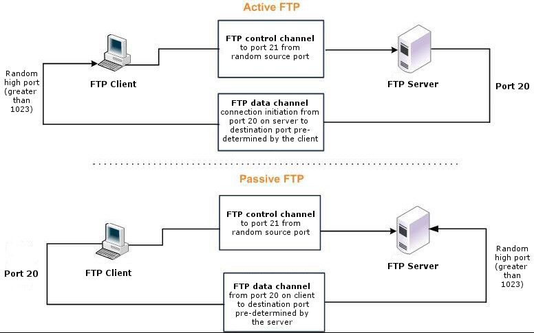
When configuring QoS classification for FTP, the QoS rules differ depending on whether the FTP data channel is using active or passive FTP. Active versus passive FTP determines whether the FTP client or the FTP server select the port connection for use with the data channel, which has implications for QoS classification.
The AFE doesn’t support passive FTP. Because passive FTP uses random high TCP port numbers to set up its data channel from the FTP server to the FTP client, the FTP data traffic can’t be classified on the TCP port numbers. To classify passive FTP traffic, you can add an application rule where the application is FTP and matches the IP address of the FTP server.
Active FTP classification
With active FTP, the FTP client logs in and enters the PORT command, informing the server which port it must use to connect to the client for the FTP data channel. Next, the FTP server initiates the connection toward the client. From a TCP perspective, the server and the client swap roles. The FTP server becomes the client because it sends the SYN packet, and the FTP client becomes the server because it receives the SYN packet.
Although not defined in the RFC, most FTP servers use source port 20 for the active FTP data channel.
For active FTP, configure a QoS rule on the server-side SteelHead to match source port 20. On the client-side SteelHead, configure a QoS rule to match destination port 20.
You can also use AFE to classify active FTP traffic.
Passive FTP classification
With passive FTP, the FTP client initiates both connections to the server. First, it requests passive mode by entering the PASV command after logging in. Next, it requests a port number for use with the data channel from the FTP server. The server agrees to this mode, selects a random port number, and returns it to the client. Once the client has this information, it initiates a new TCP connection for the data channel to the server-assigned port. Unlike active FTP, there’s no role swapping and the FTP client initiates the SYN packet for the data channel.
The FTP client receives a random port number from the FTP server. Because the FTP server can’t return a consistent port number to use with the FTP data channel, RiOS doesn’t support QoS Classification for passive FTP in versions earlier than RiOS 4.1.8, 5.0.6, or 5.5.1. Later RiOS releases support passive FTP and the QoS Classification configuration for passive FTP is the same as active FTP.
When configuring QoS Classification for passive FTP, port 20 on both the server-side and client-side SteelHeads indicates the port number used by the data channel for passive FTP, as opposed to the literal meaning of source or destination port 20.
The SteelHead must intercept the FTP control channel (port 21), regardless of whether the FTP data channel is using active or passive FTP.
Active and passive FTP
QoS classification for Citrix traffic
RiOS 9.x doesn’t support packet-order queueing or latency priorities with Citrix traffic. We recommend using either the Autonegotiation of Multi-Stream ICA feature or the Multi-Port feature to classify Citrix traffic types for QoS. For details, see
Configuring Citrix optimization.
RiOS 8.6.x and earlier provide a way to classify Citrix traffic using QoS to differentiate between different traffic types within a Citrix session. QoS classification for Citrix traffic is beneficial in mixed-use environments where Citrix users perform printing and use drive-mapping features. Using QoS to classify Citrix traffic in a mixed-use environment provides optimal network performance for end users.
Citrix QoS classification provides support for Presentation Server 4.5, XenApp 5.0 and 6.0, and 10.x, 11.x, and 12.x clients.
The essential RiOS capabilities that ensure optimal delivery of Citrix traffic over the network are:
•Latency priority - The Citrix traffic application priority affects traffic latency, which allows you to assign interactive traffic a higher priority than print or drive-mapping traffic. A typical application priority for interactive Citrix sessions, such as screen updates, is real-time or interactive. Keep in mind that priority is relative to other classes in your QoS configuration.
•Bandwidth allocation (also known as traffic shaping) - When configuring QoS for Citrix traffic, it’s important to allocate the correct amount of bandwidth for each QoS traffic class. The amount you specify reserves a predetermined amount of bandwidth for each traffic class. Bandwidth allocation is important for ensuring that a given class of traffic can’t consume more bandwidth than it is allowed. It’s also important to ensure that a given class of traffic has a minimum amount of bandwidth available for delivery of data through the network.
The default ports for the Citrix service are 1494 (native ICA traffic) and 2598 (session reliability). To use session reliability, you must enable Citrix optimization on the SteelHead in order to classify the traffic correctly. You can enable and modify Citrix optimization settings in the Optimization > Protocols: Citrix page. For details, see
Configuring Citrix optimization.
You can use session reliability with optimized traffic only. Session reliability with RiOS QoS doesn’t support pass-through traffic. For details about disabling session reliability, go to
http://support.citrix.com/proddocs/index.jsp?topic=/xenapp5fp-w2k8/ps-sessions-sess-rel.html.If you upgrade from a previous RiOS version with an existing Citrix QoS configuration, the upgrade automatically combines the five preexisting Citrix rules into one.
For QoS configuration examples, see the SteelHead Deployment Guide.
Configuring QoS
This section describes how to configure QoS. It contains these topics:
Overview
QoS configuration identifies business applications and classifies traffic according to priorities. The SteelHead uses this information to control the amount of WAN resources that each application can use. QoS ensures that your important applications are prioritized and removes the guesswork from protecting performance of key applications. In addition, QoS can prevent recreational applications from interfering with business applications.
We strongly recommend that you configure QoS on and push QoS policies from a SteelCentral Controller for SteelHead to the SteelHead appliances, particularly with large scale deployments. For details, see the SteelCentral Controller for SteelHead Deployment Guide.
Every SteelHead has predefined classes that categorize network traffic. For more information, see
Viewing and editing the default QoS classes. You can keep the default classes, or modify them by adding subclasses and rules. See
Adding QoS profiles and
Adding and editing QoS rules for more information.
A useful way to configure QoS is to add a subclass or rule and use group applications and application signatures that come predefined with RiOS. To find applications available in your version of the software, see
Application Signatures for AFE. For the list of application groups, and to create a custom application, see
Defining applications.
Before configuring QoS, we recommend that you define any applications that are not already defined. See
Defining applications for more information.
And all in-path interfaces are enabled for inbound and outbound QoS with the same link rate.
If you are migrating from RiOS 8.6.x and earlier to RiOS 9.x, see the SteelHead Installation and Configuration Guide for the migration process.
To enable QoS
1. Choose Networking > Network Services: Quality of Service to display the Quality of Service page.
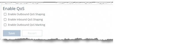
Quality of Service page—Enable QoS pane
2. Under Enable QoS, complete the following configuration.
•Enable Outbound QoS Shaping - Enables QoS classification to control the prioritization of different types of network traffic and to ensure that the SteelHead gives certain network traffic (for example, Voice over IP) higher priority than other network traffic. Traffic is not classified until at least one WAN interface is enabled. The system enables inbound and outbound QoS on all in-path interfaces by default.
To disable outbound QoS, clear this check box.
•Enable Inbound QoS Shaping - Enables QoS classification to allocate bandwidth and prioritize traffic flowing into the LAN network behind the SteelHead. Inbound QoS provides the benefits of QoS for environments that can’t meet their QoS requirements with outbound QoS.
To disable inbound QoS, clear this check box.
•Enable Outbound QoS Marking - Identifies outbound traffic using marking values. You can mark traffic using header parameters such as VLAN, DSCP, and protocols. You can also use Layer-7 protocol information through Application Flow Engine (AFE) inspection to apply DSCP marking values to traffic flows.
The DSCP or IP ToS marking only has local significance. You can set the DSCP or IP ToS values on the server-side SteelHead to values different to those set on the client-side SteelHead.
3. Click Save to apply your settings.
4. Click Save to Disk to save your settings permanently.
To manage QoS settings per interface
1. Choose Networking > Network Services: Quality of Service to display the Quality of Service page.
2. Click the arrow to the left of the Manage QoS settings per interface pane to expand it.
Quality of Service page—Manage QoS Per Interface pane
3. Click the right arrow next to the WAN interface name and then select Outbound or Inbound QoS.
By default, the system enables inbound and outbound QoS on all in-path interfaces except the primary interface. You can only enable outbound QoS on the primary interface.
Inbound QoS supports in-path interfaces only; it doesn’t support primary or auxiliary interfaces.
4. Click Save to apply your settings.
5. Click Save to Disk to save your settings permanently.
To set the uplink bandwidth for local uplinks
1. Choose Networking > Network Services: Quality of Service to display the Quality of Service page.
2. In the Local Site Uplink Bandwidth pane, click the arrow next to an uplink name to expand it.
Local Site Uplink Bandwidth pane
3. Specify the inbound (Bandwidth Down) and outbound (Bandwidth Up) bandwidth for the uplinks on the local site, in kilobits per second.
RiOS uses the bandwidth to precompute the end-to-end bandwidth for QoS. The SteelHead automatically sets the bandwidth for the default site to this value.
The rate is the bottleneck WAN bandwidth, not the interface speed out of the WAN interface into the router or switch. As an example, if your SteelHead connects to a router with a 100 Mbps link, don’t specify this value—specify the actual WAN bandwidth (for example, T1, T3).
Different WAN interfaces can have different WAN bandwidths; you must enter the bandwidth link rate correctly for QoS to function properly.
You can also access and edit these bandwidth values, in addition to site-specific tasks such as adding an uplink, in the Networking > Topology: Sites & Networks page. For more information, see
Defining a site.
4. Click Save to apply your settings.
5. Click Save to Disk to save your settings permanently.
Viewing and editing the default QoS classes
Starting with RiOS 9.5, there is no default profile in the QoS Profiles pane. Instead, SteelHeads display a set of default QoS classes in the Default QoS Classes pane. These classes take the place of the default QoS profile. To view the classes, choose Networking > Network Services: Quality of Service.
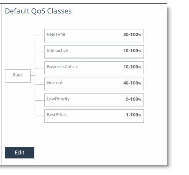
Default QoS Classes pane
The default classes represent the following types of traffic:
RealTime - Specifies real-time traffic class. Give this value to the highest-priority traffic: for example, VoIP or video conferencing.
Interactive - Specifies an interactive traffic class: for example, Citrix, RDP, telnet, and SSH.
BusinessCritical - Specifies the high-priority traffic class: for example, Thick Client Applications, ERPs, and CRMs.
Normal - Specifies a normal- priority traffic class: for example, internet browsing, file sharing, and email.
LowPriority - Specifies a low-priority traffic class: for example, FTP, backup, replication, other high-throughput data transfers, and recreational applications such as audio file sharing.
BestEffort - Specifies the lowest priority.
The QoS class indicates how delay-sensitive a traffic class is to the QoS scheduler. These are minimum service class guarantees; if better service is available, it’s provided. For example, if a class is specified as low priority and the higher-priority classes aren’t active, then the low-priority class receives the highest possible available priority for the current traffic conditions. This parameter controls the priority of the class relative to the other classes.
The service class describes only the delay sensitivity of a class, not how important the traffic is compared to other classes. Typically you configure low priority for high-throughput, non-packet delay sensitive applications like FTP, backup, and replication.
Classes are organized in a hierarchical tree structure. You can use the default classes in rules as part of a profile by choosing Any (Default Rule) in the QoS Rules pane, which inherits the default classes.
To edit QoS classes
1. Choose Networking > Network Services: Quality of Service to display the Quality of Service page.
2. Under Default QoS Classes, click Edit.
3. Change the class values as shown in this table.
Control | Description |
Class Name | Specify a name for the QoS class. For information about the default classes, see Viewing and editing the default QoS classes. |
Minimum Bandwidth % | Specify the minimum amount of bandwidth (as a percentage) to guarantee to a traffic class when there’s bandwidth contention. All of the classes combined can’t exceed 100 percent. During contention for bandwidth, the class is guaranteed the amount of bandwidth specified. The class receives more bandwidth if there’s unused bandwidth remaining. Excess bandwidth is allocated based on the relative ratios of minimum bandwidth. The total minimum guaranteed bandwidth of all QoS classes must be less than or equal to 100 percent of the parent class. A default class is automatically created with minimum bandwidth of 10 percent. Traffic that doesn’t match any of the rules is put into the default class. We recommend that you change the minimum bandwidth of the default class to the appropriate value. You can adjust the value as low as 0 percent. |
Maximum Bandwidth % | Specify the maximum allowed bandwidth (as a percentage) a class receives as a percentage of the parent class minimum bandwidth. The limit’s applied even if there’s excess bandwidth available. |
Outbound Queue Type | Optionally, select one of these queue methods for the leaf class from the drop-down list (the queue doesn’t apply to the inner class): •SFQ - Shared Fair Queueing (SFQ) is the default queue for all classes. Determines SteelHead behavior when the number of packets in a QoS class outbound queue exceeds the configured queue length. When SFQ is used, packets are dropped from within the queue in a round-robin fashion, among the present traffic flows. SFQ ensures that each flow within the QoS class receives a fair share of output bandwidth relative to each other, preventing bursty flows from starving other flows within the QoS class. •FIFO - Transmits all flows in the order that they’re received (first in, first out). Bursty sources can cause long delays in delivering time-sensitive application traffic and potentially to network control and signaling messages. •MX-TCP - Has very different use cases than the other queue parameters. MX-TCP also has secondary effects that you must understand before configuring: –When optimized traffic is mapped into a QoS class with the MX-TCP queuing parameter, the TCP congestion-control mechanism for that traffic is altered on the SteelHead. The normal TCP behavior of reducing the outbound sending rate when detecting congestion or packet loss is disabled, and the outbound rate is made to match the guaranteed bandwidth configured on the QoS class. –You can use MX-TCP to achieve high-throughput rates even when the physical medium carrying the traffic has high-loss rates. For example,
MX-TCP is commonly used for ensuring high throughput on satellite connections where a lower-layer-loss recovery technique is not in use. RiOS 8.5 and later introduce rate pacing for satellite deployments, which combines MX-TCP with a congestion-control method. –Another use of MX-TCP is to achieve high throughput over high-bandwidth, high-latency links, especially when intermediate routers don’t have properly tuned interface buffers. Improperly tuned router buffers cause TCP to perceive congestion in the network, resulting in unnecessarily dropped packets, even when the network can support high-throughput rates. You must ensure the following when you enable MX-TCP: – The QoS rule for MX-TCP must be at the top of QoS rules list. – Only use MX-TCP for optimized traffic. MX-TCP doesn’t work for unoptimized traffic. –Do not classify a traffic flow as MX-TCP and then subsequently classify it in a different queue. –There is a maximum bandwidth setting for MX-TCP that allows traffic in the MX class to burst to the maximum level if the bandwidth is available. |
Outbound DSCP | Selects the default DSCP mark for the class. QoS rules can then specify Inherit from Class for outbound DSCP to use the class default. Select Preserve or a DSCP value from the drop-down list. This value is required when you enable QoS marking. The default setting is Preserve, which specifies that the DSCP level or IP ToS value found on pass-through and optimized traffic is unchanged when it passes through the SteelHead. The DSCP marking values fall into these classes: •Expedited forwarding (EF) class - In this class, packets are forwarded regardless of link share of other traffic. The class is suitable for preferential services requiring low delay, low packet loss, low jitter, and high bandwidth. •Assured forwarding (AF) class - This class is divided into four subclasses, each containing three drop priorities for more granular classification. The QoS level of the AF class is lower than that of the EF class. 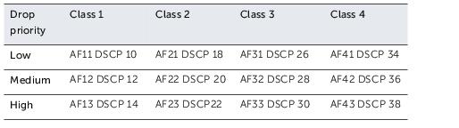 •Class selector (CS) class - This class is derived from the IP ToS field. |
Priority | Select a latency priority from 1 through 6, where 1 is the highest and 6 is the lowest. |
4. Optionally, add a new class and enter the values for the new class.
•To add an additional class as a peer with the existing classes, click add class at the bottom of the tree.
•To add an additional class as a subclass of an existing class, click add class to the right of the existing class.
Use a hierarchical tree structure to:
–divide traffic based on flow source or destination and apply different shaping rules and priorities to each leaf-class.
–effectively manage and support remote sites with different bandwidth characteristics.
The SteelHead Management Console supports the configurations of three hierarchy levels. If you need more levels of hierarchy, you can configure them using the CLI. See the documentation for the qos profile class command in the Riverbed Command-Line Interface Reference Manual.
•To remove the class, click the x at the corner of the window. To remove a parent class, delete all rules for the corresponding child classes first. When a parent class has rules or children, the x for the parent class is unavailable.
5. Click Save to save the changes to the default class.
6. Click Save to Disk to save your settings permanently.
Adding QoS profiles
You can create additional profiles to set QoS classes and rules for multiple sites. For details about sites, see
Defining a site. For details about QoS, see the
SteelHead Deployment Guide and the
QoS on SteelHeads Feature Module.
A QoS profile contains a set of QoS classes and rules.
QoS profiles in RiOS 9.0 and later replace QoS service policies in previous versions.
To add a profile
1. Choose Networking > Network Services: Quality of Service to display the Quality of Service page.
2. Under QoS Profiles, click + Add a QoS Profile.
3. Specify a profile name.
4. In the Copy From: field, select a template or an existing profile on which to base the new profile. The system copies the existing configuration into the new profile. You can then fine-tune the parameters to create a new profile.
5. Click Save.
To edit a profile
1. Choose Networking > Network Services: Quality of Service to display the Quality of Service page.
Quality of Service page—QoS Profiles pane
2. Under QoS Profiles, click Edit to the right of the profile name.
Adding and editing QoS rules
In RiOS 9.0 and later, QoS rules assign traffic to a particular QoS class. Prior to RiOS 9.0, QoS rules defined an application; however, applications are now defined separately, and you can add application groups, application signatures, or custom applications as part of a rule. To learn how to find applications supported in the software, see
Application Signatures for AFE. For the list of application groups, and to create a custom application, see
Defining applications.
You can create multiple QoS rules for a profile. When multiple QoS rules are created for a profile, the rules are followed in the order in which they’re shown in the QoS Profile page and only the first matching rule is applied to the profile.
SteelHeads support up to 2000 rules and up to 500 sites. When a port label is used to add a QoS rule, the range of ports can’t be more than 2000 ports.
If a QoS rule is based on an application group, it counts as a single rule. Using application groups can significantly reduce the number of rules in a profile.
In RiOS 9.0 and later, QoS rules assign traffic to a particular QoS class. Prior to RiOS 9.0 QoS rules defined an application; now you use application properties. For more information, see
Defining applications.
Including the QoS rule in the profile prevents the repetitive configuration of QoS rules, because you can assign a QoS profile to multiple sites.
Make sure that you place the more granular QoS rules at the top of the QoS rules list. Rules from this list are applied from top to bottom. As soon as a rule is matched, the list is exited.
For more information about QoS profiles, see
Adding QoS profiles.
To add a QoS rule
1. Choose Networking > Network Services: Quality of Service.
2. Select Add a Rule in the Default QoS Rules pane.
Adding a new QoS rule
3. Start to type the application or application group name in the text box, then select it from the drop down menu of the available application and application groups.
Application or Application Group field prepopulation
4. Complete the other fields as described in this table.
Control | Description |
Application or Application Group | Specify the application or application group. We recommend using application groups for the easiest profile configuration and maintenance. |
QoS Class | Select a service class for the application from the drop-down list, or select Inherit from Default Rule. The classes are described in Viewing and editing the default QoS classes. Choose Inherit from Default Rule to use the class that is currently set for the default rule. The default setting is LowPriority. |
Outbound DSCP | Select Inherit from Class, Preserve, or a DSCP value from the drop-down list. This value is required when you enable QoS marking. The default setting is Inherit from Class. Preserve specifies that the DSCP level or IP ToS value found on pass-through and optimized traffic is unchanged when it passes through the SteelHead. When you specify a DSCP marking value in a rule, it either takes precedence over or inherits the value in a class. |
5. Click Save.
The newly created QoS rule displays in the QoS rules table of the QoS profile.
To configure or edit a QoS rule in a profile
1. Choose Networking > Network Services: Quality of Service.
2. In the Default QoS Rules pane, click the arrow next to the rule.
Editing a QoS rule for the default profile
To edit a rule for a profile that was added, scroll down to the QoS Profiles area, click Edit to the right of the QoS profile name, and then click the arrow next to the rule.
Editing a QoS rule for an added profile
3. Select Add a Rule at the bottom of the page.
4. Specify the first three or four letters of the application or application group you want to create a rule for and select it from the drop down menu of the available application and application groups.
Configuring a QoS rule in a profile
5. Edit the application or application group name, the QoS class, or the DSCP value in the rule.
6. Click Save.
Verifying and Saving a QoS Configuration
After you apply your settings, you can verify whether the traffic is categorized in the correct class by choosing Reports > Networking: Outbound QoS and viewing the report. For example, if you have configured VoIP traffic as real-time, check the real-time class and verify that existing classes aren’t receiving VoIP traffic.
You can verify whether the configuration is honoring the bandwidth allocations by reviewing the Outbound QoS and Inbound QoS reports.
When you have verified appropriate changes, you can write the active configuration that is stored in memory to the active configuration file (or you can save it as any filename you choose). For details about saving configurations, see
Managing configuration files.
Related topics
Enabling MX-TCP queue policies
When you define a QoS class, you can enable a maximum speed TCP (MX-TCP) queue policy, which prioritizes TCP/IP traffic to provide more throughput for high loss links or links that have large bandwidth and high latency LFNs. Some use case examples are:
•Data-Intensive Applications - Many large, data-intensive applications running across the WAN can negatively impact performance due to latency, packet loss, and jitter. MX-TCP enables you to maximize your TCP throughput for data intensive applications.
•High Loss Links - TCP doesn’t work well on misconfigured links (for example, an under-sized bottleneck queue) or links with even a small amount of loss, which leads to link under-utilization. If you have dedicated point-to-point links and want those links to function at predefined rates, configure the SteelHead to prioritize TCP traffic.
•Privately Owned Links - If your network includes privately owned links dedicated to rate-based TCP, configure the SteelHead to prioritize TCP traffic.
After enabling the MX-TCP queue to forward TCP traffic regardless of congestion or packet loss, you can assign QoS rules that incorporate this policy only to links where TCP is of exclusive importance.
These exceptions to QoS classes apply to MX-TCP queues:
•In RiOS 7.x and later, the Link Share Weight parameter doesn’t apply to MX-TCP queues. When you select the MX-TCP queue, the Link Share Weight parameter doesn’t appear. In RiOS 8.x and later, there’s a maximum bandwidth setting for MX-TCP that allows traffic to burst to the maximum level if the bandwidth is available.
•MX-TCP queues apply only to optimized traffic (that is, no pass-through traffic).
•MX-TCP queues can’t be configured to contain more bandwidth than the license limit.
When enabling MX-TCP, ensure that the QoS rule is at the top of QoS rules list.
Basic steps for MX-TCP
This table describes the basic steps to configure MX-TCP. Enabling this feature is optional.
Task | Reference |
1. Select each WAN interface and define the bandwidth link rate for each interface. | |
2. Add an MX-TCP class for the traffic flow. Make sure you specify MX-TCP as your queue. | |
3. Define QoS rules to point to the MX-TCP class. | |
4. Select the Enable Inbound or Outbound QoS Shaping check box and click Save. Your changes take effect immediately. | |
5. Optionally, to test a single connection, change the WAN socket buffer size (to at least the BDP). You must set this parameter on both the client-side and the server-side SteelHead. | |
6. Check and locate the inner connection. | |
7. Check the throughput. | |
Modifying QoS profiles
You can modify the profile name, QoS class properties, and QoS rule properties in the Networking > Network Services: QoS Profiles page. You can rename a profile name, class, or rule seamlessly without the need to manually update the associated resources. For example, if you rename a profile associated with a site, the system updates the profile name and the profile name within the site definition automatically.
For details on creating a profile, see
Adding QoS profiles.
To modify a QoS profile name, class, or rule
1. Choose Networking > Network Services: Quality of Service to display the Quality of Service page.
2. Click Edit next to the profile name in the QoS Profiles pane.
3. Perform any of these tasks (in any order):
–Rename the profile.
–Click Edit next to the class name and change its properties.
–Select a rule and change its properties.
4. Click Save to Disk to save your settings permanently.
Classifying and prioritizing OOB traffic using DSCP marking
When two SteelHeads see each other for the first time, either through autodiscovery or a fixed-target rule, they set up an out-of-band (OOB) splice. This is a control TCP session between the two SteelHeads that the system uses to test the connectivity between the two appliances.
After the setup of the OOB splice, the two SteelHeads exchange information about each other such as the hostname, licensing information, RiOS versions, capabilities, and so on. This information is included in the Riverbed control channel traffic.
By default, the control channel traffic isn’t marked with a DSCP value. By marking the control channel traffic with a DSCP or ToS IP value, you can prevent dropped packets and other undesired effects on a lossy or congested network link.
In RiOS 9.0 and earlier, the qos dscp-marking enable command enables global DSCP marking, which tags inner channel setup packets and OOB packets with a DSCP value. RiOS 9.1 and later let you use the management console to separate the inner channel setup packets from the OOB packets and mark the OOB control channel traffic with a unique DSCP value.
Before marking OOB traffic with a DSCP value, ensure that the global DSCP setting isn’t in use. Global DSCP marking includes both inner channel setup packets and OOB control channel traffic. This procedure separates the OOB traffic from the inner channel setup traffic. For details on disabling global DSCP marking, see the [no] qos dscp-marking enable command in the Riverbed Command-Line Interface Reference Manual.
To classify OOB traffic with a DSCP marking
1. Choose Networking > Network Services: Quality of Service to display the Quality of Service page.
2. Under QoS Profiles, click Edit next to the profile name to display the QoS Profile Details page.
3. Under QoS Rules, select Add a Rule.
4. In the Application or Application Group text box, select Riverbed Control Traffic (Client) if the SteelHead being configured is a client-side SteelHead. Select Riverbed Control Traffic (Server) if the SteelHead being configured is a server-side SteelHead.
OOB packets are marked on the server-side SteelHead based on the value configured on the client-side SteelHead if a rule isn’t explicitly configured on the server-side SteelHead.
5. Under Outbound DSCP, select a DSCP marking value or a ToS IP value from the drop-down list.
6. Click Save to save your settings.
7. Click Save to Disk to save your settings permanently.
The new QoS rule appears in the QoS Rules table.
Inbound QoS
You configure inbound QoS in the Networking > Network Services: Quality of Service page. RiOS 9.0 and later provide feature parity between outbound and inbound QoS.
Inbound QoS allocates bandwidth and prioritizes traffic flowing into the LAN network behind the SteelHead. Inbound QoS provides the benefits of QoS for environments that can’t meet their QoS requirements with outbound QoS.
Some examples of environments that can benefit from inbound QoS are:
•A deployment that doesn’t have a SteelHead located at the traffic source (for example, the traffic comes from the internet or from servers at a site without a SteelHead).
Guarantee bandwidth for incoming traffic
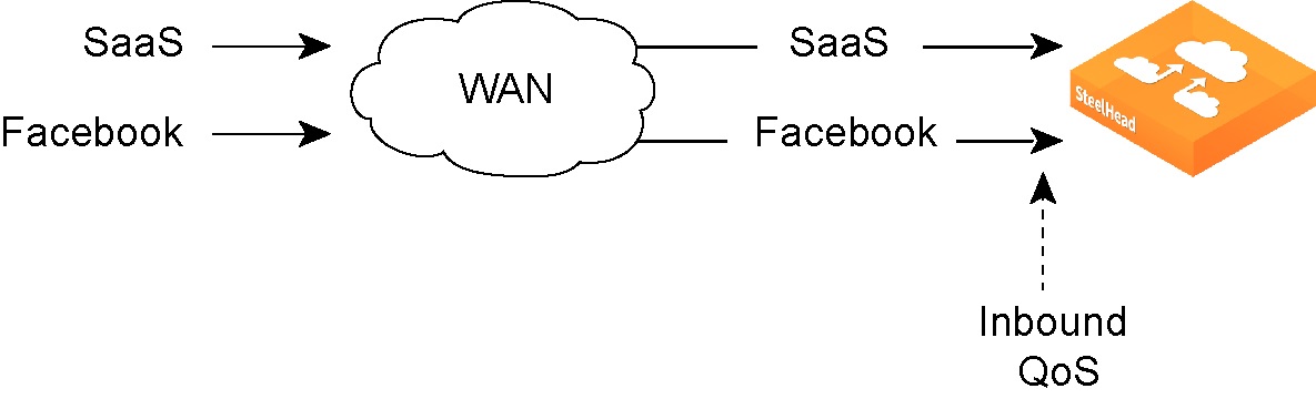
•A deployment that has multiple SteelHeads located at the traffic source (for example, behind an Interceptor cluster). The SteelHeads don’t share bandwidth information with each other. As a result, they can overwhelm the branch office site at the remote location.
Data center with multiple SteelHeads in a cluster
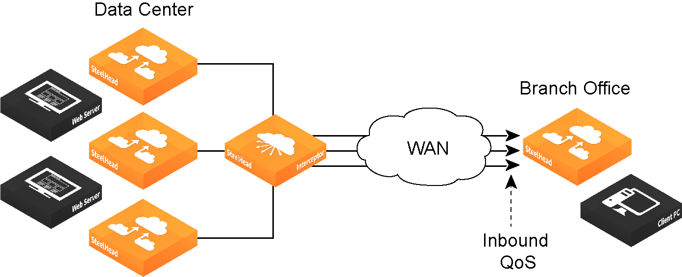
•A branch office receiving data from multiple data centers (either with or without SteelHeads). Because the two data centers don’t coordinate the amount of bandwidth sent to the branch office, they can overwhelm the link at the branch office, causing degraded performance.
Branch office that receives data from multiple data centers
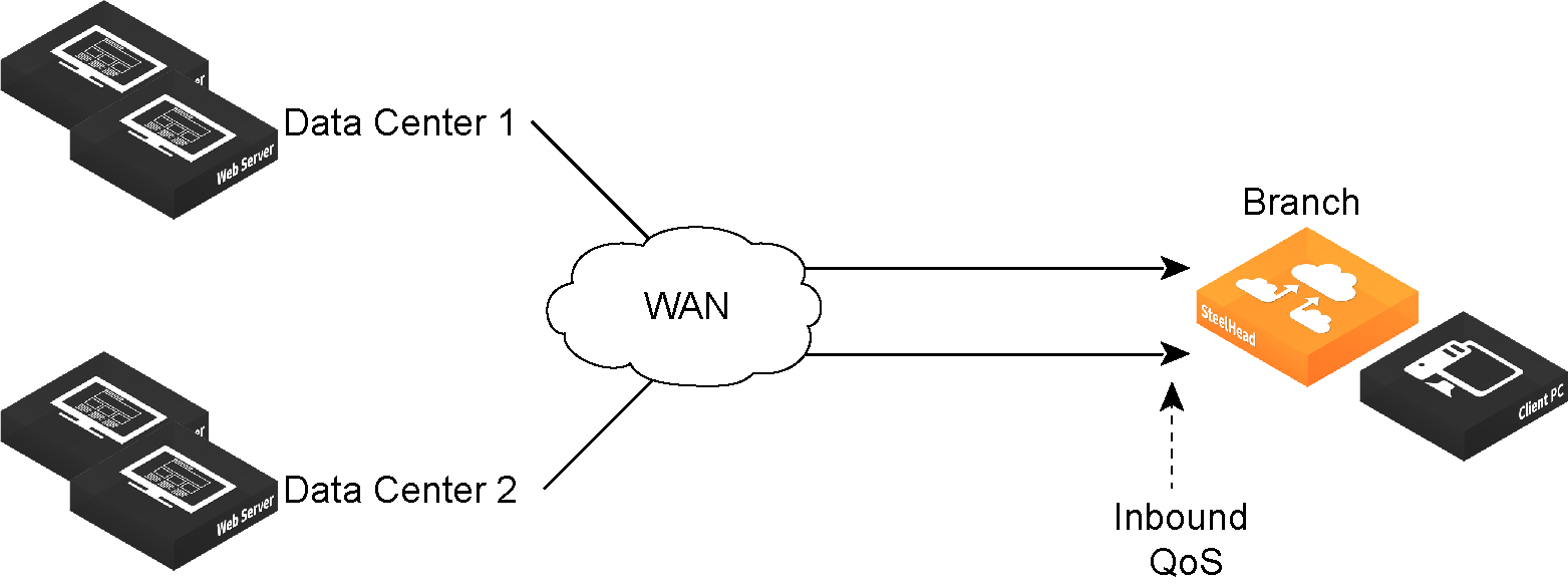
Configuring inbound QoS focuses on prioritizing types of traffic using rules and classes just like outbound QoS. The inbound configuration is separate from the outbound configuration. You define the applications on the local network and then create their corresponding shaping policies.
Inbound QoS overview

Inbound QoS applies the HFSC shaping policies to the ingress traffic. Applying policies to the ingress traffic addresses environments in which bandwidth constraints exist at the downstream location. When this condition occurs, the downstream SteelHead (where inbound QoS is enabled) dynamically communicates the bandwidth constraints to the client transmitting the traffic. The client slows down the throughput and the traffic adheres to the configured inbound QoS rule. Inbound QoS, just like outbound QoS, isn’t a dual-ended SteelHead solution. A single SteelHead performing traffic shaping as needed to avoid network congestion controls inbound WAN traffic on its own.
For details about the HFSC queueing technology, see
Traffic classification and the
SteelHead Deployment Guide.
How a SteelHead identifies and shapes inbound traffic
QoS rules define the types of traffic flowing into the branch office. As with outbound QoS, the rule can match the traffic based on VLAN, IP header values, TCP/UDP ports, and AFE information. As an example, you can ensure that the voice traffic on the WAN is reserved a fixed bandwidth and this traffic has a higher priority over the recreational internet traffic.
Inbound classes shape the inbound traffic. The class configuration resembles an outbound QoS class configuration. An outbound QoS configuration describes remote sites and applications. Inbound QoS describes the local services and applications and how to shape the inbound traffic.
The inbound traffic shaping configuration includes a default shaping class. The QoS scheduler applies the built-in inbound default class constraints and parameters on traffic not placed in any other class by the configured QoS rules. The default shaping class has a 10 percent minimum bandwidth allocation and a 100 percent maximum bandwidth allocation. You can’t delete the default class; however, you can change its bandwidth allocations.
Inbound QoS limitations
These limitations apply to inbound QoS traffic shaping.
•When packet-mode optimization is enabled, the QoS scheduler places UDP4 traffic into the MX-TCP class. All other traffic goes into the proper class.
•You can’t configure inbound QoS in an out-of-path deployment over a primary or auxiliary interface.
•Inbound QoS doesn’t throttle certain flows such as MX-TCP and UDP bulk traffic flows; however, it does provide bandwidth and latency reservation for them.
•There is no maximum number of inbound QoS rules in RiOS 9.0 and later. The maximum number of inbound QoS classes is 200.
For outbound QoS limit recommendations, see the SteelHead Deployment Guide.
Related topics
Path selection
You configure path selection in the Networking > Network Services: Path Selection page.
Path selection ensures the right traffic travels the right path, by choosing a predefined WAN gateway for certain traffic flows in real time, based on availability. You define a path, called an uplink, by specifying a WAN egress point and providing a direction for the egressing packets to take. This granular path manipulation enables you to better use and more accurately control traffic flow across multiple WAN circuits.
A common use of path selection is to route voice and video over an expensive, high-quality, multiprotocol label switching (MPLS) link, while offloading less time-sensitive business traffic over a less expensive internet VPN or direct internet link. Enabling internet paths makes efficient use of existing resources by taking advantage of both private and public links. Using path selection provides the right performance levels for your applications and saves on bandwidth costs by optimizing the use of available bandwidth.
The path selection WAN egress control:
•is a transparent operation to the client, server, and any networking devices such as routers or switches.
•identifies and processes both optimized and pass-through traffic.
•supports single and multiple firewalled paths (RiOS 8.6 and later).
•is compatible with all SteelHead transport modes, including fixed-target configuration.
•can be used to encrypt traffic using the secure transport service.
The SteelCentral Controller for SteelHead (SCC) and an SSL license are required to configure path selection with the secure transport service. You can’t configure path selection with the secure transport service from the SteelHead. For details, see the SteelCentral Controller for SteelHead User Guide and the SteelCentral Controller for SteelHead Deployment Guide.
Using paths to steer packets
To configure path selection, you define path selection rules to direct any application to any site.
Path selection rules direct matching traffic onto specific uplinks. Traffic is matched by a combination of application and destination site.
You can create multiple rules for a site. When multiple rules are created for a site, the rules are followed in the order in which they’re shown in the Path Selection page and only the first matching rule is applied to the site.
The network topology definition includes direct uplinks on a SteelHead. A SteelHead uses a direct uplink to steer packets to a specific gateway. The SteelHead can reach the gateway over Layer 2, so it can send packets directly to that gateway.
You configure a direct uplink using a SteelHead in-path IP address and a gateway IP address pair. For details, see
Defining a hybrid network topology. When you define path selection rules, you specify the uplink preferences for certain traffic.
You must deploy two SteelHeads using path selection to enforce the return uplink. To define the return uplink for traffic and override the original traffic uplink, you must deploy a SteelHead near the return traffic WAN junction point.
For more details on path selection, see the SteelHead Deployment Guide.
To configure path selection
1. Define your remote sites, associated subnets, uplinks for the local site, the gateway IP address, and peer IP address in the Sites & Network page. For details, see
Defining a hybrid network topology.
You don’t need to configure uplinks for the remote and default site.
2. Choose Networking > Network Services: Path Selection to display the Path Selection page.
Path Selection page
3. Select Enable Path Selection. Path Selection is disabled by default.
4. Under Path Selection Rules, click + Add a Rule.
5. Identify the traffic flow by selecting an application group or application for the Riverbed Application Flow Engine (AFE). Type the first few letters of the application in the Application/Application Group field. As you type the name of an application group or application, a menu appears and lists available applications that match the letters. Select an application from the list. The default setting is any application group or application.
6. Select a destination site from the drop-down list. The default setting is any destination site.
The Any setting combines identifications of all known configured sites, including the default site. Rather than configuring a separate identical path selection rule for every known site, select the Any setting to match the destination address of every configured site. When you select Any, path selection steers the configured application and any matching configured site, or the default site, onto the selected uplink. Using the Any setting reduces the configuration steps required, yet provides a common application steering design.
7. Select the preferred uplink for the application. You can associate up to three uplinks per traffic flow in order of priority: a primary, a secondary, and a tertiary uplink. The uplinks you select cascade from one to the next, based on availability.
8. Select an outbound DSCP marking from the drop-down list. You must select DSCP values if the service providers are applying QoS metrics based on DSCP marking and each provider is using a different type of metric.
9. Optionally, select the default action to take if all the uplinks specified in the rule are down. These settings are available even when no uplinks are selected.
–Relay - Sends the traffic unmodified out of the WAN side of whichever in-path it came in on. This is the default setting.
–Drop - Drops the packets in case of failure of all three (primary, secondary, tertiary) paths. Select this option when you don’t want the traffic to pass on any of the uplinks specified in the rule, not just the primary.
You don’t have to define default uplinks to drop specific traffic flows; however, you must enable path selection.
The default rule matches any application to any destination that doesn’t match another rule.
10. Click Save to Disk to save your settings permanently.
In QoS, you can define up to three uplinks for a rule and three DSCP values for a site. The DSCP values can steer traffic based on PBR in an upstream router.
You don’t need to restart the SteelHead to enable path selection. At this point, path selection is enabled. Path selection processes new flows after you enable it, but it doesn’t process preexisting flows.
If the primary uplink assigned to a connection becomes unavailable, the SteelHead directs traffic through the next available uplink and triggers the Path Selection Path Down alarm. When the original uplink comes back up, the SteelHead redirects the traffic back to it.
For details on the Path Selection Path Down alarm, see
Configuring alarm settings and
SNMP traps.
Validating the path selection design
Use these pages to validate your design:
•Choose Networking > Network Services: Path Selection to view the Uplink Status table. Click the uplink name for details such as number of bytes sent, peer availability, and uplink status. The table reports peers that are not actively probed due to more efficient subset probing as unknown, even though the uplink is active and healthy.
•Choose Reports > Networking: Current Connections to display the details per connection.
•Choose Reports > Networking: Interface Counters to see that the traffic in a multi-interface deployment is exiting the correct interface.
To troubleshoot, we recommend taking TCP dump traces on all WAN and LAN interfaces.
Path selection use cases
This section describes several different ways to configure path selection. For more use cases, see the SteelHead Deployment Guide.
Using an interface and next hop IP address to select an uplink
In this configuration, you have multiple uplinks from the SteelHead to the remote data center. The SteelHead selects which uplink to use. For each application, you define the primary uplink as a combination of the outgoing interface (wan0_0 or wan0_1) and the next hop IP address. The system must send the probe packets over the exact uplink that the data packets take.
Path selection by relay interface and next hop IP address
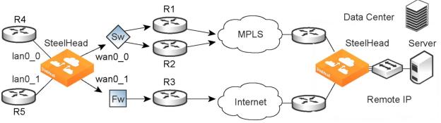
You can define this type of configuration in one of these ways:
Define the uplinks using only the relay interface
In this configuration, you define a primary uplink by specifying the wan0_0 interface and the secondary uplink as the wan0_1 interface. Suppose that the SteelHead selects the primary uplink for the application. In this case, it doesn’t matter whether it sends the packet to path 1 or path 2. In both cases, the SteelHead selects the MPLS uplink.
While probing for the remote IP address from wan0_0, the probe packets use either R1 or R2. The SteelHead can’t monitor both uplinks because it doesn’t know about them. Because it monitors only one uplink, it ensures that all data packets are also sent over that uplink. Assuming that the probe packets are being sent to the remote IP through R1, it can’t use uplink 2 to send data packets toward the server, because this uplink might be down. The SteelHead doesn’t route data packets, but simply uses the next hop learned by probing.
In the case of the secondary uplink, all packets are sent through uplink 2 so there’s no confusion.
Define the uplinks using an interface and the next hop IP address
In this configuration, you specify the next hop as well as the relay interface to use for a given uplink. This is the simplest case, because the SteelHead doesn’t need to learn anything during probing. The SteelHead doesn’t need to route data packets, because they use the next hop specified in the configuration. The SteelHead sends the packets out of the configured relay.
Path selection limitations
•You can’t base a path selection on VLANs.
•You can’t use a wildcard for the relay interface in the path definition. For example, you have to specify a relay interface for a path if you aren’t using PBR.
•You can’t use VLAN transparency for connections rerouted by path selection.
•You can’t configure LAN-side path selection.
•Path selection doesn’t handle ricochet of probe packets across relay interfaces.
•Path selection doesn’t support L2 WANs.
•Fully transparent inner connections might require connection forwarding.
•Path selection doesn’t support IPv6 connections or packet-mode flows.
•You must not install any downstream appliance that does source MAC learning a hop away from the WAN side of the SteelHead. Path selection updates a source MAC address of a packet to that of the relay being used to transmit it (IP addresses are unchanged). If source MAC learning is enabled on a downstream SteelHead that is present at next hop, the packets destined to the original source are updated with the MAC address of the SteelHead. When processing the packet, the SteelHead detects that the destination MAC address is that of itself and sends the packet up its stack instead of relaying it forward.
•Path selection doesn’t support WCCP unless it’s in DSCP-only mode.
•The SteelHead never takes on the router role or the role of a default gateway. Because path selection is transparent, you don’t have to make network design changes to accommodate path selection design.
•Path selection doesn’t react to path selection rule changes for long-lived, locally originated connections such as OOB or connection forwarding cluster and neighbor connections until you restart the optimization service.
•You can’t use path selection with single-ended SCPS connections.
•Path selection doesn’t support EtherChannel.
Related topics
Configuring path selection in a SteelHead Interceptor cluster
You can use path selection in SteelHead Interceptor deployments using the SCC to manage all Interceptors in one centralized location. You can manage Interceptors as:
•individual appliances.
•part of a SteelHead and Interceptor cluster.
RiOS 9.1 extended path selection to operate in SteelHead Interceptor cluster deployments, providing high-scale and high-availability deployment options. A SteelHead Interceptor cluster is one or more SteelHead Interceptors collaborating with one or more SteelHeads to select uplinks dynamically.
SteelHeads select uplinks based on path selection rules and network conditions and instruct a SteelHead Interceptor to steer the WAN-bound packets to the chosen uplink. A SteelHead Interceptor redirects all connections that need to be path selected to the SteelHead for the lifetime of the connection, including UDPv4 and TCPv4 optimized and unoptimized connections.
For details on using an SCC to configure SteelHead Interceptors, see the SteelCentral Controller for SteelHead User Guide.
Path selection in Interceptor cluster deployment options
You can use path selection in Interceptor cluster deployments by configuring an Interceptor neighbor on a SteelHead. In RiOS 9.1 and later, you can use the SCC to manage all Interceptor configurations in one centralized location. We recommend that you use the SCC to configure Interceptor and SteelHead clusters instead of individually configuring each appliance for these reasons:
•Enables easier configuration, operation, and management because you create one rule in one place for all cluster members (load balancing rules and so on). With one rule replacing many, you reduce the possibility of introducing configuration errors.
•To operate efficiently, path selection with Interceptor clusters (PSIC) requires that cluster channels be set up between the SteelHead and SteelHead Interceptor appliances. Cluster channels are traditionally configured on the SteelHead. In RiOS 9.2, you can now enable the PSIC auto-channel configuration feature using the SteelCentral Controller (SCC) to configure the cluster channels and then push the configuration to the appliances. No additional configuration tasks are required.
•You can create a graphical representation of your particular topology.
For details on using the SCC to configure path selection on Interceptors, see the SteelCentral Controller for SteelHead User Guide, the SteelHead Interceptor Deployment Guide, and the SteelHead Interceptor User Guide.
Configuring path selection on a SteelHead in an Interceptor cluster
When configuring uplinks on the SteelHead for path selection in an Interceptor cluster, the uplink gateway need not be a Layer 2 hop away from the SteelHead, but it must be a Layer 2 hop away from one or more Interceptors in the cluster.
Each SteelHead must be aware of which Interceptor it can use to reach a particular uplink. This is accomplished by configuring a channel that acts as an overlay tunnel between the SteelHead and the Interceptor and allows the SteelHead to reach an uplink. One or more channels must be configured for every uplink. After the SteelHead has this information, RiOS uses the Riverbed encapsulation protocol (RBEP) when communicating with an Interceptor neighbor.
Path selection with Interceptor cluster deployments assumes that:
•every WAN edge gateway in the network must be defined in the uplink configuration on the SteelHead, and at least one Interceptor must be a Layer 2 hop away from each of those uplink gateways.
•every packet to or from such an uplink gateway passes at least one Interceptor in the cluster.
•the uplink gateway doesn’t ricochet any WAN-bound packets toward the LAN, and the SteelHead must have an accurate local site subnet configuration so that the LAN-bound traffic isn’t path selected.
Adding an Interceptor as a SteelHead neighbor requires an optimization service restart, and enabling path selection on a SteelHead also requires an optimization service restart. You can avoid the second optimization service restart on the SteelHead by configuring path selection on all Interceptors in the cluster and then following the procedures in this section. All Interceptors in the cluster must be running version 5.0 or later.
To configure a SteelHead as part of an Interceptor cluster
1. You must enable connection forwarding multi-interface support to use path selection in an Interceptor cluster. Choose Networking > Network Integration: Connection Forwarding.
2. Select Enable Connection Forwarding.
3. Select Multiple Interface Support.
4. Under Neighbor Table, select Add a New Neighbor and add the IP address of the Interceptor. For details, see
To add a new neighbor.
Repeat this step for every Interceptor in the cluster.
5. Click Restart Services.
To configure path selection on a SteelHead
1. Choose Networking > Topology: Sites & Networks.
2. Define your network and your local and remote sites, and enable path selection. These changes don’t require an optimization service restart if you configure the Interceptor prior to this step. The local site requires local subnets and the uplinks. The remote site requires the remote subnet and the remote SteelHead peer. You don’t need to configure uplinks for the remote site. For details, see
Defining a hybrid network topology.
Path selection requires compatible configurations on all appliances in the cluster. When path selection is enabled on an appliance in the cluster while not enabled on another, the system considers the cluster to be incompatible and raises the Cluster Neighbor Incompatible alarm. This alarm provides the reason for the incompatibility and lists the incompatible Interceptors.
The incompatible appliances are also disconnected from each other, resulting in the Multiple Interface Connection Forwarding alarm. This alarm lists the disconnected appliances.
To configure a channel
1. Choose Networking > Network Services: Path Selection Channels. When the SteelHead has an Interceptor neighbor configured and connected, the Path Selection Channels menu option appears.
2. Under Channel Settings, define a channel as described in this table.
Control | Description |
Add a New Channel | Displays the controls to define a channel. |
Gateway IP Address | Specify the IP address of an uplink that is Layer 2 reachable by at least one interface on an Interceptor appliance. |
Interface | Select a relay interface over which the SteelHead reaches the uplink. This interface should be the same in-path interface used for the uplink configuration for the Gateway IP Address in the local site. |
Neighbor IP Address | Specify the IP address of an Interceptor in-path interface that is a Layer 2 hop away from the Gateway IP Address. |
Timeout | Optionally, specify how much time, in seconds, elapses before the system considers the channel to be unavailable. The default value is 2 seconds. Path selection uses ICMP pings to probe the channels. If the ping responses don’t make it back within this timeout setting and the system loses the number of packets defined by the threshold value, it considers the channel to be down. |
Threshold | Optionally, specify how many timed-out probes to count before the system considers the channel to be unavailable. The default is 2 failed packets. This value also determines how many probes the system must receive to consider the channel to be available. Path selection uses ICMP pings to monitor channel availability. If the ping responses don’t make it back within the probe timeout and the system loses the number of packets defined by this threshold, it considers the channel to be down. |
Add | Adds the channel to the channel table. The Management Console redisplays the channel table and applies your changes to the running configuration, which is stored in memory. The channel table displays the configuration parameters apart from the channel status and the paths on which the channels are active. |
Remove Selected Channel | Select the check box next to the name and click Remove Selected Channel. |
Path selection limitations for SteelHeads in an Interceptor cluster
These limitations apply to SteelHead path selection in an Interceptor cluster:
•You must enable connection forwarding multi-interface support.
•You can’t add a cluster channel when a GRE-tunneled path is in use. Existing paths must not use the GRE tunnel mode.
•Do not add a cluster channel when a secure uplink is in use.
For information on the Interceptor path selection limitations, see the SteelHead Interceptor Deployment Guide.