Installing Network Interface Cards
You can install add-on or replacement network interface cards (NICs) into 1U and 2U appliances. NIC installation procedures are different for different appliance models. NIC slot sizes, layout, and positioning can be quite different from one model to the next. Use the information in this chapter to identify your appliance model and correctly install your NICs.
Before installing NICs, ensure your appliance has the required software:
• All SteelHead Interceptor NICs require 8.0.0 software or later.
• The Four-Port 10-GbE Copper NIC and Four-Port 10-GbE DAC requires 9.10.0 software or later
• QuickAssist Technology (QAT) Compression/Acceleration card requires 9.9.2 software or later
All other NICs require 9.9.0 software or later.
For details about supported NICs, including part numbers, see
Reference: Supported NICs Matrix.For details about supported NIC configurations and slot restrictions, see
Reference: Supported Slot Configurations.Before configuring NICs, consider whether you want the NICs to fail-to-wire or fail-to-block. For details, see
About fail-to modes.About NIC interface names
The interface names for the NICs vary according to the product.
Product | Interface names |
SteelHead and Interceptor | In the product GUI and the CLI, the interface names are a combination of the slot number and the port pairs: (lan<slot>_<pair>, wan<slot>_<pair>). See
Figure: Slot locations and port numbering for 2U xx80 and 9800 appliances for 2U port labeling and numbering and . |
SteelCentral AppResponse | The interface name is a combination of the slot number and the port number within the slot: monNN_MM. Where NN is the slot number and MM is the port number within the slot. The port number is named from left to right, starting with 0. For example, mon2_0 is the left-most interface of a NIC installed in slot 2. |
SteelCentral NetProfiler | The SCNP-04280 and SCNP-04280-EX appliances do not have interface names. |
SteelCentral Flow Gateway | You can install an additional two-port 10-GbE card in the FlowGateway 02280 appliance. The two ports are named, from left-to-right: primary and aux. These ports replace the on-board ports with the same name. |
SteelCentral NetExpress | The interface names are a combination of the slot number and the port pair (mon<slot>_<pair>). |
About fail-to modes
You can configure NICs to fail-to-block or fail-to-bypass in the event of a power failure or other network disturbance. Fail-to-block reroutes traffic to a backup optimized path. Fail-to-bypass (also known as fail-to-wire) simply passes through the traffic without optimizing it.
Fail-to-block requires a redundant network path environment with a routing or switching infrastructure that can automatically divert traffic from the damaged link to the backup path. In this scenario, the active path is configured to use fail-to-block mode, and the backup path is configured to use fail-to-bypass mode. In the event of NIC failure, the LAN and WAN interfaces power down and connected routers or switches don’t detect the failed link.
These events trigger fail-to-block mode if the feature is enabled:
• Kernel crash
• Hardware failure
• Power loss
RiOS supports fail-to-block mode on all cards, including cards that don’t have hardware fail-to-block capabilities. For more details, see the SteelHead User Guide.
You can enable the fail-to-bypass mode on a per interface basis with these CLI commands:
• The no interface <interface-name> fail-to-bypass enable command sets the interface to block when there’s a failure.
• The interface <interface-name> fail-to-bypass enable command sets the interface to bypass when there’s a failure.
For more details, see the Riverbed Command-Line Interface Reference Manual.
About 2U slot and port numbering
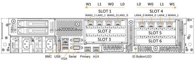
On 2U xx80 and 9800 appliances, the NIC riser assembly attaches to the motherboard between the two columns of slots. When facing the rear of the chassis:
• slots 1 to 3 are on the left, the port numbering for these cards ascends from right to left.
• slots 4 to 6 are on the right, the port numbering for these cards ascends from left to right.
The slot and port numbering for xx80 and 9800 appliances is shown in
Figure: Slot locations and port numbering for 2U xx80 and 9800 appliances. The interface names are a combination of slot and port number. For example, the interface names for slot 4, from left to right, are LAN4_0, WAN4_0, LAN4_1, WAN4_1.
Slot locations and port numbering for 2U xx80 and 9800 appliances
Installing NICs in 2U appliances
1. Power down the appliance.
2. Remove the power-supply cord.
3. Remove the cables connected to the appliance.
4. Remove the appliance from the mounting rack, if necessary.
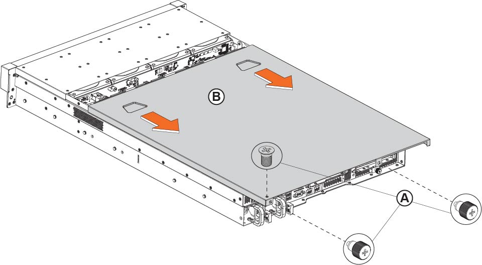
Removing the cover on 2U xx80 and 9800 appliances
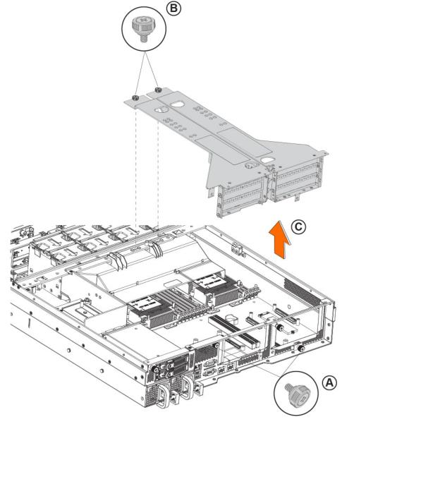
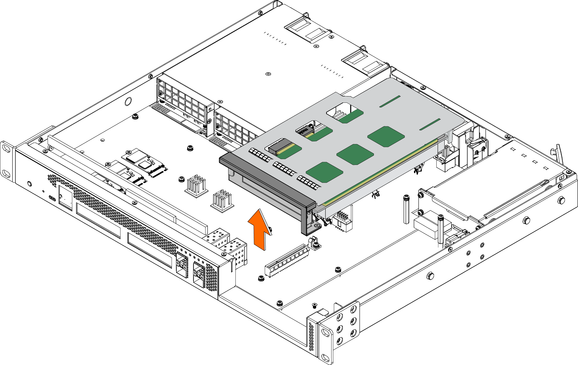
Lifting the riser brackets out of the chassis in 2U xx80 and 9800 appliances
Removing the dummy bracket
10. Hold the new card between the front bezel and the rear of the card to avoid ESD damage.
Installing the PCI riser assembly
Replacing the riser bracket in the chassis in xx80 and 9800 appliances
15. Connect the cables.
For appliances with attached storage units, reconnect the replacement NIC's SAS cable to the storage RAID cards before inserting the NIC into the slot.
16. Connect the power cords.
17. Power up the appliance and check the status lights.
About 1U 3080 slot and port numbering
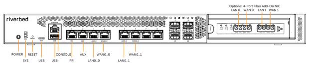
The 1U 3080 appliance supports one add-on NIC. The slot and port numbering for a 1U 3080 appliance, with an optional 4-Port Fiber NIC installed, is shown in
Figure: Slot locations and port numbering for the 1U 3080 appliance with 4-Port Fiber NIC installed.
Slot locations and port numbering for the 1U 3080 appliance with 4-Port Fiber NIC installed
Installing NICs in 3080 appliances
1. Power down the appliance.
2. Remove the power-supply cord.
3. Remove the cables connected to the appliance.
4. Remove the appliance from the mounting rack.
Removing the screws from the NIC riser bracket
8. Lift the NIC riser bracket straight up to disconnect it from the motherboard.
Removing the NIC riser bracket
9. Turn over the NIC riser bracket.
Turning over the NIC riser bracket
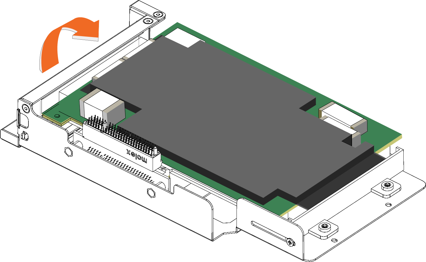
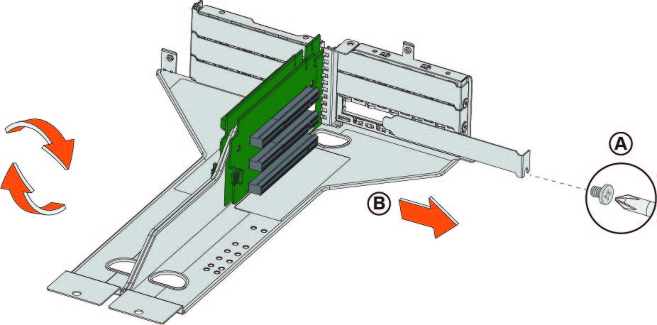
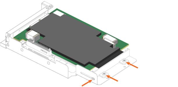
10. To replace an existing NIC, loosen the three screws that secure the card and press the bracket toward you.
Loosen the three screws and press the bracket toward you
11. Slide the NIC out of the pin connector and gently lift and pull the card away from the front of the card holder to remove it.
Removing the card from the pin connector
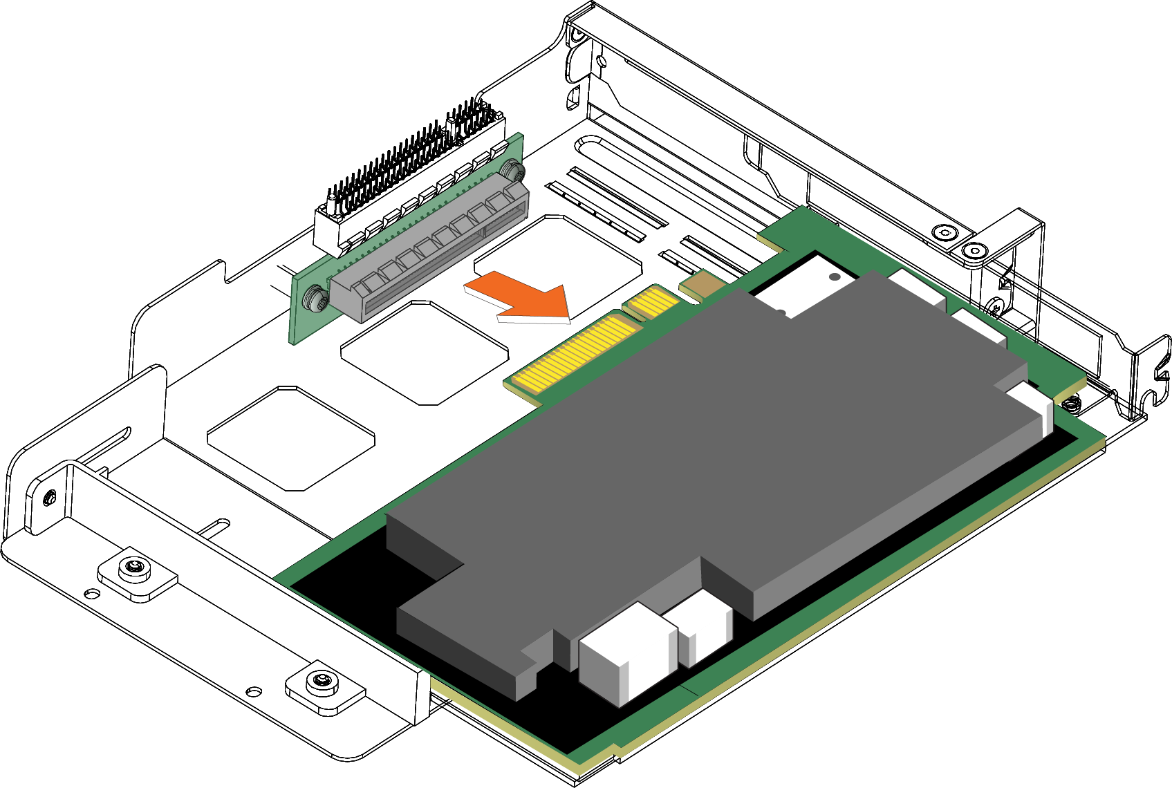
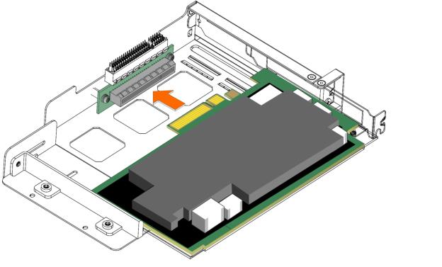
12. Hold the new NIC between the front bezel and the rear of the card to avoid ESD damage.
13. Slide the NIC into the card holder.
Installing the new NIC
14. Screw the faceplate into the holder to secure the add-on card.
Securing the faceplate
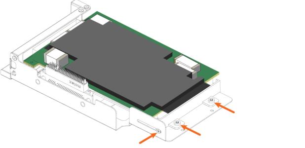
Make sure the NIC is seated properly in the pin connector. If it isn’t seated properly, the card won’t function properly.
15. Press the bracket on the right side of the card holder toward you to position the card in the holder.
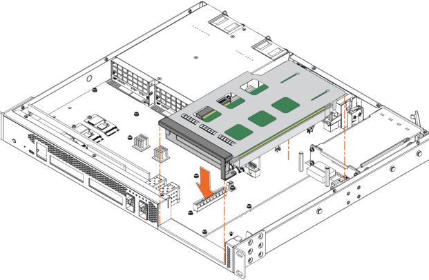
16. Turn the card holder over.
17. Press the card cover straight down into the motherboard pin connector. Make sure the card is completely inserted into the motherboard.
Inserting the PCIe card holder into the motherboard
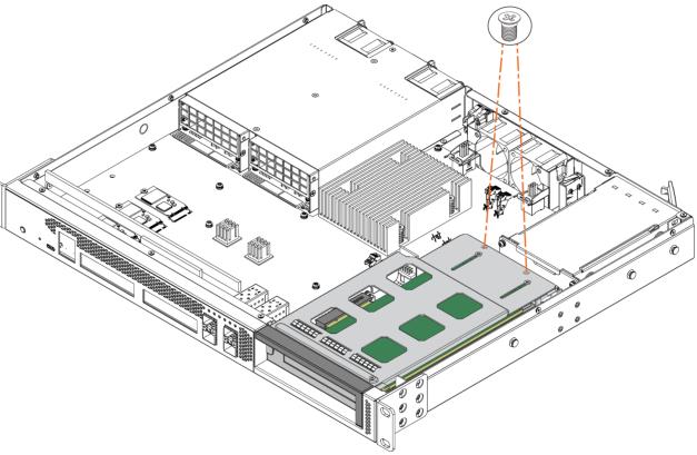
18. Secure the NIC riser bracket with the two screws.
Securing the NIC riser bracket
19. Replace the cover on the chassis. For details, see
Step 5.
20. Connect the power cords.
21. Connect the cables.
22. Power up the appliance and check the status lights.
For details on the status lights, see Reference: NIC Status Lights.
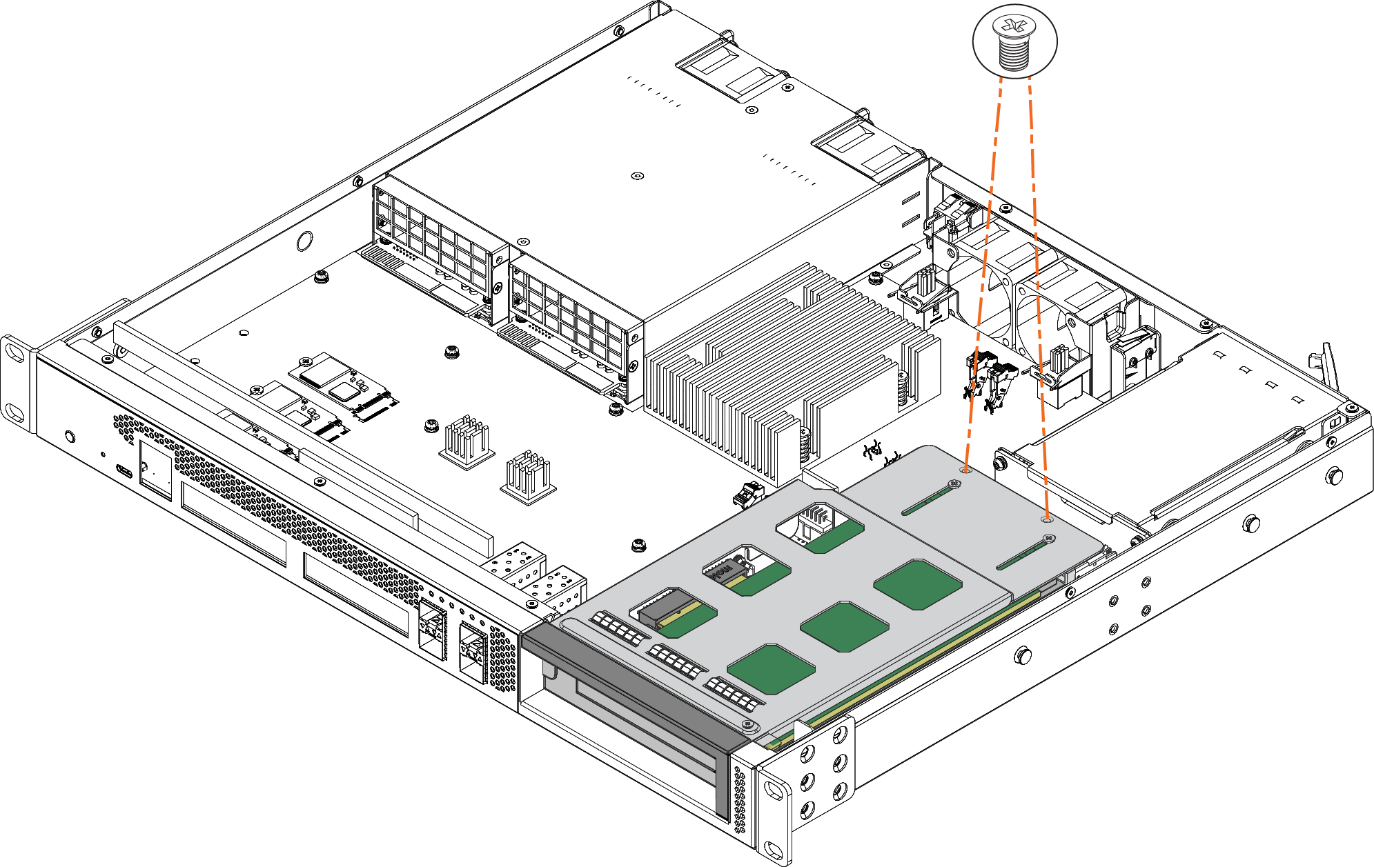
About 1U 2180 slot and port numbering
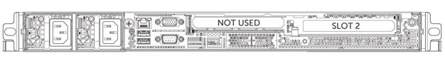
The 1U 2180 appliance supports one add-on NIC, installed in slot 2. The slot locations on the front of the 1U 2180 appliance are shown in
Figure: Slot locations for the 1U 2180 appliance.
Slot locations for the 1U 2180 appliance
Installing NICs in 2180 appliances
This section describes how to install NICs in 2180 appliances.
1. Power down the appliance.
2. Remove the power-supply cord.
3. Remove the cables connected to the appliance.
4. Remove the appliance from the mounting rack, if necessary.
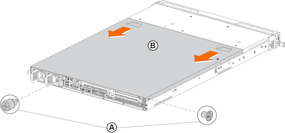
5. To remove the cover from the appliance, loosen the screw on the back of the appliance, and remove the screw on the right side of the appliance (
Step 6‑18, letter A), and slide the appliance straight back (
Step 6‑18, letter B).
Removing the cover on the 2180 appliance
6. Unscrew the two screws securing the riser to the chassis.
Removing the NIC riser
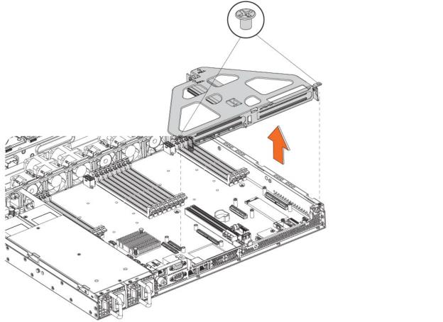
7. Lift up to remove the riser from the chassis.
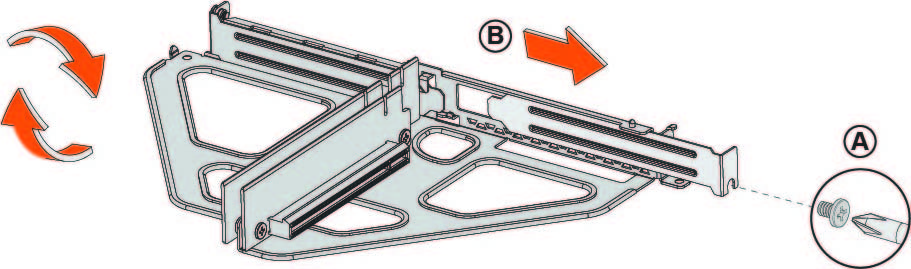
8. If you are replacing an existing card, carefully remove the screw and pull the card from the riser.
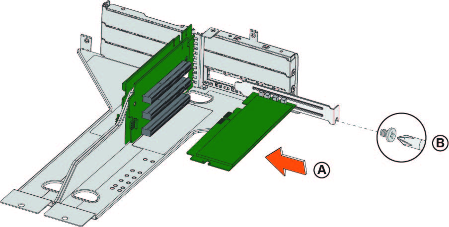
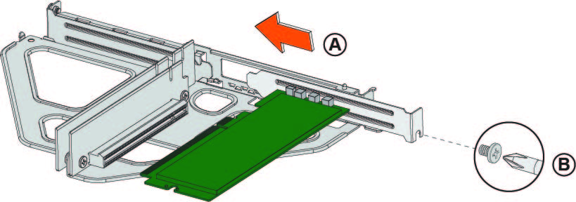
Removing the dummy bracket
10. Hold the new card between the front bezel and the rear of the card to avoid ESD damage.
11. Insert the add-on card into the riser (see
Step 6‑21, letter A) and secure it with the screw (see
Step 6‑21, letter B). Make sure the NIC bracket is latched into the riser and the pins are in the slots. If they aren’t seated properly, the cards don’t function.
Inserting the card into the riser card bracket
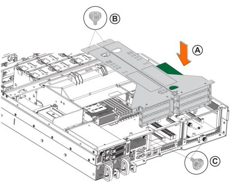
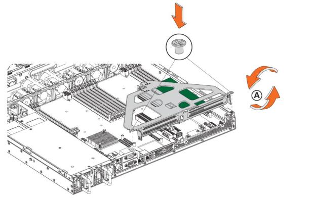
Inserting the riser card bracket into the chassis
13. Replace the cover on the chassis.
Do not secure the rear side screw; it will prevent you from opening the cover when the appliance is installed in a rack.
14. Connect the power cords.
15. Connect the cables.
16. Power up the appliance and check the status lights.
Enabling 10-GbE NICs in the 4280-DP and 2280 appliances
For the Two-Port 10-GbE NIC to function correctly in the NetProfiler 4280-DP and SteelCentral Flow Gateway 2280 appliances, you must disable the 1-GbE Primary and AUX ports and enable the 10-GbE NIC Primary and AUX interfaces.
These instructions apply only to the Two-Port 10-GbE Fiber SFP+ NIC (NIC-1-010G-2SFPP) installed in the NetProfiler 4280-DP and Flow Gateway 2280 appliances.
2. Connect to the Flow Gateway 2280 or NetProfiler 4280 base appliance using the console port. (Since you are modifying the appliance interfaces, we recommend you connect via the console port rather than SSH.)
3. Log in to the appliance as user mazu, using the password set for the device.
4. To verify that the 1-GbE NIC is present but not enabled, run this command:
sudo mazu-reconfig --get --use-addon-nic
The system returns:
found=true, enabled=false
5. If bonding of the 1-GbE interfaces is currently enabled, run the following command, otherwise, go to
Step 6.
sudo mazu-reconfig --set --bond-dp-interfaces false
Do not perform this step if you are enabling the 10-GbE NIC interface in the Flow Gateway 2280 appliance.
6. To enable the 10-GbE NIC interfaces, run this command:
sudo mazu-reconfig --set --use-addon-nic true
7. Reboot the appliance.
The 10-GbE NIC interfaces are now enabled and configurable as Primary and AUX in the web UI or the CLI. The 1-GbE NIC Primary and AUX ports are disabled by this process.
Verifying NIC installation
1. Connect to the SteelHead CLI. For detailed information, see the Riverbed Command-Line Interface Reference Manual.
2. Enter enable mode. At the system prompt, enter the following command:
amnesiac > enable
amnesiac #
3. Verify that the NIC is correctly installed.
For example, to verify the add-on cards on a SteelHead, at the system prompt enter the following command:
amnesiac # show hardware all
You can run the in-path reset-iface command in configuration mode to reset the main interface and recognize all ports.