Managing Interceptor Clusters
You manage Interceptor clusters under Manage > Topology: Clusters. Appliance clusters are sets of appliances collaborating to provide optimization in complex architectures. Clusters both distribute load across multiple appliances and provide high-availability failover capabilities. The SCC enables you to configure and manage clusters in a unified way.
Interceptors work in conjunction with SteelHeads. The topology you choose for your appliances defines the configurations of the Interceptor.
You configure Interceptors that aren’t in clusters the same way you configure SteelHeads. You define policies and apply them to a single Interceptor or groups of Interceptors.
We recommend that you use the SCC to manage appliance clusters for these reasons:
• Enables easier configuration, operation, and management—Allows for fewer errors when you create one rule in one place for all cluster members (load-balancing rules and so on). For detailed information, see the SteelHead Deployment Guide.
• Enables creation of a graphical representation of a particular topology—With the configuration wizard, you can create a graphical representation of your topology. We recommend that you use the configuration wizard to configure Interceptor and SteelHead clusters instead of individually configuring each appliance.
The SCC supports IPv6 addresses in load-balancing and in-path rules. The SCC doesn’t support VLAN segregation in Interceptor 4.0 and later. For details about the Interceptor, see the SteelHead Interceptor Deployment Guide or the SteelHead Interceptor User Guide.
Adding a cluster using the wizard
You define a cluster under Manage > Topology: Clusters. A configuration wizard guides you through the initial configuration of a cluster. After you run the wizard, you can customize additional appliance cluster settings, such as modifying the topology or adding Interceptors or SteelHeads. You can add up to four path clusters using the configuration wizard.
Before configuring the system topology, read the deployment information available in the SteelHead Interceptor Deployment Guide.
The cluster configuration can automatically generate certain policy pages for appliances in the cluster.
Click + Add a New Cluster to expand the page, and then click + Add a New Cluster to expand the page. Click Launch Cluster Configuration Wizard to launch the wizard and display the Welcome page, and then click Next to display the Basic Cluster Settings page. These configuration options are available:
Cluster Name
Specifies the name of the cluster.
Comments
Provides a description to help you administer the cluster. Descriptions must not use any character other than letters, numbers, underscore, space, or backslash (directory separator).
Connection Forwarding Settings
• Optimize Connections When Connection Forwarding Interceptor Not Connected—Select to configure an optimization cluster with other Interceptors in the network. To enable your neighbor, SteelHeads must have the in-path neighbor failure feature enabled.
• Enable IPV6 Connection Forwarding—Enables Connection Forwarding in IPv6 mode. Selecting this option disallows the use of IPv4 addresses for neighbors.
Connection forwarding defines how the appliance communicates with the other Interceptors or appliances in the communication list. For details about connection forwarding settings, see the SteelHead Interceptor User Guide.
Click Apply & Continue to display the Topology Settings page. These configuration options are available:
Select Topology
Specifies the topology you want to deploy:
• 1 path (maximum 2)
• 2 paths (maximum 4)
• 3 paths (maximum 6)
• 4 paths (maximum 8)
If you’re using multiple Interceptors, configure them as part of the cluster.
For detailed information about topology settings, see the SteelHead Interceptor Deployment Guide.
Add Interceptors
Specifies your Interceptors.
• Primary Interceptor—Select the primary Interceptor from the drop-down list.
• Failover Interceptor—Optionally, select a failover Interceptor when there are pairs of serially connected Interceptors.
For failover you deploy two Interceptors physically in-path on all of the same physical links, and each appliance is configured to act as a backup for the other appliance for the same network links. If one appliance goes down or needs maintenance, the failover appliance redirects the connections over those links. For details about configuring failover, see the SteelHead Interceptor User Guide.
Click Next to display Other Topology Settings page. These configuration options are available:
Path labels
Specifies a unique name for the path label. Path labels must use characters that are alphanumeric, underscore, hyphen, or spaces.
Interceptor labels <path>
Specifies a unique name for each selected Interceptor.
Click Apply & Continue to display the Add SteelHeads page, and then select the SteelHeads you want to add to the cluster and click Next to display the SteelHeads Labels page. Specify a unique label for each SteelHead, and click Apply & Continue to display the Summary page. Click Show Cluster Summary to review a summary of your configuration settings. Optionally, click the links on the Summary page to configure in-path and load-balancing rules. Click Close to close the wizard. The cluster is displayed in the clusters table.
After the new cluster is created, click
Run cluster wizard to make any changes to the settings, including the cluster name. For details about editing a cluster, see
Configuring path selection on Interceptor clusters.Configuring cluster in-path rules
You can configure cluster in-path rules under Manage > Appliances: Clusters. Click the cluster name to expand the page and display the cluster tabs, and then select the Cluster Pages tab to expand the page.
Select Inpath Rules (Interceptor) to display the Editing Cluster: <cluster name>, Inpath Rules (Interceptor) page.
Configuring in-path rules
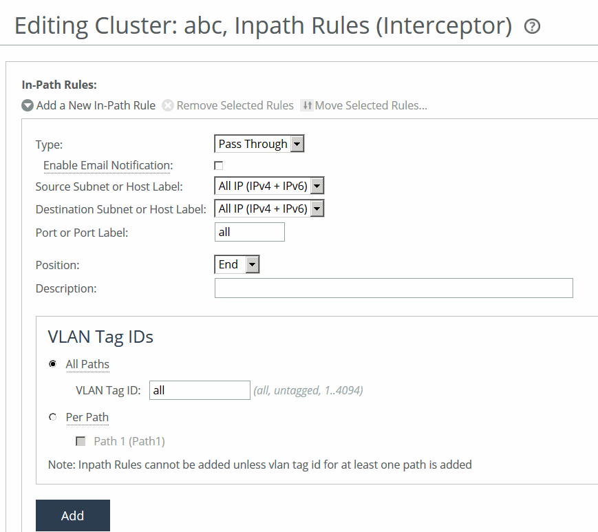
You can also select the cluster name and page to edit at the top of the Editing Cluster: <cluster name>, Inpath Rules (Interceptor) page at the top of the page.
These configuration options are available:
Type
Specifies the type of rule:
• Redirect—Redirects locally initiated TCP connections to be optimized by a SteelHead. Typically, you configure a redirect rule for source and destination addresses and ports you want to optimize in the Riverbed system. A separate set of load-balancing rules determines the SteelHead to which the connection is to be redirected.
• Passthrough—Allows the SYN packet to pass through the SteelHead unoptimized. No optimization is performed on the TCP connection initiated by this SYN packet. You define pass-through rules to exclude subnets from optimization. Traffic is also passed through when the SteelHead is in bypass mode. (Pass through of traffic might occur because of in-path rules or because the connection was established before the SteelHead was put in place or before the optimization service was enabled.)
• Discard—Drops the SYN packets silently. The SteelHead filters out traffic that matches the discard rules. This process is similar to how routers and firewalls drop disallowed packets: the connection-initiating device has no knowledge that its packets were dropped until the connection times out.
• Deny—Drops the SYN packets, sends a message back to its source, and resets the TCP connection being attempted. Using an active reset process rather than a silent discard allows the connection initiator to know that its connection is disallowed.
Enable Email Notification
Periodically sends an email reminder to evaluate in-path pass-through rules. Frequently, pass-through in-path rules are created as a temporary workaround for an acute problem. These rules often end up becoming permanent because the administrator forgets to remove them. This field is active only when you specify a pass-through rule. You can’t create notifications for other types of rules. By default, this option is enabled. Notifications are sent if one pass-through rule has this value enabled, even if other pass-through rules have this value disabled. Email is sent every 15 days.
The
Email Settings: Send Reminder of Pass-through Rules via Email option must also be enabled for SteelHead policies for notifications to be sent. For details, see
Email.
Source Subnet or Host Label
Specifies the source subnet:
• All IP (IPv4 + IPv6)—Configures a rule to apply to all source subnets.
• All IPv4—Configures a rule to apply to all IPv4 source subnets.
• All IPv6—Configures a rule to apply to all IPv6 source subnets.
• IPv4 - Configures a rule to apply to the specified source subnet. Use this format for an individual subnet IPv4 address and netmask: xxx.xxx.xxx.xxx./xx
• IPv6—Configures a rule to apply to the specified source subnet. Specify an IP address using this format: eight 16-bit hexadecimal strings separated by colons, 128-bits. For example: 2001:38dc:0052:0000:0000:e9a4:00c5:6282
You don’t need to include leading zeros. For example: 2001:38dc:52:0:0:e9a4:c5:6282
You can replace consecutive zero strings with double colons (::). For example: 2001:38dc:52::e9a4:c5:6282
• Host Label—Alternatively, specify a host label for the source subnet.
Destination Subnet or Host Label
Specifies one of these options for the destination subnet:
• All IP (IPv4 + IPv6)—Configures a rule to apply to all source subnets.
• All IPv4—Configures a rule to apply to all IPv4 source subnets.
• All IPv6—Configures a rule to apply to all IPv6 source subnets.
• IPv4—Configures a rule to apply to the specified source subnet. Use this format for an individual subnet IPv4 address and netmask: xxx.xxx.xxx.xxx./xx
• IPv6—Configures a rule to apply to the specified source subnet. Specify an IPv6 address using this format: eight 16-bit hexadecimal strings separated by colons, 128-bits. For example: 2001:38dc:0052:0000:0000:e9a4:00c5:6282
You don’t need to include leading zeros. For example: 2001:38dc:52:0:0:e9a4:c5:6282
You can replace consecutive zero strings with double colons (::). For example: 2001:38dc:52::e9a4:c5:6282
• Host Label—Alternatively, specify a host label for the source subnet.
Destination Port or Port Label
Specifies the destination port number, port label, or All.
Position
Specifies Start, End, or a rule number from the drop-down list. Interceptors evaluate rules in numerical order starting with rule 1. If the conditions set in the rule match, then the rule is applied, and the system moves on to the next packet. If the conditions set in the rule don’t match, the system consults the next rule. For example, if the conditions of rule 1 don’t match, rule 2 is consulted. If rule 2 matches the conditions, it is applied, and no further rules are consulted.
In general, list rules appear in this order:
1. Deny 2. Discard 3. Pass-through 4. Fixed-target 5. Auto-Discover
The default rule, Auto-Discover, which optimizes all remaining traffic that hasn’t been selected by another rule, can’t be removed and is always listed last.
Description
Describes the rule to facilitate administration.
Enable Rule
Enables the rule by selecting the check box.
VLAN Tag ID
Specifies a VLAN identification number from 0 to 4094, or All to apply the rule to all VLANs, or Untagged to apply the rule to nontagged connections.
Pass-through traffic maintains any preexisting VLAN tagging between the LAN and WAN interfaces.
To complete the implementation of VLAN tagging, you must set the VLAN tag IDs for the in-path interfaces that the Interceptor uses to communicate with other Interceptors.
• All Paths—Specify a VLAN identification number from 0 to 4094, or All to apply the rule to all VLANs, or Untagged to apply the rule to nontagged connections.
• Per Path—Select to configure a per path VLAN.
– Path 1—Select to specify a VLAN Tag ID from 0 to 4094, or All to apply the rule to all VLANs, or Untagged to apply the rule to nontagged connections.
Add
Adds the rule to the list.
Configuring cluster load-balancing rules
You can configure cluster load-balancing rules under Manage > Appliances: Clusters. Click the cluster name to expand the page and display the cluster tabs, and then Select the Cluster Pages tab to expand the page.
Select Load Balancing Rules to display the Editing Cluster: <cluster name>, Load Balancing Rules page.
Any changes made to the cluster configuration pages modify all the Interceptors after a cluster push.
Load-balancing rules define the characteristics by which traffic is selected for load-balancing and the availability of a LAN-side SteelHead for such traffic.
You can select the cluster name and page to edit at the top of the Editing Cluster: <cluster name>, Inpath Rules (Interceptor) page at the top of the page.
Load-balancing rules define the characteristics by which traffic is selected for load balancing and the availability of a local SteelHead for such traffic. Load balancing often involves Interceptor working together with SteelHeads.
Your load-balancing rules must account for these conditions:
• Traffic over all subnets and ports that have been selected for redirection.
• All SteelHeads you have configured as targets of redirect rules or reserved for the automatic load-balancing rule:
– If a cluster SteelHead is specified as a target for a rule, it is reserved for traffic that matches that rule and is not available to the pool used for automatic load balancing.
– If a cluster SteelHead is not specified as a target for a rule, it is available for automatic load balancing.
• Second-preference cases in which you would rather pass through traffic than tax the automatic load-balancing pool.
• IPv4 and IPv6 addresses are supported for load-balancing rules.
This table describes how the Interceptor processes load-balancing rules.
Event | Interceptor process |
|---|
Redirect rule matches and target SteelHeads are available. | Redirects traffic to a SteelHead in the target list. The Interceptor chooses a SteelHead from the list based on a connection distribution algorithm that uses peer affinity. With the peer affinity algorithm, the Interceptor has chosen the target SteelHead before. When the target list includes more than one SteelHead with peer affinity, the Interceptor chooses the SteelHead with the most affinity—that is, the appliance to which the Interceptor has forwarded the most connections. |
Redirect rule matches but none of the target SteelHeads for the rule are available. | Consults the next rule in the target list. |
Pass-through rule matches. | Passes through traffic, traversing bypass routes without optimization. Processed by service rules if path selection is enabled. |
Redirect rule matches but none of the target appliances are available; does not match a pass-through rule. No rules match. No rules specified. | The Interceptor chooses a SteelHead from the pool of SteelHeads that you have added as part of the cluster but have not assigned as targets in other load-balancing rules. The Interceptor chooses a SteelHead based on the connection distribution algorithm described above. |
About fair peering
When the Interceptor is running in standard mode, you can enable the Fair Peering feature for each load-balancing rule, including the default rule.
In VLAN segregation mode, Fair Peering v2 is enabled by default, and it cannot be disabled.
When the Fair Peering feature is enabled for a load-balancing rule, the target SteelHead cannot exceed a dynamically determined maximum number of remote SteelHeads. When that maximum is reached, peer connections are reassigned. For example, when the maximum limit for one local SteelHead is reached, the load shifts to another local SteelHead.
If a new remote SteelHead comes online, a new maximum value is dynamically computed. As a result, the Fair Peering feature ensures that all remote SteelHeads are always covered. This feature is an alternative to the default load-balancing algorithm which, when a new remote SteelHead is assigned to a local cluster, determines the appropriate local SteelHead to which the new connection should be directed.
Prior to using Fair Peering, be aware of these limitations:
• If a load-balancing rule is configured with Fair Peering enabled, the target SteelHead cannot be targeted in any other load-balancing rule.
• Load balancing can only occur among SteelHeads that are targeted by load-balancing rules with the same Fair Peering configuration.
About pressure monitoring
Pressure monitoring provides details about the health of the local SteelHeads, so that the Interceptor can better manage and balance traffic. Pressure parameters that are measured include available memory, CPU utilization, and disk load. All three pressures are treated equally, and the Interceptor sends a consolidated message to indicate one of these states: normal, high, or severe.
The value is determined as follows:
• Normal—A value of normal is assigned if all three pressures measure normal.
• High—A value of high is assigned if one or more pressures measure high but none measure severe.
• Severe—A value of severe is assigned if one or more pressures measure severe.
The SteelHeads report displays the pressure values. When the pressure monitoring feature is enabled, pressures are reported but do not necessarily affect the load-balancing functionality of the Interceptor. However, when this feature is enabled together with the Fair Peering v2 (“capacity adjustment”) option, the Interceptor implements the pressure measurements into load balancing based on the credits available in each SteelHead.
Each SteelHead is assigned credits based on its model number. The credit is equivalent to the SteelHead size used in Fair Peering. The credits determine the percentage of total load a SteelHead can handle in the cluster.
When Fair Peering v2, pressure monitoring, and capacity adjustment are enabled, the pressure data from a SteelHead determines the credits assigned to it and, as a result, the percentage of connections assigned to that SteelHead. For example, if two SteelHeads (LSH1 and LSH2) have credits 250 and 750, respectively, then the Interceptor sends 25 percent of the load to LSH1 and 75 percent to LSH2.
Specifically, when pressure data changes, SteelHead credits are affected as follows:
• Normal changing to High—SteelHead credits are reduced by 10 percent.
• Normal changing to Severe—SteelHead credits are reduced by 20 to 30 percent.
• Severe changing to Normal—SteelHead credits are restored accordingly.
Pressure readings are not polled. Rather, SteelHeads report only changes to pressure states.
About pressure monitoring and path selection
When the path selection feature is enabled, service rules specify one or more SteelHeads to which unoptimized traffic is redirected.
The Interceptor uses a hashing mechanism to select the SteelHead. The hashing mechanism takes into account the weight of the SteelHead as derived from the connection capacity of the SteelHead. This method allows a SteelHead with a larger connection capacity to receive more redirected traffic than a SteelHead with a smaller connection capacity, assuming both SteelHeads were configured in the same service rule. The hash used to pick a SteelHead from the service rule that matches the traffic flow is derived from the SRC IP address, the DST IP address, the SRC Port, and the DST Port settings of the traffic flow.
When pressure monitoring is enabled, the weight of the SteelHead is adjusted as follows:
• Normal pressure—Weight assigned is proportional to the connection capacity of the SteelHead.
• High pressure—Weight assigned is half the normal weight.
• Severe pressure—No new connections are redirected.
The weight of the SteelHead controls the number new connections and flows that will be redirected to the SteelHead. The weight does not change the connections that are already being redirected to the SteelHead.
Adding or deleting a load-balancing rule
The location of the Load Balancing Rules page depends on whether the appliance is running in standard mode or VLAN segregation mode:
• Standard mode—Choose Optimization > Optimization: Load Balancing Rules to display the Load Balancing Rules page.
• VLAN segregation mode—Load-balancing rules are configured on a per-instance basis. From the instance dashboard for a given instance, choose Load Balancing Rules under the Optimization section of the navigation bar.
In VLAN segregation mode, Fair Peering v2 is enabled by default, and it cannot be disabled. For this reason, the check box control for enabling Fair Peering v2 is not displayed on the Load Balancing Rules page when the Interceptor is running in VLAN segregation mode.
1. Display the Load Balancing Rules page in either standard mode or VLAN segregation mode.
2. Optionally, under Load Balance Settings, configure Fair Peering settings:
Enable Fair Peering v2 (Standard mode only)
Enables the Fair Peering v2 feature across all load-balancing rules. The Fair Peering v2 feature ensures that no local SteelHead exceeds a dynamically determined maximum number of remote peers.
By default, the Interceptor selects the target SteelHead on the basis of peer affinity (based on which candidate SteelHead has been used to optimize connections to or from the remote site in the past).
If you enable Fair Peering v2, this global setting overrides any traditional Fair Peering enabled on a per-rule basis.
Fair Peering v2 is supported with Interceptor version 3.0 and later and local SteelHeads running RiOS 6.1.3 or later.
Enable Pressure Monitoring
Provides more detailed information about the health of the local SteelHeads, to enable the Interceptor to better manage and balance traffic.
We recommend that you enable pressure monitoring only in conjunction with Fair Peering v2.
Enable Capacity Adjustment
Reduces the number of new connections sent to local SteelHeads for which the Interceptor determines an unacceptable pressure value. For a local SteelHead with an unacceptable pressure value, this feature artificially and temporarily reduces the capacity of the SteelHead for Interceptor load-balancing calculations. As a result of using a downward-adjusted capacity for a particular SteelHead, the Interceptor moves existing paired peers from that SteelHead to less-used SteelHeads.
The Interceptor uses the artificially reduced capacity value for that Interceptor in load-balancing calculations until the SteelHead returns to a Normal pressure value.
Enable Permanent Capacity Adjustment
Causes capacity reduction—once triggered for a local SteelHead that reaches an unacceptably high pressure value—to be permanent.
To disable permanent capacity adjustment of a SteelHead, you must issue a service restart on the Interceptor.
3. Under Load Balancing Rules, configure load-balancing rules:
Add a New Load Balancing Rule
Displays the controls to add a new rule.
Type
Specifies the type of rule from the drop-down list:
• Redirect—Configure rules of this type for traffic you want to optimize.
• Pass Through—Configure rules of this type as a second-preference rule for cases in which you want to optimize when connections are available on specified targets but, in the event that targets have reached admission control capacity, you would rather pass through traffic than tax the autobalance pool. For example, you might use pass-through rules to handle HTTP traffic on port 80.
When path selection is enabled, if traffic matches the pass-through rule, the service rule table further evaluates the traffic.
Position
Specifies one of these position from the drop-down list:
• Select Start to insert the rule at the start of the list.
• Select End to inserts the rule at end of the list.
• Select a rule number.
Enable Email Notification
Enables email notification of pass-through rules. Specify the email address using the Email page.
This option is available for pass-through rules only and is enabled by default. This option is disabled for redirect rules.
Local SteelHeads
Specifies a comma-separated list of SteelHead IP addresses to which traffic can be redirected. If a rule matches, connections are redirected to the first SteelHead in the list that has capacity for new connections. If no rule matches, peer affinity applies. If there is no existing peer affinity, the connection is redirected to the SteelHead with the least number of current connections.
The target SteelHeads are called cluster SteelHeads. The list you specify here must match the main IP addresses specified in the SteelHeads list.
If IPv6 connection forwarding is enabled, you can enter IPv6 addresses only. Use this format: x:x:x::x/xxx
Source Subnet
Specifies the subnet IP address and netmask for the source network:
• All IP (IPv4 + IPv6)—Maps to all IPv4 and IPv6 networks.
• All IPv4—Maps to 0.0.0.0/0.
• All IPv6—Maps to ::/0.
• IPv4—Prompts you for a specific IPv4 subnet address. Use this format for an individual subnet IP address and netmask: xxx.xxx.xxx.xxx/xx
• IPv6—Prompts you for a specific IPv6 subnet address. Use this format for an individual subnet IP address and netmask: x:x:x::x/xxx
Destination Subnet
Specifies the subnet IP address and netmask for the destination network:
• All IP (IPv4 + IPv6)—Maps to all IPv4 and IPv6 networks.
• All IPv4—Maps to 0.0.0.0/0.
• All IPv6—Maps to ::/0.
• IPv4—Prompts you for a specific IPv4 subnet address. Use this format for an individual subnet IP address and netmask: xxx.xxx.xxx.xxx/xx
• IPv6—Prompts you for a specific IPv6 subnet address. Use this format for an individual subnet IP address and netmask: x:x:x::x/xxx
Port or Port Label
Specifies the destination port number, port label, or All. Click Port Label to go to the Networking > Network Services: Port Labels page for reference.
If you order rules so that traffic that is passed through, discarded, or denied is filtered first, All represents all remaining ports.
From Remote SteelHeads
Specifies one of these options from the drop-down list:
• Any—Rule applies only when matching any SYN or SYN+ (behavior of load-balancing rule before peering was added).
• Probe-only—Match any packet with a probe SYN+.
• Non-probe—Match only SYN entering from the LAN side.
• IP Address—Match the given IP address when a SYN+ comes from that SteelHead.
Remote SteelHead IPs
Specifies a comma-separated list of SteelHead IP addresses (if you specify IP Address for the From Remote SteelHeads setting). You can enter either IPv4 or IPv6 addresses.
You can enter IPv6 addresses only if either the Source Subnet or the Destination Subnet map to all subnets (All IP [IPv4 + IPv6]), to all IPv6 subnets (All IPv6), or to a specific IPv6 subnet (IPv6). Otherwise, enter an IPv4 address.
VLAN Tag ID
Specifies a VLAN identification number from 0 to 4094, all to apply the rule to all VLANs, or untagged to apply the rule to nontagged connections.
Pass-through traffic maintains any preexisting VLAN tagging between the LAN and WAN interfaces.
To complete the implementation of VLAN tagging, you must set the VLAN tag IDs for the in-path interfaces that the Interceptor uses to communicate with other Interceptors.
To complete the implementation of VLAN tagging, you must set the VLAN tag IDs for the in-path interfaces that the Interceptor uses to communicate with other Interceptors.
Description
Describes the rule.
Enable Traditional Fair Peering for this Rule (Standard mode only)
Enables the traditional (v1) Fair Peering feature for the custom load-balancing rule.
If you enable traditional Fair Peering for this rule, this per-rule setting is overridden if Fair Peering v2 is enabled for load balancing.
Add
Adds the new rule to the configuration. The new rule displays in the list at the top of the page.
Remove Selected Rules
Removes the selected rule. Select the check box next to the name and click Remove Selected Rules.
The default rule cannot be removed and is always listed last.
Move Selected Rules
Moves the selected rules. Click the arrow next to the desired rule position; the rule moves to the new position.
The default rule cannot be reordered and is always listed last.
Configuring path selection on Interceptor clusters
The SCC extends path selection to operate in Interceptor cluster deployments, providing high-scale and high-availability deployment options. An Interceptor cluster is one or more Interceptors collaborating with one or more SteelHeads to select uplinks dynamically.
Path selection ensures that the right traffic travels to the right path by choosing a predefined WAN gateway for traffic flows in real-time, based on availability. In path selection, you define a path, called an uplink, by specifying a WAN egress point and providing a direction for the egressing packets to take.
SteelHeads select uplinks based on path selection rules and instruct the Interceptor to steer the WAN-bound packets to the chosen uplink. The Interceptor redirects all connections that are path selected to the SteelHead for the lifetime of the connection, including UDPv4 and TCPv4 optimized and unoptimized connections.
Path selection requires compatible configurations on all appliances in the cluster. When path selection is enabled on an appliance in the cluster while not enabled on another, the system considers the cluster to be incompatible and raises an alarm on the SteelHead. This alarm provides the reason for the incompatibility and lists the incompatible Interceptors.
Configuring path selection in cluster deployments
Before you configure path selection in a cluster deployment, these prerequisites must be met:
• You must be using Interceptor 5.0 or later, RiOS 9.1 or later on the SteelHead, and SCC 9.1 or later.
• You must enable connection-forwarding multi-interface support on each Interceptor and each SteelHead.
• You must make sure that the WAN router doesn’t ricochet packets destined for a remote destination. That is, configure the WAN router to send packets to the WAN (to prevent WAN-bound packets from ricocheting through the LAN).
• You must configure the appropriate subnet-side rules on each SteelHead.
• You must define the accurate subnet in the local site on each SteelHead.
• You must enable fair-peering v2 (FPv2) on each Interceptor.
• The Interceptor must be Layer-2-adjacent to the WAN-edge routers.
For detailed information about path selection limitations, see the SteelHead Interceptor User Guide, the SteelHead Interceptor Deployment Guide, and the SteelHead User Guide.
Path selection push prerequisites
Path selection pushes have these requirements:
• On the SteelHead, the path selection sites and uplinks must be configured before performing a cluster push on the SCC.
• The in-path interface page on the Interceptor must be configured with the gateway IP address before you perform a cluster push.
• If path selection is disabled on all appliances in cluster, the cluster push is performed without pushing the PSIC channels.
• If path selection is disabled on SteelHeads and enabled on Interceptors in the cluster, or vice a versa, the cluster push fails because it causes connection forwarding to fail.
• If path selection is enabled on all appliances, perform the cluster push along with the PSIC channels.
You can configure path selection and path selection rules under Manage > Topology: Clusters. Click the cluster name to expand the page and display the cluster tabs, and then choose Cluster Pages > Network Services to display the Editing Cluster page.
Select Enable Path Selection and click Apply, and then click + Add a New Service Rule to expand the page.
Adding service rules
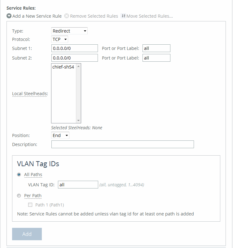
These configuration options are available:
Service Rule
Identifies the nonoptimized TCP and UDP connections used for path selection or for identifying specific traffic to be passed-through to the SteelHead. Service rules act like load-balancing rules for optimized traffic with one notable exception: the traffic is bidirectional so the source or destination isn’t important; the rules merely use the two subnets and ports. Service rules only apply to unoptimized traffic.
Type
Specifies how the system handles packets if the default uplinks go down from the drop-down list:
• Redirect—Redirects connections to a SteelHead. This is the default value. Typically, you configure a redirect rule for source and destination addresses and ports you want to optimize in the Riverbed system. A separate set of load-balancing rules determines the SteelHead to which the connection is to be redirected.
• Pass-through—Passes through traffic unoptimized. For example, you might use pass-through rules to handle HTTP traffic on port 80.
Protocol
Specifies a traffic protocol from the drop-down list:
• TCP—Specifies the TCP protocol. Supports TCP-over-IPv4 only.
• UDP—Specifies the UDP protocol. Supports UDP-over-IPv4 only.
• Any—Specifies all TCP-based and UDP-based protocols. This is the default setting.
Subnet 1/2 Port or Port Label
Specifies endpoints for subnet 1 and subnet 2 connections. Use this format: xxx.xxx.xxx.xxx./xx. You can specify all or 0.0.0.0/0 as the wildcard for all traffic.
Local SteelHeads
Specifies the local SteelHeads from the list to which traffic can be redirected. If a rule matches, connections are redirected to the first SteelHead in the list that has capacity for new connections. If no rule matches, peer affinity applies. If there is no existing peer affinity, the connection is redirected to the SteelHead with the least number of current connections.
The target SteelHeads are called cluster SteelHeads.
Position
Specifies any of these options from the drop-down list:
• Select Start to insert the rule at the start of the list.
• Select End to insert the rule at end of the list.
• Select a rule number.
The rule type of a matching rule determines which action the Interceptor takes on the connection.
Description
Provides a description of the rule.
VLAN Tag ID All Paths/Per Path
Specifies a VLAN identification number, or All to apply the rule to all VLANs, or Untagged to apply the rule to nontagged connections. Pass-through traffic maintains any preexisting VLAN tagging between the LAN and WAN interfaces.
To complete the implementation of VLAN tagging, you must set the VLAN tag IDs for the in-path interfaces that the Interceptor uses to communicate with other Interceptors.
• All Paths—Specify a VLAN identification number from 0 to 4094, or All to apply the rule to all VLANs, or Untagged to apply the rule to nontagged connections.
• Per Path—Select to configure a per path VLAN.
– Path 1—Select to specify a VLAN Tag ID from 0 to 4094, or All to apply the rule to all VLANs, or Untagged to apply the rule to nontagged connections.
Add
Adds the rule to the list.
Click Cluster Operations to display the operations you can perform on this cluster.
Pushing path selection rules
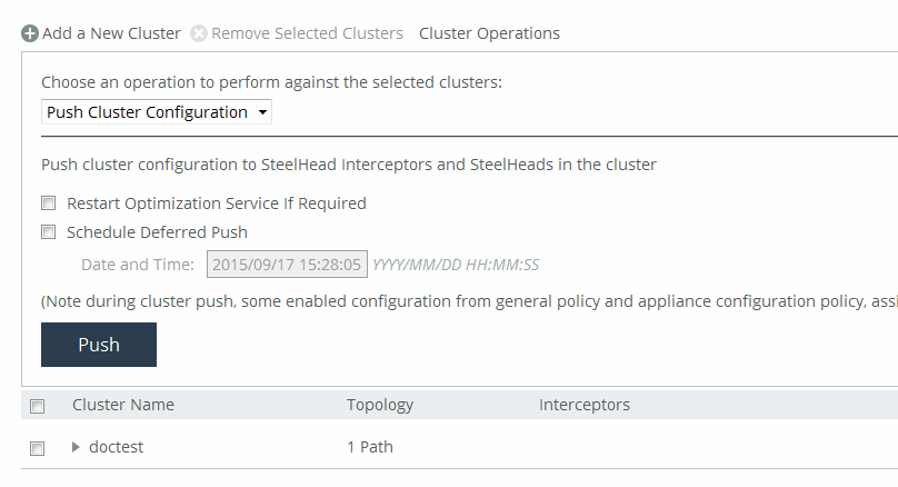
Select Push Cluster Configuration from the drop-down list. Click Push to push your settings.
Configuring channels on Interceptor clusters
To operate efficiently, path selection on Interceptor clusters requires that cluster channels are set up between the SteelHeads and Interceptors. Cluster channels are traditionally configured on the SteelHead. In SCC 9.2 and later, you can now configure the path selection channels using a site’s uplinks and push the configuration to the appliances. The path-selection cluster channel is automatically configured during the cluster push.
When configuring uplinks on the SteelHead for path selection in an Interceptor cluster, the uplink gateway need not be a Layer 2 hop away from the SteelHead, but it must be a Layer 2 hop away from one or more Interceptors in the cluster.
Each SteelHead must be aware of which Interceptor it can use to reach a particular uplink. You accomplish this by configuring a channel that acts as an overlay tunnel between the SteelHead and the Interceptor. This channel allows the SteelHead to reach an uplink. One or more channels must be configured for every uplink. After the SteelHead has this information, RiOS uses the Riverbed encapsulation protocol (RBEP) when communicating with an Interceptor neighbor.
Path selection with Interceptor cluster deployments assumes that:
• every WAN edge gateway in the network must be defined in the uplink configuration on the SteelHead, and at least one Interceptor must be a Layer 2 hop away from each of those uplink gateways.
• every packet to or from an uplink gateway passes at least one Interceptor in the cluster.
• the uplink gateway doesn’t ricochet any WAN-bound packets toward the LAN, and the SteelHead must have an accurate local site subnet configuration so that the LAN-bound traffic isn’t path selected.
• the default gateway configuration on the Interceptor can be either on the LAN side or WAN side.
• the path selection WAN gateway configuration on the SteelHead will always be on the WAN side of the Interceptor.
• if the Interceptor default gateway is on the LAN side, you will have to manually configure the PSIC channels.
For detailed information about path selection cluster channels, see the SteelHead User Guide, the SteelHead Interceptor User Guide, and the SteelHead Interceptor Deployment Guide.
To configure path selection channels on Interceptor clusters, on the SteelHead you must enable connection forwarding multi-interface support on each Interceptor and SteelHead in the cluster. For details, see the SteelHead User Guide.
On the Interceptors, enable Fair Peering v2 under load-balancing rules, and restart service on the Interceptors. For details, see the SteelHead Interceptor User Guide.
Then configure your cluster on the SCC. For details, see
Adding a cluster using the wizard. Create a site for each SteelHead in your cluster. For details, see
About sites.Define the uplinks all local sites. For local sites define the gateway IP address and the interface. There must be at least one path selection channel configured for every uplink.
Defining uplinks for cluster channels
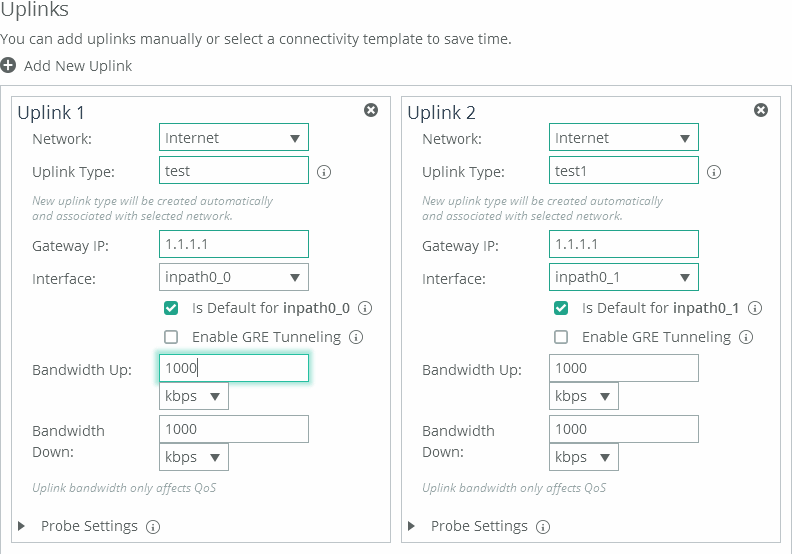
(The remote site requires the remote subnet and the remote SteelHead peer. You don’t need to configure uplinks for the remote site.)
Enable path selection on your cluster. For details, see
Configuring path selection on Interceptor clusters. Push the configuration settings for the path selection Interceptor cluster. For details, see
Pushing cluster configuration settings. Pushing the cluster configuration establishes the channel between the SteelHead, Interceptor, and the gateway IP address. For detailed information about path selection push prerequisites, see
Path selection push prerequisites.Restart the services on all the Interceptors. For details, see the SteelHead Interceptor User Guide.
Improving performance for Interceptor path selection clusters
RiOS 9.2 and Interceptor 5.5 and later support receive packet steering (RPS) to improve throughput performance on Interceptor path selection clusters. Received packet steering (RPS) distributes the traffic load across Interceptors resulting in better throughput performance. You enable RPS using the Interceptor or SteelHead CLI. This feature has these restrictions:
• Path selection must be enabled on the SteelHead and the SCC.
• Xbridge can’t be enabled.
• This feature must be configured via the Interceptor or SteelHead CLI. For detailed information, see the Riverbed Command-Line Interface Reference Guide.
Perform this task to enable RPS on path selection clusters:
1. On the SteelHead or Interceptor, connect to CLI in configuration mode. For details, see the Riverbed Command-Line Interface Reference Guide.
2. To enable RPS to improve throughput on Interceptor path selection clusters, at the system prompt enter rps enable. You can disable RPS using the no rps enable command.
3. To view RPS status, at the system prompt enter show rps.
Editing clusters
You can edit selected clusters under Manage > Topology: Clusters. Click the cluster name to expand the page and display the Edit Cluster tab, and then click the cluster name to expand the page and display the Edit Cluster tab.
Under Cluster Settings, click Run cluster wizard to display the wizard. Click Next to display the Basic Cluster Settings page. These configuration options are available:
Comments
Provides a comment to help you identify the cluster.
Rename Cluster
Renames the cluster.
New Name
Specifies the new name of the cluster.
Click Apply & Continue to display the Topology Settings page.
Fetching cluster configurations from remote appliances
You can fetch cluster configuration settings for in-path and load-balancing rules under Manage > Appliances: Clusters.
Any changes made to the cluster configuration pages modifies all the Interceptors after a cluster push.
A role-based management user with read/write permissions for the Appliance Settings: Interceptor/Cluster role must also have read/write permissions for the Appliance Management: Policy Push role to fetch cluster configurations.
Click the cluster name to expand the page and display the cluster tabs, and then select the Cluster Utilities tab to expand the page. These configuration options are available:
Select Interceptor to fetch configuration from
Specifies the Interceptor from the drop-down list. The appliance must be connected to fetch the configuration settings.
Select cluster pages to fetch
Fetches the selected page.
• Inpath Rules (Interceptor)
• Load Balancing Rules
Fetch Cluster Configuration
Fetches the selected cluster pages.
Pushing cluster configuration settings
You can push cluster configuration settings to Interceptors and SteelHeads under Manage > Appliances: Clusters.
You can also schedule the push to start at a specified date and time and restart the optimization service if required.
During cluster push, some enabled configuration settings from general policy and appliance configuration policies that are assigned to the appliance are pushed.
Cluster pushes fail on the SCC 8.6.0 through 9.2 and later when you attempt to change the IP address on the SteelHead in a cluster. You must first delete the path selection rules, load-balancing rules, and SteelHeads from the Interceptor, then push the cluster again from the SCC. For details, go to Knowledge Base article
S28086.
Click Cluster Operations to expand the page.
Pushing cluster configurations
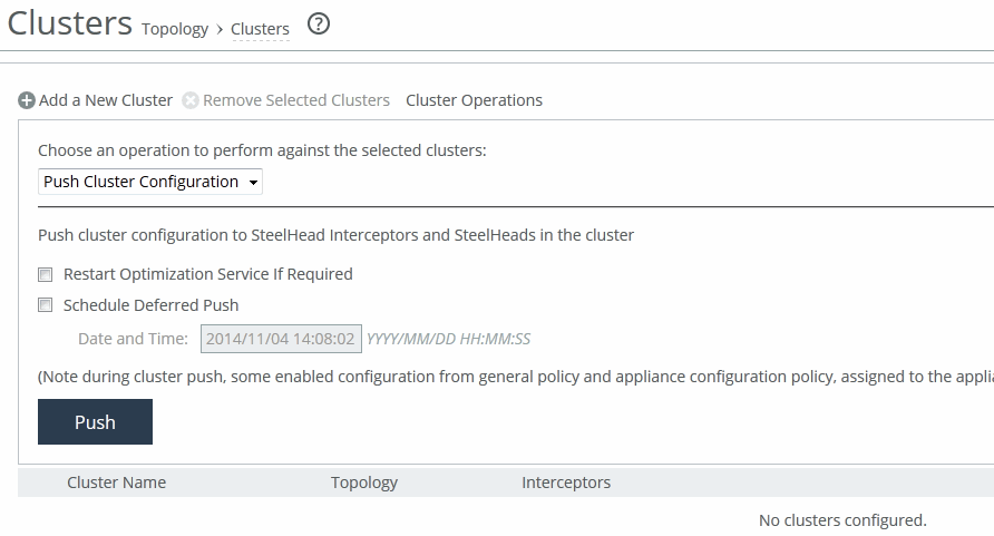
Select Push Cluster Configuration from the drop-down list. A cluster push fails if in-path interface appliance configuration for the Interceptor isn’t included in the policy push. You must configure host labels in a policy before you can perform cluster push.
These configuration options are available under Push cluster configuration:
Restart Optimization Service If Required
Restarts the optimization.
Schedule Deferred Push
Schedules the action for a later time and date. If this option isn’t selected, the action occurs the next time the appliance connects.
• Date and Time—Specify the date and time in this format: yyyy/mm/dd hh:mm:ss
Push
Pushes configuration settings to remote appliances. During a cluster push, some enabled configurations from the general policy and appliance configuration policies assigned to the appliance are pushed.
Removing clusters
You can remove selected clusters under Manage > Appliances: Clusters. Select the check box next to the cluster name you want to remove. Click Remove Selected Clusters to remove the cluster from the table.