Path Selection
You configure path selection in the Networking > Network Services: Path Selection page.
Path selection ensures the right traffic travels the right path, by choosing a predefined WAN gateway for certain traffic flows in real time, based on availability. You define a path, called an uplink, by specifying a WAN egress point and providing a direction for the egressing packets to take. This granular path manipulation enables you to better use and more accurately control traffic flow across multiple WAN circuits.
A common use of path selection is to route voice and video over an expensive, high-quality, multiprotocol label switching (MPLS) link, while offloading less time-sensitive business traffic over a less expensive Internet VPN or direct Internet link. Enabling Internet paths makes efficient use of existing resources by taking advantage of both private and public links. Using path selection provides the right performance levels for your applications and saves on bandwidth costs by optimizing the use of available bandwidth.
The path selection WAN egress control:
• is a transparent operation to the client, server, and any networking devices such as routers or switches.
• identifies and processes both optimized and pass-through traffic.
• supports single and multiple firewalled paths (RiOS 8.6 and later).
• is compatible with all SteelHead transport modes, including fixed-target configuration.
• can be used to encrypt traffic using the secure transport service.
Note: The SteelCentral Controller for SteelHead and an SSL license is required to configure path selection with the secure transport service. You can’t configure path selection with the secure transport service from the SteelHead. For details, see the SteelCentral Controller for SteelHead User’s Guide and the SteelCentral Controller for SteelHead Deployment Guide.
Using Paths to Steer Packets
To configure path selection, you define path selection rules to direct any application to any site.
Path Selection rules direct matching traffic onto specific uplinks. Traffic is matched by a combination of application and destination site.
You can create multiple rules for a site. When multiple rules are created for a site, the rules are followed in the order in which they’re shown in the Path Selection page and only the first matching rule is applied to the site.
The network topology definition includes direct uplinks on a SteelHead. A SteelHead uses a direct uplink to steer packets to a specific gateway. The SteelHead can reach the gateway over Layer 2, so it can send packets directly to that gateway.
You configure a direct uplink using a SteelHead in-path IP address and a gateway IP address pair. For details, see
Defining a Hybrid Network Topology. When you define path selection rules, you specify the uplink preferences for certain traffic.
You must deploy two SteelHeads using path solution to enforce the return uplink. To define the return uplink for traffic and override the original traffic uplink, you must deploy a SteelHead near the return traffic WAN junction point.
For path selection limits, see
Path Selection Limits.
For path selection use case examples, see
Path Selection Use Cases.
For more details on path selection, see the SteelHead Deployment Guide.
To configure path selection
1. Define your remote sites, associated subnets, uplinks for the local site, the gateway IP address, and peer IP address in the Sites & Network page. For details, see
Defining a Hybrid Network Topology.
You don’t need to configure uplinks for the remote and default site.
2. Choose Networking > Network Services: Path Selection to display the Path Selection page.
Figure: Path Selection Page
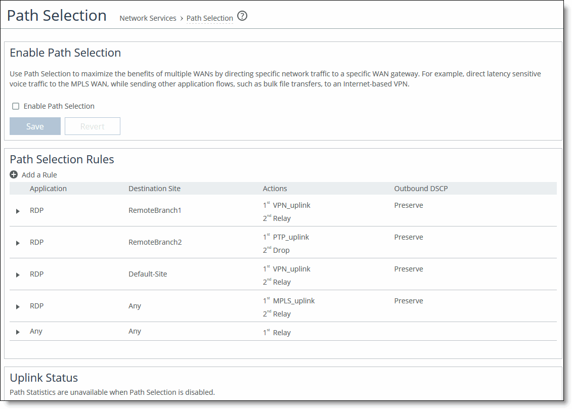
3. Select Enable Path Selection. Path Selection is disabled by default.
4. Under Path Selection Rules, click + Add a Rule.
5. Identify the traffic flow by selecting an application for the Riverbed Application Flow Engine (AFE). Type the first few letters of the application in the Application/Application Group field. As you type the name of an application, a menu appears and lists available applications that match your typing. Select an application from the list. The default setting is any application or application group.
6. Select a destination site from the drop-down list. The default setting is any destination site.
The Any setting combines identifications of all known configured sites, including the Default-Site. Rather than configuring a separate identical path selection rule for every known site, select the Any setting to match the destination address of every configured site. When you select Any, path selection steers the configured application and any matching configured site, or the default-site, onto the selected uplink. Using the Any setting reduces the configuration steps required, yet provides a common application steering design.
7. Select the preferred uplink for the application. You can associate up to three uplinks per traffic flow in order of priority: a primary, a secondary, and a tertiary uplink. The uplinks you select cascade from one to the next, based on availability.
8. Select an outbound DSCP marking from the drop-down list. You must select DSCP values if the service providers are applying QoS metrics based on DSCP marking and each provider is using a different type of metric.
9. Optionally, select the default action to take if all the uplinks specified in the rule are down. These settings are available even when no uplinks are selected.
• Relay - Sends the traffic unmodified out of the WAN side of whichever in-path it came in on. This is the default setting.
• Drop - Drops the packets in case of failure of all three (primary, secondary, tertiary) paths. Select this option when you don’t want the traffic to pass on any of the uplinks specified in the rule, not just the primary.
You don’t have to define default uplinks to drop specific traffic flows; however, you must enable path selection.
The default rule matches any application to any destination that doesn’t match another rule.
10. Click Save to Disk to save your settings permanently.
In QoS, you can define up to three uplinks for a rule and three DSCP values for a site. The DSCP values can steer traffic based on PBR in an upstream router.
You don’t need to restart the SteelHead to enable path selection. At this point, path selection is enabled. Path selection processes new flows after you enable it, but it doesn’t process preexisting flows.
If the primary uplink assigned to a connection becomes unavailable, the SteelHead directs traffic through the next available uplink and triggers the Path Selection Path Down alarm. When the original uplink comes back up, the SteelHead redirects the traffic back to it.
For details on the Path Selection Path Down alarm, see
Configuring Alarm Settings and
SNMP Traps.
Validating the Path Selection Design
Use these pages to validate your design:
• Choose Networking > Network Services: Path Selection to view the Uplink Status table. Click the uplink name for details such as number of bytes sent, peer availability, and uplink status. The table reports peers that are not actively probed due to more efficient subset probing as unknown, even though the uplink is active and healthy.
• Reports > Networking: Current Connections shows details per connection.
• Reports > Networking: Interface Counters shows that the traffic in a multi-interface deployment is exiting the correct interface.
To troubleshoot, we recommend taking TCP dump traces on all WAN and LAN interfaces.
Path Selection Use Cases
This section describes several different ways to configure path selection. For more use cases, see the SteelHead Deployment Guide.
Using an Interface and Next Hop IP Address to Select an Uplink
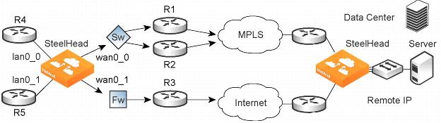
In this configuration, you have multiple uplinks from the SteelHead to the remote data center. The SteelHead selects which uplink to use. For each application, you define the primary uplink as a combination of the outgoing interface (wan0_0 or wan0_1) and the next hop IP address. The system must send the probe packets over the exact uplink that the data packets take.
Figure: Path Selection by Relay Interface and Next Hop IP Address
You can define this type of configuration in one of these ways:
Define the Uplinks Using Only the Relay Interface
In this configuration, you define a primary uplink by specifying the wan0_0 interface and the secondary uplink as the wan0_1 interface. Suppose that the SteelHead selects the primary uplink for the application. In this case, it doesn’t matter whether it sends the packet to path 1 or path 2. In both cases, the SteelHead selects the MPLS uplink.
While probing for the remote IP address from wan0_0, the probe packets use either R1 or R2. The SteelHead can’t monitor both uplinks because it doesn’t know about them. Because it monitors only one uplink, it ensures that all data packets are also sent over that uplink. Assuming that the probe packets are being sent to the remote IP through R1, it can’t use uplink 2 to send data packets toward the server, because this uplink might be down. The SteelHead doesn’t route data packets, but simply uses the next hop learnt by probing.
In the case of the secondary uplink, all packets are sent through uplink 2 so there’s no confusion.
Define the Uplinks Using an Interface and the Next-Hop IP Address
In this configuration, you specify the next hop as well as the relay interface to use for a given uplink. This is the simplest case, because the SteelHead doesn’t need to learn anything during probing. The SteelHead doesn’t need to route data packets, because they use the next hop specified in the configuration. The SteelHead sends the packets out of the configured relay.
Path Selection Limits
These limits apply to path selection:
• You can’t base a path selection on VLANs.
• You can’t use a wildcard for the relay interface in the path definition. For example, you have to specify a relay interface for a path if you aren’t using PBR.
• You can’t use VLAN transparency for connections rerouted by path selection.
• You can’t configure LAN-side path selection.
• Path selection doesn’t handle ricochet of probe packets across relay interfaces.
• Path selection doesn’t support L2 WANs.
• Fully transparent inner connections might require connection forwarding.
• Path selection doesn’t support IPv6 connections or packet-mode flows.
• You must not install any downstream appliance that does source MAC learning a hop away from the WAN side of the SteelHead. Path selection updates a source MAC address of a packet to that of the relay being used to transmit it (IP addresses are unchanged). If source MAC learning is enabled on a downstream SteelHead that is present at next hop, the packets destined to the original source are updated with the MAC address of the SteelHead. When processing the packet, the SteelHead detects that the destination MAC address is that of itself and sends the packet up its stack instead of relaying it forward.
• Path selection doesn’t support WCCP unless it’s in DSCP-only mode.
• The SteelHead never takes on the router role or the role of a default gateway. Because path selection is transparent, you don’t have to make network design changes to accommodate path selection design.
• Path selection doesn’t react to path selection rule changes for long-lived, locally originated connections such as OOB or connection forwarding cluster and neighbor connections until you restart the optimization service.
• You can’t use path selection with single-ended SCPS connections.
• Path selection doesn’t support EtherChannel.
Related Topics