Defining a Hybrid Network Topology
You define the network connectivity view in the Networking > Topology: Sites & Networks page.
RiOS 9.0 and later provide a way to define a static network topology to a configuration that is shareable between SteelHeads. The network topology definition becomes a building block that simplifies SteelHead feature configuration for path selection and QoS. You define a topology once and then reuse it as needed. The topology provides the network point-of-view to all other possible sites, including each remote site’s networks and a remotely ping-able IP address.
RiOS uses the topology definition to:
• share the remote site information between peers.
• determine possible remote paths for path selection.
• precompute the estimated end-to-end bandwidth for QoS, based on the remote uplinks.
We strongly recommend that you define topologies, push topology definitions, and distribute updates to an existing topology from a SteelCentral Controller for SteelHead to the SteelHead appliances, particularly with large scale deployments. For details, see the SteelCentral Controller for SteelHead Deployment Guide.
Topology Properties
A network topology includes these WAN topology properties:
• Networks - Define the carrier-provided WAN connections: for example, MPLS, VSAT, or Internet.
• Sites - Define the discrete physical locations on the network: for example, a branch office or data center. A site can be a single floor of an office building, a manufacturing facility, or a data center. The sites can be linked to one or more networks. The local sites use the WAN in the network definition to connect to the other sites. The default site is a catch-all site that is the only site needed to backhaul traffic. Sites are used with the path selection, QoS, and secure transport features.
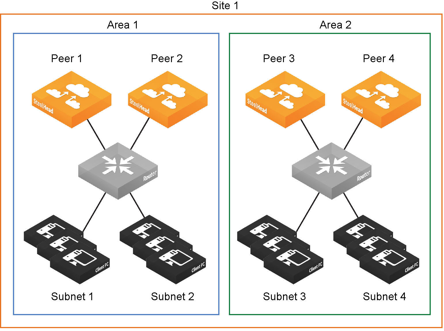
If SteelHead peers connect to subnets within a network that don’t communicate with each other, you can define an area, as shown in
Site Definition Divided into Areas. To configure areas, use the Riverbed command-line interface.
• Uplinks - define the last network segment connecting the local site to a network. You define carrier-assigned characteristics to an uplink: for example, the upload and download bandwidth and latency. An uplink must be directly (L2) reachable by at least one SteelHead or Interceptor in the local network. An uplink doesn’t need to be a physical in-path. Path selection uses only local uplinks.
Figure: Topology Overview
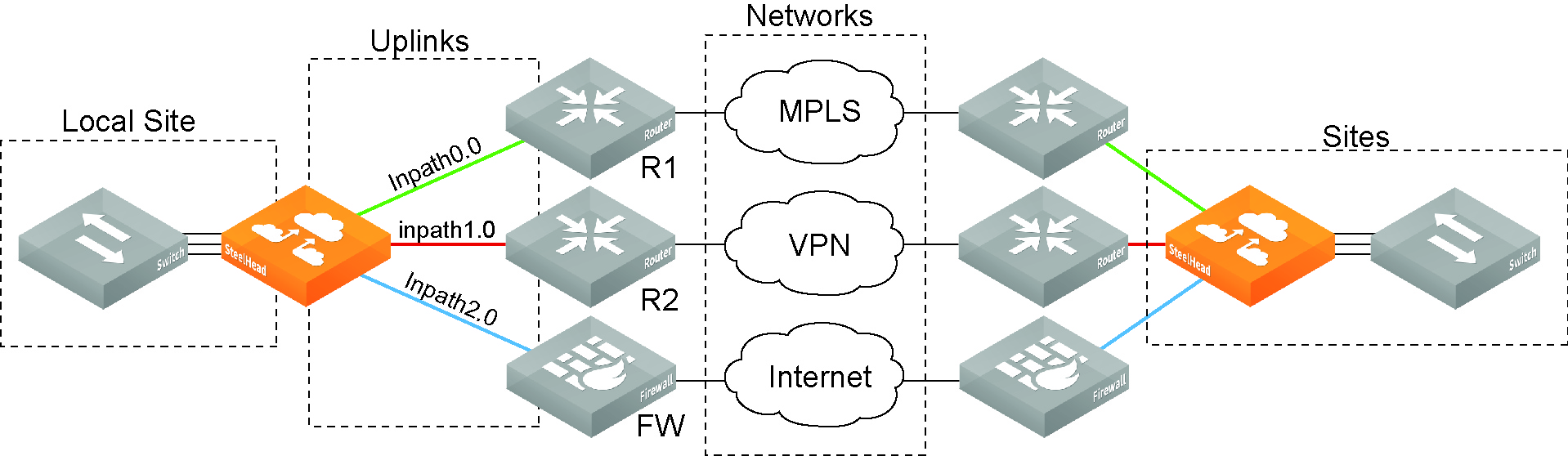
Figure: Site Definition Divided into Areas
The Sites & Networks page is central to defining networks and sites, to viewing sites with which a network is associated, changing or deleting sites, and assigning uplinks to a site.
Defining a Network
Networks represent the WAN networks that sites use to communicate with each other, such as MLPS, VSAT, or Internet.
To add a network
1. Choose Networking > Topology: Sites & Networks to display the Sites & Networks page.
The networks appear. The default network is the network to which RiOS links the default uplinks. You can’t delete the default network.
If you aren’t using path selection, you can use the default network. To configure path selection, you can edit the network for the default uplinks: for example, Default0_0 uses MPLS, while Default0_1 uses Internet.
2. Under Networks, click + Add a Network.
Figure: New Network Dialog Box
3. Specify the network name, for example, MPLS1.
4. Select public if the network represents the Internet.
You can also configure a secure network on the SCC. Secure transport uses UDP to encapsulate traffic on a public network. For details on secure transport, see the SteelCentral Controller for SteelHead User’s Guide and the Riverbed Command-Line Interface Reference Manual.
5. Click Save.
Defining a Site
You can optionally add sites to the network. A site is a logical grouping of subnets. Sites represent the physical and logical topology of a site type. You can classify traffic for each site using network addresses. Site types are typically data center, small, medium and large branch office, and so on. Sites provide the SteelHead with the IP addresses of all subnets existing within a site (this applies to nonSteelHead sites as well).
You must define local and remote sites. The site definitions include a list of IP subnets that path selection or QoS will use to identify the site. Every subnet must be globally unique, although they can overlap.
You also need to define the default site that provides a catch all for traffic not assigned to another site.
RiOS 9.0 and later determine the destination site using a longest-prefix match on the site subnets. For example, if you define site 1 with 10.0.0.0/8 and site 2 with 10.1.0.0/16, then traffic to 10.1.1.1 matches site 2, not site 1. Consequently, the default site defined as 0.0.0.0 only matches traffic that doesn’t match any other site subnets. This is in contrast to RiOS 8.6 and earlier, where you configured sites in an explicit order and the first-matching subnet indicated a match for that site.
You can associate an inbound or outbound QoS profile with a site to fine-tune the QoS behavior for each site. For details, see
Creating QoS Profiles.
The default site is a catch-all for traffic not assigned to another site that has a subnet of 0.0.0.0/0. You don’t need to add a remote site if you only have one remote site and the default site is suitable.
To add a site
1. Choose Networking > Topology: Sites & Networks to display the Sites & Networks page.
2. Under Sites, click + Add a Site.
Figure: Create a New Site Dialog Box
3. Specify the site name, for example, DCEurope.
4. Optionally, specify a subnet IP prefix for a set of IP addresses on the LAN-side, separating multiple subnets with commas.
5. Optionally, specify the SteelHead IP addresses of the peers. The site uses peers for path selection monitoring and GRE tunneling. Separate multiple peers with commas. SteelHead peers are select distinct IP addresses you choose to poll, in order, to monitor path availability or they’re the remote site at the end of a GRE tunnel. We strongly recommend that you use the remote SteelHead in-path IP address as a peer address when possible.
When you add a site in the SteelCentral Controller for SteelHead you don’t have to specify the IP addresses of the SteelHeads at each given site because the SCC dynamically adds them to the site configuration that it sends to the SteelHeads.
You can use the CLI to connect a peer to multiple areas through different interfaces. For details, see the Riverbed Command-Line Interface Reference Manual.
6. Optionally, select an inbound or outbound QoS profile to use with the site. For details, see
Creating QoS Profiles.
You don’t need to select a QoS profile for path selection.
7. Click Save.
Defining Uplinks
Configuring a network topology involves specifying uplinks. An uplink is the last network segment connecting the local site to a network. At a high level, you can define multiple uplinks to a given network. The SteelHead monitors the state of the uplink and, based on this, selects the appropriate uplink for a packet. Selecting appropriate uplinks for packets provides more control over network link use.
Remote uplinks are also important for QoS because they define the available bandwidth for remote sites. RiOS uses the specified bandwidth to compute the end-to-end bottleneck bandwidth for QoS.
You can define an uplink based on an egress interface and, optionally, the next-hop gateway IP address. You can specify different DSCP marks per uplink for a given flow, allowing an upstream router to steer packets based on the observed marking.
To monitor uplink availability; you configure the latency of the uplink (timeout) and the loss observed (threshold). Path selection uses ICMP pings to monitor the uplink state dynamically, on a regular schedule (the default is two seconds). If the ping responses don’t make it back within the probe timeout period, the probe is considered lost. If the system loses the number of packets defined by the probe threshold, it considers the uplink to be down and triggers an alarm, indicating that the uplink is unavailable.
If one uplink fails, the SteelHead directs traffic through another available uplink. When the original uplink comes back up, the SteelHead redirects the traffic back to it.
You can configure up to 1024 direct uplinks.
Defining Tunneled Uplinks
RiOS 8.6 and later include a tunnel mode to provide IPv4 generic routing encapsulation (GRE) for direct uplinks. Direct uplinks using GRE become direct tunneled uplinks. You must create direct tunneled uplinks to steer traffic over any uplink that traverses a stateful firewall between the server-side SteelHead and the client-side SteelHead.
Without GRE, traffic attempting to switch midstream to a uplink that traverses a stateful firewall might be blocked. The firewall needs to track the TCP connection state and sequence numbers for security reasons. Because the firewall has not logged the initial connection handshake, and has partial or no packet sequence numbers, it blocks the attempt to switch to the secondary uplink and might drop these packets. To traverse the firewall, path selection can encapsulate that traffic into a GRE tunnel. The most common examples of midstream uplink switching occur when:
• a high-priority uplink fails over to a secondary uplink that traverses a firewall.
• a previously unavailable uplink recovers and resumes sending traffic to a firewalled uplink.
• path selection is using the Application File Engine (AFE) to identify the traffic and doesn’t yet recognize the first packets of a connection before traversing a default uplink.
The GRE tunnel starts with a SteelHead and ends at the remote SteelHead. Both SteelHeads must be running RiOS 8.6.x or later. The tunnel configuration is local. The remote IP address must be a remote SteelHead in-path interface and the remote SteelHead must have path selection enabled. ICMP responses from the remote SteelHead use the same tunnel from which the ping is received. The remote SteelHead must also have GRE tunnel mode enabled if the user wants return traffic to go through a GRE as well.
To add an uplink
1. Choose Networking > Topology: Sites & Networks to display the Sites & Network page.
2. To add an uplink to a new site, under Sites, click +Add a Site. To add an uplink to an existing site, click Edit Site next to the site name.
3. Under Uplinks, click +Add New Uplink.
Figure: New Uplink Dialog Box
4. Specify the uplink name, for example, MPLS1. We recommend using the same name for an uplink in all sites connecting to the same network. If you later use an SCC to maintain the SteelHeads, it will group uplinks by their names to simplify the configuration of new sites. Each uplink must have a unique interface, gateway and probe DSCP setting. A topology doesn’t allow duplicate uplinks.
5. Select a network from the drop-down list.
6. Optionally, specify a gateway IP address for path selection.
7. Specify an in-path interface.
8. Optionally, click GRE Tunneling to provide IPv4 generic routing encapsulation (GRE) for direct uplinks used in path selection. Direct uplinks using GRE become direct tunneled uplinks. You must create direct tunneled uplinks to steer traffic over any uplink that traverses a stateful firewall between the server-side SteelHead and the client-side SteelHead.
Without GRE, traffic attempting to switch midstream to a uplink that traverses a stateful firewall might be blocked. The firewall needs to track the TCP connection state and sequence numbers for security reasons. Because the firewall has not logged the initial connection handshake, and has partial or no packet sequence numbers, it blocks the attempt to switch to the secondary uplink and might drop these packets. To traverse the firewall, path selection can encapsulate that traffic into a GRE tunnel.
For details on firewalled path selection deployments, see the SteelHead Deployment Guide.
9. Specify the up and down bandwidth in kilobits per second. RiOS uses the bandwidth to precompute the end-to-end bandwidth for QoS. The SteelHead automatically sets the bandwidth for the default site to this value.
The uplink rate is the bottleneck WAN bandwidth, not the interface speed out of the WAN interface into the router or switch. As an example, if your SteelHead connects to a router with a 100 Mbps link, don’t specify this value—specify the actual WAN bandwidth (for example, T1, T3).
Different WAN interfaces can have different WAN bandwidths; you must enter the bandwidth link rate correctly for QoS to function properly.
10. Optionally, click the right-arrow and specify the probe settings for path selection monitoring as described in this table.
Control | Description |
Outbound DSCP | Select the DSCP marking for the ping packet. You must select this option if the service providers are applying QoS metrics based on DSCP marking and each provider is using a different type of metric. Path selection-based DSCP marking can also be used in conjunction with PBR on an upstream router to support Path Selection in cases where the SteelHead is more than a single L3 hop away from the edge router. The default marking is preserve. Preserve specifies that the DSCP level or IP ToS value found on pass-through and optimized traffic is unchanged when it passes through the SteelHead. |
Timeout | Specify how much time, in seconds, elapses before the system considers the uplink to be unavailable. The default value is 2 seconds. RiOS uses ICMP pings to probe the uplinks. If the ping responses don’t make it back within this timeout setting and the system loses the number of packets defined by the threshold value, it considers the uplink to be down and triggers the Path Selection Path Down alarm. |
Threshold | Specify how many timed-out probes to count before the system considers the uplink to be unavailable and triggers the Path Down alarm. The default is 3 failed successive packets. This value also determines how many probes the system must receive to consider the uplink to be available. RiOS uses ICMP pings to monitor uplink availability. If the ping responses don’t make it back within the probe timeout and the system loses the number of packets defined by this threshold, it considers the uplink to be down and triggers the Path Selection Path Down alarm. |
11. Click Save.
The sites appear in a table.
The default site matches all of the traffic that doesn’t match another site.
To edit a site, click Edit Site next to a site name, modify the definition, and click Save.