About Host, Interface, and General Service Settings
Host and interface settings are usually set during the initial setup and don’t often need changes. They include settings like the hostname, DNS, and proxy.
General service settings control how the appliance’s optimization service interacts with the network. Some settings depend on your deployment type. They include:
• In-path support with options for global kickoff, Layer 4/PBR/WCCP/Interceptor support, and per-interface acceleration.
• Out-of-path support for server-side deployments only.
• Connection limits to set limits for half-open connections and max connection pool size,
• Failover settings to configure behavior in case of failure.
• Packet mode optimization, which requires in-path rules.
About host settings
Host settings are under Networking > Networking: Host Settings.
Host settings
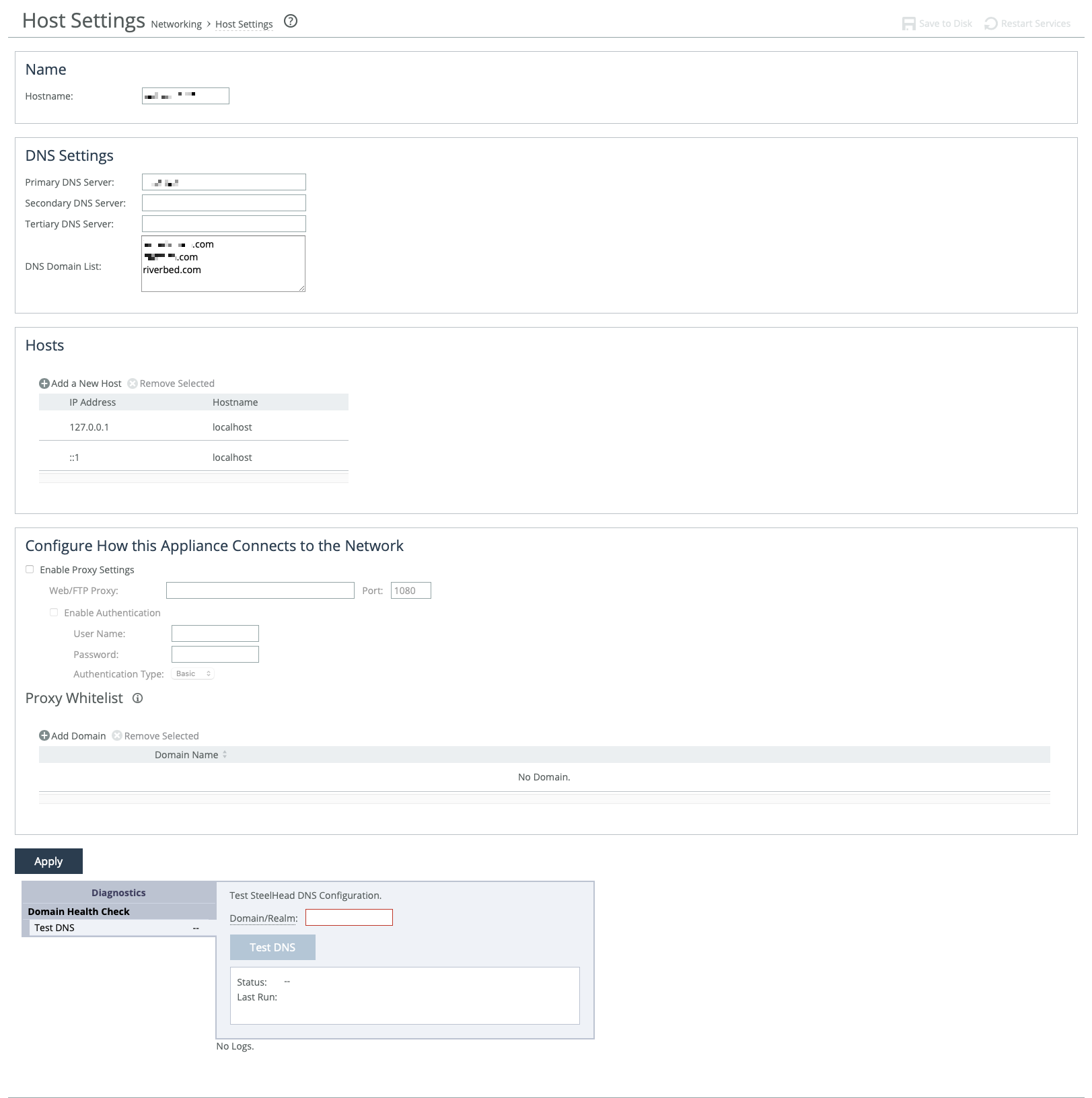
Host settings—including base (primary, auxiliary) and in-path interfaces—are usually set during the appliance’s initial setup. Only change them if necessary and if you’re sure about what you're doing.
We recommend using DNS resolution whenever possible. If your organization doesn’t use DNS, or if the appliance host doesn’t have a DNS entry, create a host-to-IP address resolution map under Hosts.
Use proxy settings to allow the appliance to access the web or FTP through a proxy. You can whitelist specific domains to prevent their traffic from being routed through the proxy.
A DNS test tool is available at the bottom of the page to quickly check your appliance's DNS setup.
DNS
You can enter the IP addresses for your primary DNS server and, optionally, secondary and tertiary servers. IPv6 addresses are allowed.
You can also set up a centralized DNS domain list—an ordered list of domain suffixes used in your organization. This allows you to use short hostnames instead of full domain names when configuring the appliance. The appliance automatically tries each domain in the list, in order, until it finds a match.
For example, if you enter exchange as your SMTP server, and your organization’s Exchange server full name is exchange.mydomain2.com, the appliance will check the domain list:
mydomain1.com → no match
mydomain2.com → match found
It then completes the name as exchange.mydomain2.com.
Proxy
IPv6 addresses supported. You can enable web or FTP proxy access under Configure How This Appliance Connects to the Network. By default, proxy access is disabled. The default proxy port is 1080.
When proxy access is enabled, the appliance can securely connect to the Riverbed licensing portal to retrieve licenses. It can also securely contact a SteelHead SaaS Manager (SSM) for registration and management. Any connection issues will be logged.
If you're using a proxy with SSM, avoid enabling SSL/TLS inspection of traffic between the appliance and the proxy.
You can also require user credentials to access the proxy. Choose an authentication method for verifying those credentials using the following methods.
Basic
Authenticates user credentials by requesting a valid username and password. This is the default setting.
NTLM
Authenticates user credentials based on an authentication challenge and response.
Digest
Provides the same functionality as basic authentication, but with improved security because the system sends the credentials across the network as a Message Digest 5 (MD5) hash.
Allow direct communication between the appliance and specific domains by adding the domains to the whitelist. Traffic between the appliance and whitelisted domains bypass the proxy.
If you are using SCC to manage your appliances, we recommend that you add the SCC’s domain to the whitelist. Otherwise, appliance backups to SCC are blocked if a proxy is enabled.
About the DNS testing tool
The diagnostic tool at the bottom of the page helps troubleshoot common issues with Windows domain authentication when encrypted MAPI or SMB signing is used. Enter the fully qualified Active Directory domain name (usually your company’s domain name), and then run the test.
DNS testing tool showing results of a successful configuration
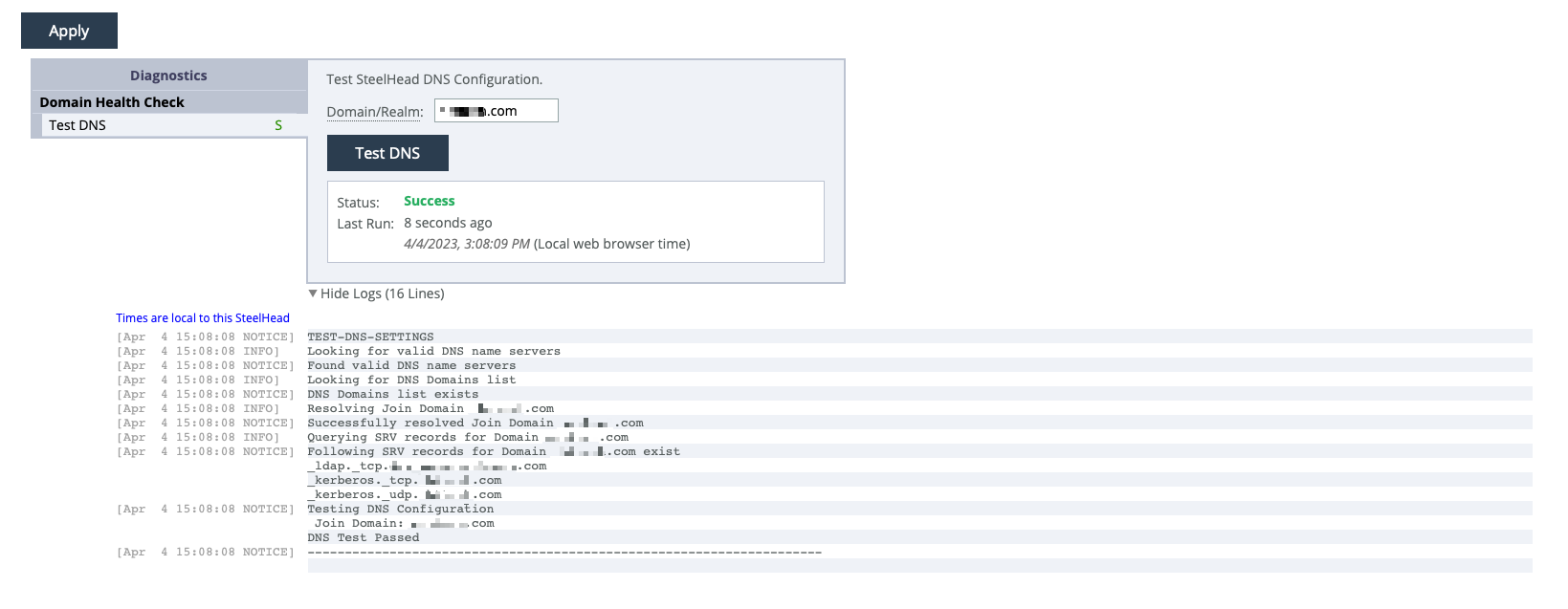
The test results section remains empty until you run the first test. After that, the most recent test results will appear. A shortened time stamp is shown on the left of each log line. Mouse over it to see the full time stamp. Some log lines may not have time stamps, as certain third-party applications generate the log data.
About base interfaces
Settings for the appliance’s primary and auxiliary interfaces are under Networking > Networking: Base Interfaces. Routing table settings are also available there. IPv4 and IPv6 are supported.
Base Interfaces page
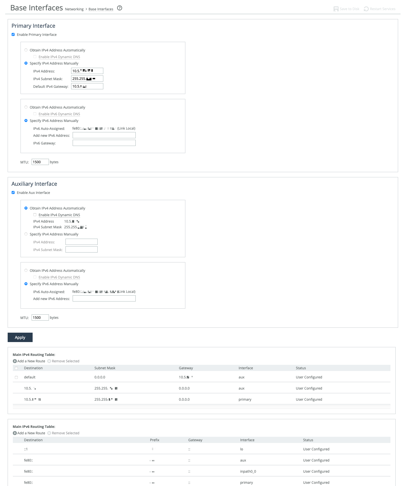
The primary interface connects to the LAN switch and serves as both the data and management interface for the appliance. You can use it to access the Management Console or CLI. It may also be used for a server-side out-of-path (OOP) deployment.
The auxiliary interface is an optional port for connecting the appliance to a non-Riverbed network management device. Its IP address must be on a different subnet than the primary interface. The auxiliary interface is only for management purposes and cannot be used for OOP deployments. Auxiliary interfaces are not applicable to cloud appliances.
Primary and in-path interfaces can share the same network subnet. Primary and auxiliary interfaces can’t.
Use the main routing table to add static routes for OOP deployments or specific management subnets.
These options are available for configuring interfaces:
Obtain IP Address Automatically
Enables the appliance to automatically get its IP addresses from a DHCP server. The appliance must be able to reach the DHCP server to request the IP addresses. You can also enable Dynamic DNS to send the appliance’s hostname with the DHCP request.
Specify IP Addresses Manually
Enables you to manually set the appliance’s IP addresses if your organization does not use DHCP. The default gateway must be in the same network as the primary interface. You must set the default gateway for in-path configurations. You do not set gateways for auxiliary interfaces.
IPv6 Auto-Assigned
Displays the link-local address that is automatically generated when IPv6 is enabled on the base interfaces.
Add New IPv6 Address
Specifies new IPv6 addresses.
MTU
Specifies the minimum transmission unit (MTU), the largest physical packet size in bytes that a network can send. The default is 1500.
Speed and duplex
These settings allow you to manually set the speed and duplex for the appliance's interface if the host device doesn't do it automatically. The speed and duplex must be the same on both the LAN and WAN interfaces. If they don’t match, you may see many errors when the appliance is in bypass mode. The default setting is "Auto."
For physical appliances, you can configure speed and duplex through the appliance’s GUI. For virtual models, these settings are managed at the virtual interface level and are not shown in the GUI.
Speed and duplex mismatches can happen easily. For example, if one end of a link is set to half or full-duplex and the other is set to auto-negotiate, the link defaults to half-duplex, causing interface errors and degraded performance.
Routers often have fixed speed and duplex settings. Make sure your router settings match the SteelHead WAN and LAN configurations, and check that your switch settings are correct.
After configuring the appliance, check for speed and duplex errors in the system logs, such as cyclic redundancy check (CRC) or frame errors. If the appliance goes into bypass mode and restarts, a mismatch might occur. To avoid this, ensure the LAN and WAN pairs have matching duplex values.
Main routing table
You can add static routes for out-of-path deployments or if your network management requires them. When adding a route, specify the destination IP address, subnet mask (for IPv4) or prefix (for IPv6), gateway address, and the interface for the route. The gateway must be in the same network as the primary or auxiliary interface you are configuring.
About in-path interfaces
In-path interfaces are used in deployments where the appliance is in the direct path (the same subnet) as the client and the server in your network, or if you want to manage the appliance through a third-party network management device.
In-path interfaces are not applicable to cloud appliances.
In-path interfaces represent host-level LAN/WAN pairs of interfaces. The number of in-path interfaces available for configuration is the same as the number of LAN/WAN pairs on the host or virtual infrastructure. In-path interface pairs are identified by slot position on physical hosts, or by label in virtual environments. For example: inpath0_0, inpath0_1, inpath1_0, inpath1_1, and so on.
You can only assign one IP address per in-path interface.
About in-path interface settings
In-path settings are under Networking > Networking: In-Path Settings.
In-path interface settings
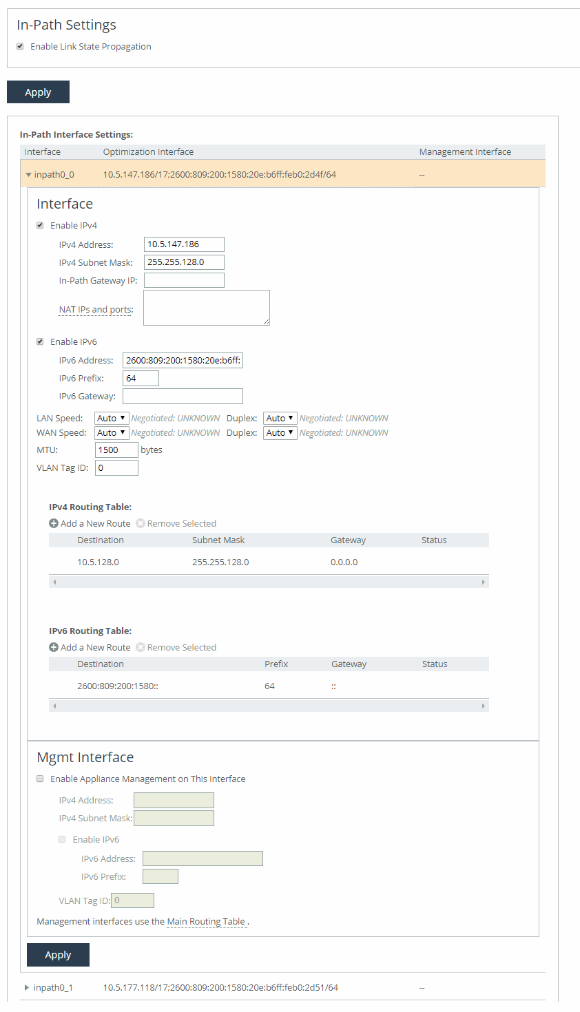
Enable Link State Propagation
Shortens the recovery time of a link failure in physical in-path deployments. Link state propagation (LSP) communicates link status among connected appliances. When enabled, the appliance monitors the link state of all connected peer appliances. When a status check fails, the appliance disconnects the corresponding interface, blocking the link. This allows a link failure to quickly propagate through a chain of appliances. If the link recovers, the appliance restores the connection on the corresponding interface.
SteelHead Cloud and SteelHead running on ESXi 4.x or Microsoft Hyper-V don’t support LSP. SteelHead running on ESXi 5.0 and later with a Riverbed NIC support LSP.
Other in-path interface settings are very similar to the base interface settings, with these differences:
• If there’s a routed network on the LAN-side of the in-path appliance, the router that is the default gateway for the appliance must not have the ACL configured to drop packets from the remote hosts as its source. The in-path appliance uses IP masquerading to appear as the remote server.
• In the case of UDP encapsulation with NAT, different SteelHeads could use the same public-facing destination addresses. To uniquely identify such SteelHeads, specify a NAT IPv4 address paired with a specific port opened on the NAT in the NAT IPs and ports field. Specify multiple NAT IPs and ports on separate lines.
• For IPv6, specify a global or site-local IPv6 address. You can’t use a DHCP server to assign an IPv6 address automatically.
• For IPv4, if you have a router (or a Layer-3 switch) on the LAN side of your network, specify this device as the in-path gateway. For IPv6, you can use a link local address.
VLAN tag ID
Specifies a numerical ID from 0 to 4094 that identifies a specific VLAN. Enter “all” to match all VLANs, or “untagged” to match untagged connections. Passed-through traffic maintains existing VLAN tags. The default is 0.
Enable Appliance Management on This Interface
Enables reachability through the physical LAN and WAN interfaces to connect a third-party management device.
In-path routing table
You can configure interface-specific static routing tables for in-path interfaces. Specify the destination IP address and the IP address for the gateway. The gateway must be in the same network as the in-path interface.
In-path interfaces for appliance management
You can also use in-path interfaces to connect the appliance to non-Riverbed network management devices. This secondary management interface (MIP) enables you to manage appliances from a private network while maintaining a logical separation of network traffic, eliminating the need to deploy a switch or borrow a switch port.
Some deployments don’t allow access to the MIP when plugged into a private subnet with a separate IP address space. In this type of deployment, you can’t use the in-path interfaces for appliance management.
MIP for third-party management device
A MIP interface is accessible from LAN and WAN sides, and you can reach it even when the primary interface is unavailable, the optimization service isn’t running, or the logical in-path interface fails. A MIP interface isn’t accessible if the physical LAN and WAN interfaces fail.
MIP interfaces use the main routing table. They support IPv6 addresses and 802.1Q VLAN. Any connections destined to a MIP aren’t optimized and don’t appear in the Current Connections report.
A MIP must be in its own subnet. It can’t reside in the same subnet as the primary or auxiliary interfaces and it can’t share the same subnet with any other interfaces on the appliance.
With LSP or fail-to-block enabled, a MIP becomes unreachable if its corresponding in-path interface fails.
You can remove MIPs from the base interfaces main routing table.
About general service settings
Network services settings are under Optimization > Network Services: General Service Settings. This feature is not applicable to cloud appliances.
The network services settings allow you to configure how the appliance’s acceleration service interacts with the network. Some of these settings are specific to your deployment. You can enable in-path, out-of-path, and failover. Other settings include limits for half-open connections and the maximum connection pool size. If your appliance has multiple bypass network interface cards (NICs), you’ll have options to enable in-path support for those ports. The number of interface options depends on how many LAN and WAN port pairs are enabled on your appliance.
In-path support
Enable In-Path Support
Enables optimization on traffic that is in the direct path of the client, server, and SteelHead.
Reset Existing Client Connections on Start Up
Enables global auto kickoff. When enabled, this feature resets existing connections, forcing them to be re-created when you restart the service. The connections are then accelerated. This is useful when making changes to the appliance that you want applied to existing connections. Auto kickoff is also available in in-path rule settings.
Enable L4/PBR/WCCP Support
Enables optional, virtual in-path support on all the interfaces for networks that use Layer-4 switches, PBR, WCCP, and Interceptor. External traffic redirection is supported only on the first in-path interface. These redirection methods are available:
• Layer-4 Switch—You enable Layer-4 switch support when you have multiple SteelHeads in your network, so that you can manage large bandwidth requirements.
• Policy-Based Routing (PBR)—PBR allows you to define policies to route packets instead of relying on routing protocols. You enable PBR to redirect traffic that you want optimized by a SteelHead that is not in the direct physical path between the client and server.
• Web Cache Communication Protocol (WCCP)—If your network design requires you to use WCCP, a packet redirection mechanism directs packets to appliances that aren’t in the direct physical path to ensure that they’re accelerated.
Enable Optimizations on Interface <interface-name>
Enables in-path support for additional bypass cards. If your appliance has multiple two-port or four-port bypass cards, the Management Console will display options to enable in-path support for these ports. The number of available interface options depends on how many LAN and WAN port pairs are enabled on your SteelHead.
The interface names for the bypass cards combine the slot number and port pair (inpath<slot><pair>, inpath<slot><pair>). For example, a four-port bypass card in slot 0 will have interface names like inpath0_0 and inpath0_1. If the bypass card is in slot 1, the names will be inpath1_0 and inpath1_1. For installation details of additional bypass cards, refer to the Riverbed Hardware Platforms Guide.
Out-of-path support
Enable Out-of-Path Support
Enables out-of-path support on a server-side SteelHead, where only a SteelHead primary interface connects to the network. The SteelHead can be placed anywhere in the LAN. In this setup, there is no redirecting device. On the client-side SteelHead, you configure fixed-target in-path rules that point to the primary IP address of the out-of-path SteelHead. This SteelHead uses its primary IP to communicate with the server. The remote SteelHead must be in physical or virtual in-path mode.
If using out-of-path with failover support, you must configure fixed-target rules for both the primary (master) and backup appliances.
Connection limits
Half-Open Connection Limit per Source IP
This feature limits half-open connections from a client (source IP address) attempting to connect to invalid hosts or ports. It helps block activities like viruses or port scanners that make multiple invalid connection attempts at once. It doesn’t affect normal connections to valid hosts.
The appliance tracks the number of half-open connections, which are attempts to check if a server connection can be established. If the number exceeds the set limit (default is 4096), new connections from that source IP are passed through without optimization.
If a client is connecting to valid hosts at a very high rate, some connections may be unoptimized, even if they are all valid.
Maximum Connection Pool Size
Specifies the maximum number of TCP connections in a connection pool. Connection pooling improves performance by reusing active connections instead of creating new ones for every request. This is especially useful for protocols like HTTP, which create many short-lived connections.
When a client requests a connection to a server it has already accessed, the connection pool manager checks for an available idle connection. If one is found, it's reused, saving time by avoiding the need for a new TCP handshake. If no connections are available and the pool size has not reached its maximum, a new connection is created and added to the pool. Once the pool reaches its limit, new requests will be queued until a connection is available or the attempt times out. The default pool size is 20. A setting of 0 disables connection pooling. To apply changes, you must restart the appliance.
You can use the Connection Pooling report to assess whether the pool size needs adjustment. If the report shows that many requests are being missed by the pool, consider increasing the pool size.
Failover support
To support failover in IPv6 environments, IPv6 connection forwarding must be enabled
Enable Failover Support
Configures a failover deployment on either a primary or backup SteelHead. If the primary appliance fails, the backup appliance takes over with a warm data store, allowing it to immediately deliver fully optimized performance. Both the primary and backup SteelHeads must be the same hardware model.
Current Appliance is
Allows you to select Master or Backup from the drop-down list. A master SteelHead is the primary appliance; the backup SteelHead automatically takes over traffic optimization if the primary fails.
IP Address (peer in-path interface)
Specifies the IP address for the peer appliance. You must specify the in-path IP address, not the primary interface IP address.
Packet mode optimization
Enable Packet Mode Optimization
Optimizes bandwidth for TCP or UDP over IPv4 or IPv6 by performing packet-by-packet single data rate (SDR) (Single Data Rate) optimization. It uses fixed-target packet mode optimization in-path rules. The feature is disabled by default and requires a service restart to activate.
About failover
In case of power loss or failure, appliances enter bypass mode to prevent network disruption. To maintain acceleration, you can set up redundant appliances as failover pairs.
For physical in-path failover, you configure two appliances: a primary and a backup. The primary is active, handling traffic, while the backup stays passive, checking the primary’s status. If the primary fails or hits its connection limit, the backup takes over. When the primary recovers, it notifies the backup, which stops handling new connections but continues processing existing ones until they finish.
In an out-of-path failover deployment, you deploy two server-side appliances and add a fixed-target rule to the client-side appliance defining primary and backup target appliances. When both the primary and backup appliances are functioning properly, the connections traverse the primary appliance. If the primary appliance fails, connections traverse the backup.
In an out-of-path failover setup, you deploy two server-side appliances and set a fixed-target rule on the client-side appliance to define the primary and backup. Normally, traffic goes through the primary appliance. If it fails, traffic shifts to the backup. The primary uses an out-of-band (OOB) connection to share internal data, and if it fails, the client-side appliance will switch to the backup after 40 to 45 seconds. During this time, new connections are passed through unoptimized. Every 30 seconds, the client-side appliance tries to reconnect to the primary. If both appliances are unreachable, new connections pass through unoptimized.
About primary and backup failover pairs
In addition to enabling failover and configuring peers, you must synchronize the data stores for the primary-backup pairs to ensure optimal use of SDR for warm data transfer. With warm transfers, only new or modified data is sent, significantly improving data transfer speeds over the WAN.
About VLAN tags
SteelHead supports the IEEE 802.1Q networking standard for Ethernet frame VLAN tagging. The standard adds a 32-bit field between the source MAC address and the EtherType fields of the original frame. VLAN tags, added to frames when they enter a VLAN-aware portion of the network to represent their VLAN membership, help keep traffic from different networks separated when traversing shared links and devices.
Several settings throughout the Management Console provide the option to specify VLAN tag IDs. A VLAN ID is a number from 1 to 4094. Unless otherwise noted in an item’s description, you can enter “all” to apply the setting to all VLANs, or “untagged” to apply it to untagged connections. A zero (0) value specifies untagged, or native VLAN, and is the correct setting if there are no VLANs present.
By default, rules apply to all VLAN values unless you specify a particular VLAN ID. Pass-through traffic maintains any preexisting VLAN tagging between the LAN and WAN interfaces.
If an appliance can’t determine which VLAN the traffic belongs, it doesn’t use the VLAN tag (assuming that there’s no router between the appliance and the client or server systems).
About auto kickoff and client connection reset
Auto kickoff forces client systems to reestablish their connections with the appliance by resetting existing connections. This occurs when the service is restarted, and after the connections are reestablished, traffic is accelerated.
While most connections are short-lived and don't require kickoff, it is useful for long-lived connections, like data replication, or in environments with challenging conditions. For example, in a remote branch office with a slow T1 link and a high round-trip time, auto kickoff helps ensure graceful acceleration without interrupting the connection.
Auto kickoff should not be enabled for in-path appliances that use autodiscover or if there is no appliance on the remote side of the network. By default, appliances autodiscover all connections.
You can enable kickoff:
• globally for all existing client connections under Optimization > Network Services: General Service Settings.
• for all existing connections that match an in-path rule with kickoff enabled.
• for a single pass-through or accelerated connection in the Current Connections report, one connection at a time.
When enabled and the service is restarted, the appliance sends RST packets to close connections and prevents further kickoffs until the service is restarted again. If no data is transferred, the connection isn't immediately reset, but it will reset when the client or server attempts to send a message. So, it may take time for idle connections to reset.
Generally, it's better not to enable global kickoff, as it disrupts all existing connections. Instead, use in-path rules to reset connections for specific subnets, IP addresses, or ports. These rules override the global setting. The appliance applies the first matching rule and resets connections based on the source and destination attributes. For example, a rule that matches connections from 192.0.2.0/24 to 192.0.3.0/24 will reset those connections when the service restarts.
About IP address formats
For settings that require IP addresses in the Management Console, use these accepted formats:
• IPv4 addresses—Use the format x.x.x.x, where x is a decimal value between 0 and 255, with each octet separated by periods. An IPv4 address must have three periods and four octets. Optionally, you can add a prefix (for example, 192.168.1.0/24), which specifies the subnet mask. The IPv4 prefix length can be between 1 and 32.
• IPv6 addresses—Use the format y:y:y:y:y:y:y:y, where y is a segment with a hexadecimal value between 0 and FFFF. The segments are separated by colons. A normal IPv6 address consists of eight segments. Short-form notation allows removing leading zeros in a segment and using double colons (::) to represent consecutive zero segments. The IPv6 prefix length is from 1 to 128.
Wildcard entries are allowed unless specified otherwise in the description of the setting.
Examples | Description |
|---|
192.0.2.0 | IPv4 |
203.0.113.0/24 | IPv4 where “/24” is the subnet mask prefix |
2001:0DB8:ABCD:0012:0000:0000:0000:12FF | IPv6 expanded |
2001:DB8:ABCD:12:0000:0000:0000:12FF | IPv6 with leading zeros removed |
2001:DB8:ABCD:12::12FF | IPv6 with leading zeros and all-zero segments removed |
2001:DB8:ABCD:12::12FF/64 | IPv6 with short notation and subnet mask prefix |
0.0.0.0/0 or All IPv4 | Wildcards for all single-stack IPv4 |
::/0 or All IPv6 | Wildcards for all single-stack IPv6 |
All IP | Wildcard for all IP addresses |