Configuring BGP, OSPF, Static Routing, and Route Retraction on SteelHead SD
This topic describes how to configuring SteelHead SD Border Gateway Protocol (BGP), open shortest path first (OSPF) with an area border router (ABR), static routing, and route retraction. It includes these sections:
Before you begin configuring BGP and OSPF for SteelHead SD, we recommend you read
Dynamic routing overview in the
SteelConnect Manager User Guide. The procedures here provide the basic steps for configuring SteelHead SD appliances.
Configuring BGP on SteelHead SD
This section describes how to configuring BGP on SteelHead SD. It includes these sections:
BGP on SteelHead SD overview
SteelHead SD provides full BGP support for local autonomous system (AS) numbers and neighbor configurations (including router ID, password, keepalive time, and hold time) for SteelHead SD 570-SD, 770-SD, and 3070-SD appliances and the SteelConnect SDI-2030 gateway located at the branch.
SteelHead SD provides support for both exterior Border Gateway Protocol (eBGP) and interior Border Gateway Protocol (iBGP). SteelHead SD doesn’t restrict BGP to the LAN or the WAN; it can communicate with its associated neighbors regardless of whether it is on the LAN or WAN.
You can configure BGP regardless of whether it is a zone or an uplink.
Before you begin configuring BGP for SteelHead SD, we recommend you consult
BGP in the
SteelConnect Manager User Guide.
Enabling BGP and configuring BGP neighbors on SteelHead SD
This section describes how to enable BGP and configure BGP neighbors on branch SteelHead SD appliances. By default, BGP is disabled.
For SteelHead SD appliances, you can only add BGP neighbors under the Appliances > BGP tab. You can’t add BGP neighbors from the Routing > BGP page.
Branch community list
SteelConnect 2.12 enables you to specify a branch community for BGP configurations. Every site has a default branch community configured automatically. You can override the default branch community by attaching a community list created based on your requirements. You can create a community under Routing > Community List. For details, see
Creating routing community lists.
The prefixes reported from a site are tagged with the branch community of its own site and with the branch community of the site where the prefix is configured. When the branch community is updated all the prefixes reported are updated with the revised branch community. When a community in the branch-community configuration is removed, the branch community is updated with the default value.
To enable BGP and configure a BGP neighbor
1. Choose Appliances and select the appliance to expand the pane.
2. Select the BGP tab.
3. Specify an AS number in Local AS to start a BGP session. The range is from 1 to 4294967295.
4. Click the search selector and select a branch community from the list. If no branch community is selected, the appliance receives a unique string.
5. Under BGP neighbors, click Add BGP Neighbor.
Creating a BGP neighbor
6. Specify a name for the BGP neighbor.
7. Specify the IP address of the BGP neighbor.
8. Specify the remote AS number that the BGP peer belongs to: for example, 200. The range is from 1 to 4294967295.
9. The remainder of the BGP attributes are provided by default. They can be changed based on your administrator settings. Optionally, fill out these BGP neighbor attributes:
–Password - Optionally, type a password to enable MD5 authentication. You must use the same password on both BGP neighbors. If you do not require MD5 authentication, you can leave this field blank.
–Click the eye icon to see the password as you type. The view persists until you click the eye icon again to hide the password.
–Keep Alive Time - Optionally, specify the amount of time, in seconds, that the eBGP neighbors exchange keepalive messages to determine whether a link has failed or is no longer available. The neighbors exchange keepalive messages often enough so that the hold time doesn’t expire. The default setting is 60.
–Hold Time - Optionally, specify the amount of time, in seconds, that a gateway neighbor waits for an incoming keepalive, update, or notification message from a neighbor before it assumes its neighbor is down. If the gateway doesn’t receive a keepalive, update, or notification message from its neighbor within the period specified, it closes the connection and routing through that neighbor becomes unavailable.
A 0 value means that no keepalive messages are sent and the connection will never close. The hold-time range is from 0 to 65535. The default setting is 180.
The hold-time value is three times the interval at which keepalive messages are sent. Using the default values for the keepalive time of 60 and the hold time of 180, the settings work together like this: after two neighbors establish an eBGP session, 60 seconds later they’ll each send a keepalive message. When a gateway receives a keepalive message from its neighbor, that gateway’s hold time for the session will have counted down from 180 to 120, but it’s then reset to 180. This process continues every 60 seconds. However, should neighbor A lose power, then neighbor B won’t receive any keepalives. So after 180 seconds, neighbor B determines that neighbor A is down and closes the session.
–Weight - Specify the BGP weight value to the routes received from the BGP neighbor. A route with a high weight value is preferred among multiple routes with the same destination. The default value is range is 2 to 65534. For details on how the weight metric is used in BGP path selection, see
Configuring BGP path selection.
–Next hop self - Click On to change the next hop attribute for received updates to its own IP address. Enable this option to change the next-hop attribute for external networks that will be advertised to branch route.
When routes from another AS are learned via the eBGP neighbor, the next hop for that route isn’t changed when it is passed to its iBGP peers. As an iBGP peer may not be aware of next hop of the external route, that route becomes unreachable for the iBGP peer. If the iBGP neighbor is configured with the Next-hop self option, the next hop is changed to its own interface address which is reachable from the iBGP neighbor.
–Default route originate - Click On to distribute the default route (0.0.0.0/0) to the specified BGP neighbor. The default setting is Off.
Route map - Click the search selector and select the route use case. The routing policies defined by the selected route map are applied while accepting routes to the BGP neighbor.
10. Click Submit.
11. Repeat
Step 5 through
Step 10 if you have two MPLS providers that need to do BGP peering with the current appliance. You need to create a BGP configuration for each one.
12. Repeat this process for other SteelHead SDs behind other routers.
BGP redistribution and summarization can only be configured after you have defined route maps and prefixes.
Configuring BGP routing policies
Optionally, you can configure BGP routing polices by defining inbound and outbound prefixes, AS paths, and route maps for BGP neighbors. By specifying these options, you can define what inbound and outbound routes are allowed or denied for BGP neighbors.
We recommend you define route maps, AS lists, and prefix lists before you configure the inbound and outbound settings. For details on configuring routing policies, see
Overview of routing policies on SteelHead SD.
Configuring BGP path selection
BGP path selection uses a defined set of criteria to determine the most efficient route through a network. The criteria is listed in the same order in which BGP uses them to select the optimal routes to be injected into the IP routing table.
1. Highest weight - You configure this value when you configure BGP neighbor (Appliances > BGP tab: Add BGP Neighbor). A route with a high weight value is preferred among multiple routes with the same destination. For details, see
Enabling BGP and configuring BGP neighbors on SteelHead SD.
2. Highest local preference - you configure this value when you create BGP routing polices (Routing > Route Maps: Add Route Map). For example, when you create a route map with the use case: Policies at the BGP neighbor level. The default value for the local preference is 100. If a route has no local preference specified it is treated as if it had a local preference of 100. If the iBGP speaker receives multiple routes to the same destination, then the route with the highest value is preferred. For details, see
Configuring route maps.
3. Locally generated - Prefer a route that is locally sourced. The best path selection algorithm uses this criteria to prefer paths that originate locally with a network statement, an aggregate statement or the redistribution of a route between local routing protocols. Aggregating network routes into one makes internet routing more efficient by saving network space. You don’t need to configure this setting because the gateway is able to deduce the information it is generating itself locally rather than learning it from a nonlocal source. This data is never passed outside of the local route selection process and is purely internal to the local router.
4. Shortest AS path - You configure this value when you create BGP routing polices (Routing > Route Maps: Add Route Map). For example, when you create a route map with the use case: Default route origination in BGP for a neighbor. For details, see
Creating routing AS path lists and
Configuring route maps.
5. Origin type - You configure this value when you create BGP routing polices (Routing > Route Maps: Add Route Map). For example, when you create a route map with the use case: Policies at the BGP neighbor level. The lowest origin type is the preferred path: IGP is lower than EGP, and EGP is lower than Incomplete. Only the routes with the lowest origin value are considered when multiple routes share the shortest AS path, then the algorithm continues by considering the multi exit discriminator (MED) settings. For details, see
Configuring route maps.
6. Lowest MED - You configure this value when you configure BGP (Appliances > BGP tab). MED is a BGP path attribute that can influence the route selection process. MED breaks the tie between the two routes when the weight, local preference, AS-Path, and origin type are same.
Enabling multi exit discriminator (MED) settings.
7. eBGP over iBGP - External BGP routes are preferred over internal BGP routes. iBGP or internal BGP runs within the same AS, whereas eBGP or external BGP operates between autonomous systems.
8. IBP metric - You configure this value when you create BGP routing polices (Routing > Route Maps: Add Route Map). For example, when you create a route map with the use case: Policies at the BGP neighbor level. If there is no external route selection path, the path with the lowest IGP value to the next hop is preferred. The IGP route is interior to the AS of origination. For details, see
Configuring route maps.
9. Route age - Routes with a longer age are preferred over “newer” routes or routes with a shorter age
10. Router ID - The path that originates from the BGP router with the lowest router ID is preferred. The router ID can be set manually and refers to the IP address with the highest router value. The router ID is the final tiebreaker in the BGP route selection process if there are multiple identical prefixes learned in the RIB. Typically, a tie break is found before the router ID but it is guaranteed to be different since two routers cannot have the same IP address within the same routing domain. SteelConnect doesn’t support VRF so everything is in the same routing domain and the system doesn’t overlap or duplicate addresses.
Configuring BGP inbound and outbound prefixes
Outbound fields are disabled if a cluster site is selected as a transit hub for SteelHead SD 570-SD, 770-SD, and 3070-SD appliances. For details on configuring transit hubs, see
Defining an organization in the
SteelConnect Manager User Guide.
To configure inbound and outbound BGP route settings
1. Choose Appliances and select the appliance to expand the pane.
2. Select the BGP tab.
Configuring inbound and outbound settings
3. Under Inbound, fill out these attributes:
–Prefix list - Specify the prefixes to be allowed or denied for route advertisements from the BGP neighbor to the appliance.
–AS list - Specify the AS paths. The route from the neighbor is permitted if the AS path matches the regular expression in the AS path list.
–Routemap - Specify route policy for the BGP neighbor. The routing policies defined by the selected route map are applied while accepting routes from the BGP neighbor.
4. Under outbound, fill out these attributes:
–Prefix list - Specify the prefixes to be allowed or denied for route advertisements to the BGP neighbor from the appliance.
–AS list - Specify the AS paths. The route to the neighbor is permitted if the AS path matches the regular expression in the AS path list.
–Routemap - Specify the route policy for the BGP neighbor. The routing policies defined by the selected route map are applied while accepting routes to the BGP neighbor.
5. Click Submit.
After the BGP neighbor is created, it appears in the BGP neighbors list. Click Edit to modify neighbor settings.
Configuring BGP route redistribution
SteelHead SD includes BGP options to globally configure:
•redistribution of OSPF routes into BGP.
•redistribution of static routes into BGP.
•redistribution of overlay routes into BGP.
•redistribution of traffic using the route map with the use case for static and connected route injection in BGP.
We recommend you define route policies, AS lists, and prefix lists before you configure BGP route redistribution. For details on configuring routing policies, see
Creating routing IPv4 prefix lists.
In SteelConnect 2.12, you can differentiate between static and overlay routes. Previously, there was no differentiation between overlay and static routes. To avoid this ambiguity, you can configure the Overlay to BGP option to distinguish overlay routes from static routes. The policies applied on redistribution of other routes are also applicable on overlay routes
To configure BGP route redistribution
1. Choose Appliances and select the appliance to expand the pane.
2. Select the BGP tab.
Configuring BGP route redistribution
3. Specify an AS number in Local AS. The range is from 1 to 4294967295.
4. Click the button to list the branch community strings and select one for this site.
The Branch Community option is per site and takes a community list as an argument. Every site will have a default branch community configured. You can override the default branch community by attaching a community list. The prefixes reported from a site are tagged with the branch community of its own site and with the branch community of the site where the prefix is specified.
5. Specify your BGP redistribution settings:
–OSPF to BGP - Click On to enable redistribution of OSPF routes into BGP. By default, redistribution is disabled.
Route Map - Click the search selector to select the route map. This option only applies to route maps with the use cases: OSPF route injection in BGP or User defined route map. This option redistributes OSPF routes in BGP using a list of IPv4 prefixes.
–Static to BGP - Click On enable redistribution of static routes into BGP. By default, redistribution is disabled.
Route Map - Click the search selector to select the route map. This option only applies to the route maps with the use cases: Static and connected route injection in BGP or User defined route map. This option redistributes static and connected routes in BGP using a list of IPv4 prefixes.
–Overlay to BGP - Click On enable redistribution of overlay routes into BGP. By default, redistribution is disabled. Configuring overlay routes takes effect immediately.
Route Map - - Click the search selector to select the route map. This option only applies to the route maps with the use cases: Static and connected route injection in BGP or User defined route map. This option redistributes static and connected routes in BGP using a list of IPv4 prefixes.
–Sites - Click the search selector to select the site. Overlay routes can also be redistributed based on the sites they are reported from. If no site is chosen, the prefixes from all the sites are redistributed. Sites can be added or removed. Any update to the route-map or the sites takes effect in about 60 seconds.
–Connected to BGP - Click On or Off to enable redistribution of connected routes into BGP. By default, redistribution is disabled.
Route Map - - Click the search selector to select the route map. This option only applies to the route maps with the use cases: Static and connected route injection in BGP or User defined route map. This option redistributes static and connected routes in BGP using a list of IPv4 prefixes.
6. Click Submit.
For details on configuring route maps, see
Configuring route maps.
Configuring conditional default-route originate routing
Typically, when the default-route originate attribute is configured, the default route is sent to the BGP neighbor without any conditions. To support a conditional default-originate route, a route-map is attached to the default route origination configuration and it is sent to the specified neighbor only when the route map matches at least one prefix in the IP routing table.
You configure the conditional default-route originate attribute when you create a BGP route-map with the use case: Default route origination in BGP for a neighbor.
For details on configuring route maps, see
Configuring route maps.
To configure conditional default-route originate
2. Create a route map with the use case: Default route origination in BGP for a neighbor. For details, see
Configuring route maps.
3. In the Route Maps list, select the route map you created.
4. Select the Match Criteria tab.
5. Under IP list, select created prefix list.
6. To define the match and set criteria, select the route map to expand the page.
7. Fill out the fields for the match and set criteria. The criteria differ according to the use case you have chosen. For details, see
Configuring route maps.
8. Choose Appliances and select the appliance to expand the pane.
9. Select the BGP tab.
10. Specify an AS number in Local AS to start a BGP session. The range is from 1 to 4294967295.
11. Click the search selector and select a branch community from the list. If no branch community is selected, the appliance receives a unique string.
12. Under BGP neighbors, click Add BGP Neighbor.
14. Under Default route originate, click On to distribute the default route (0.0.0.0/0) to the specified BGP neighbor. The default setting is Off.
15. Under route map, click the search selector and select the route map you created for the use case: Default route origination in BGP for a neighbor and click Submit.
Configuring the BGP origin-type attribute
When you configure BGP on SteelHead SD appliances, it receives multiple paths to the same destination.
The origin-type path attribute in a BGP update message that indicates the origin of the path. The origin-type attribute enables you to select the best path for the BGP route.
SteelHead SD supports these origin-types:
•IGP - The route is interior to the AS of origination. The routes received from BGP in this session are marked as IGP.
•EBP - Network layer reachability information (NLRI) is learned via EGP, as indicated by “e” in the BGP table.
•Incomplete - The routes that are redistributed into BGP from other protocols. The prefix originates from an aggregate statement or via redistribution of a static route.
The lowest origin type is the preferred path: IGP is lower than EGP, and EGP is lower than Incomplete. Only the routes with the lowest origin value are considered when multiple routes share the shortest AS path, then the algorithm continues by considering the multi exit discriminator (MED) settings. For details, see
Enabling multi exit discriminator (MED) settings and
Configuring BGP path selection.
You set the origin type when you create a route-map that has the use case: Policies at the BGP neighbor level use case. Enabling the origin-type attribute in a BGP route map enables you to filter the routes or change the origin type of routes received from a BGP neighbor. For details, see
Configuring BGP path selection.
You can also set the origin-type attribute in use case: User defined route map. This use case enables you to define a route map using any of the match and set criteria that are available in all the route-map use cases. For details on route maps and use cases, see
Configuring route maps.
To create a route map with the origin-type attribute
1. Choose Routing > Route Map.
2. Click Add Route Map.
3. Specify a name for the route map. Make sure you use a descriptive name to help you differentiate this route map.
4. Select the use case: Default route origination in BGP for a neighbor.
5. Click Submit.
6. Select the new policy to expand the page.
Configuring the origin-type attribute
7. Select the origin type from the list:
•igp - Set the prefix to originate from routing information learned from the interior gateway protocol (IGP) such as OSPF.
•egp -Network layer reachability information (NLRI) is learned via EGP, as indicated by “e” in the BGP table.
•incomplete - Set the prefix to originate from an aggregate statement or via redistribution of a static route.
9. Click Submit.
Enabling multi exit discriminator (MED) settings
In BGP path selection, you configure MED attributes when there are multiple paths to a destination prefix that have the same local preference and the same AS path length. The purpose of the MED settings is to select the best path when there are multiple connections between two autonomous systems.
The MED attribute is applied to outbound routes, dictating the best inbound path into the AS (assuming multiple paths exist). When a BGP speaker learns a route from a peer, it can pass the route's MED to any iBGP peers, but not to eBGP peers. As a result, the MED has relevance only between neighboring autonomous systems.
MED is a BGP path attribute that can influence the route selection process. MED breaks the tie between the two routes when the weight, local preference, AS-Path, and origin type are same. For details, see
Configuring BGP path selection.
You can configure these MED types:
•Deterministic MED - Enabling this option ensures the comparison of the MED variable when choosing routes advertised by different peers in the same autonomous system.
•Always-compare MED - Enabling this option ensures the comparison of the MED for paths from neighbors in different autonomous systems.
To enable multi-exit discriminator settings
1. Choose Appliances and select the appliance to expand the pane.
2. Select the BGP tab.
Configuring MED settings
3. Under Multi exit discriminator, enable one of these MED settings:
–Deterministic MED - Click On to ensure the comparison of the MED variable when choosing routes advertised by different peers in the same AS. The default value is Off.
–Always_compare MED - Click On to ensure the comparison of the MED for paths from neighbors in different autonomous systems. This setting useful when multiple service providers or enterprises agree on a uniform policy for setting MED. The default value is Off.
4. Click Submit.
Configuring BGP route summarization
With route summarization, a new network prefix with a shorter prefix length is advertised into BGP. Summarizing prefixes conserves router resources and accelerates best path calculation by reducing the size of the BGP table. Summarization also provides increased stability by reducing routing loops.
You can configure BGP route summarization using one of these modes:
•Manual - Creates a static route and advertises the network via a network statement. The summary route will always be advertised even if the networks are not available.
•Automatic - Creates a network range. When viable routes that match the network range enter the BGP table, an aggregate route is created. On the originating router, the aggregated prefix sets the next hop to Null 0. The route to Null 0 is automatically created by BGP to prevent routing loops.
When configured, the routing policy advertises a summary address only and not the individual prefixes to a BGP neighbor.
Routing policies only impact the underlay routing. They do not impact the overlay routing orchestrated by SCM.
To configure BGP route summarization
1. Choose Appliances and select the appliance to expand the pane.
2. Select the BGP tab.
3. Under Summarization, click Add Prefix.
You can configure one or more summary addresses matching the individual addresses to advertise to a BGP neighbor. You can also advertise individual addresses. By default, only summary addresses are advertised.
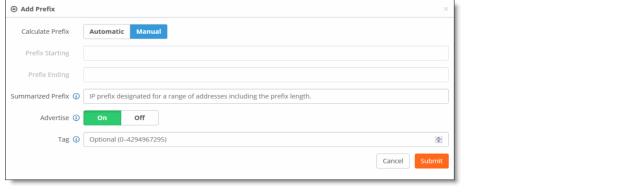
Adding AS summarization prefixes
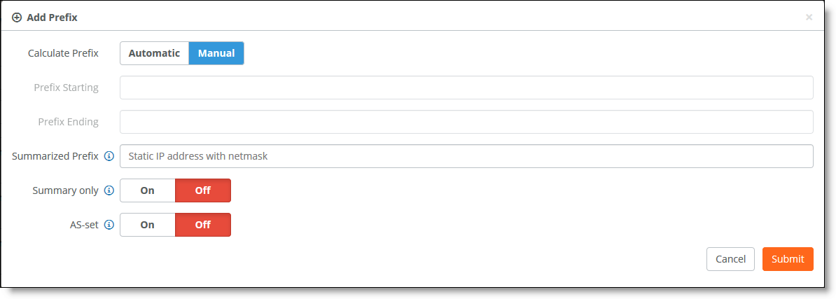
The system default is to calculate the prefix manually.
4. Click Automatic to have the system calculate the prefixes automatically, or click Manual to specify the prefix.
–For automatic prefix calculation, specify a starting and an ending address, and SteelConnect provides the summarized prefix. For example, entering the starting address 160.0.1.0 and the ending address 160.0.2.0 results in the automatic prefix 160.0.0.0/22.
–For manual prefix calculation, after Summarized Prefix, enter a static IP address with a netmask.
5. Specify the prefix starting and ending point.
6. Specify an IP address for the range of addresses including the prefix length in the Summarized Prefix text box.
7. Specify your summary and AS-set settings:
•Summary Only - Click On to advertise both summary and individual prefix advertisements to an eBGP peer.
•AS-set - Click On to provide an AS-set to use to detect and avoid routing loops. An AS-set summarizes the path attributes of all the BGP individual routes that the aggregate summarizes to help detect and avoid BGP routing loops.
8. Click Submit.
Resetting BGP sessions
If a BGP routing policy changes due to a configuration change, the BGP neighbors must be reset. Configurable routing policies for a neighbor may impact inbound or outbound routing table updates. Whenever there is a change in the routing policy, the BGP session must be cleared or reset for the new policy to take effect.
Resetting BGP sessions can be done at two levels
•at the neighbor level
•at global level
To configure BGP neighbor reset
1. Choose Appliances and select the appliance to expand the pane.
2. Select the BGP tab.
Resetting BGP
sessions
3. Under BGP neighbor reset, specify these settings to reset BGP neighbors:
•Reset Type - Select one of these options:
–Soft reset - A soft refreshes the route updates without tearing down existing peering sessions. A soft reset uses stored update information, at the cost of additional memory for storing the updates, to allow you to apply new BGP policy without disrupting the network. A soft reset is recommended for reconfiguring the routing table.
–Hard reset - A hard reset tears down the connection between peers including the TCP connection and deletes routes coming from the specified peer. Session will reestablish from the start once hard reset is done. The prefixes in the BGP, IP, and Forwarding Information Base (FIB) tables provided by the neighbor are lost. A hard reset is not recommended. Clearing a BGP session using a hard reset invalidates the cache and results in a negative impact on the network performance when the information in the cache becomes unavailable. A hard reset is also disruptive because active BGP sessions are torn down.
–Soft inbound reset - A soft inbound reset is the same as soft reset but refreshes only the inbound route table updates.
–Soft outbound reset - A soft outbound reset is the same as soft reset but refreshes only the outbound route table updates.
4. Under Reset options, select:
–Selected BGP neighbor to reset the BGP session at the neighbor level.
–All BGP neighbors to reset the BGP session at a global level. Be advised that when you specify this option, the BGP tab disappears as it is applicable to all BGP neighbors.
5. Click the search selector to select the BGP neighbor for which you want to reset the session.
6. Click Submit.
Viewing BGP status
SCM displays the advertised and learned network routes and peering session state information. To filter the list, type a search filter in the search box; for example, type IPv6 to narrow the search to all IPv6 networks.
To view BGP neighbors
1. Choose Appliances and select the appliance you want to view.
2. Click the BGP tab to view the BGP neighbors state, received prefixes, remote AS, keep-alive value, hold time, and last error. You can edit BGP values as well.
To view BGP routing tables
1. Choose Health Check > Routing Tables.
2. Select the BGP tab and select the appliance to display the BGP learned and advertised routes.
Configuring OSPF with ABR on SteelHead SD
This section describes how to configure OSPF with ABR on SteelHead SD. It includes these sections:
Introducing OSPF with ABR
SteelHead SD provides single and multiple area OSPF with ABR and route redistribution between OSPF zone interfaces and ABRs on the LAN side of the network. You can configure OSPF regardless of whether it is a zone or an uplink.
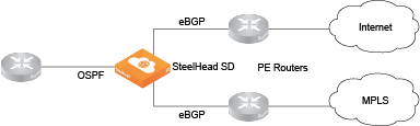
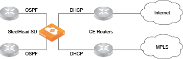
SteelHead SD supports OSPF for a branch site with one or two MPLS providers, where each provider is connected to a customer edge (CE) router. A SteelConnect branch gateway is deployed in front of the CE routers. The provider edge (PE) routers on the MPLS WAN side are using BGP and the CE routers on the LAN side are using OSPF.
OSPF single area
OSPF multiple area
Before you begin configuring OSPF for SteelHead SD, we recommend you consult
OSPF in the
SteelConnect Manager User Guide.
Creating an OSPF network
You create OSPF networks at the site level. Before configuring OSPF, make sure the appliance is registered in SCM and that OSPF is enabled on any routing device that will peer with the appliance. You create an OSPF network based on a site location that includes one area and then you attach one or more interfaces to the OSPF area.
To create an OSPF network
1. Deploy the SteelHead SD and assign a zone and uplink to a port.
2. Choose Routing > OSPF.
3. Click Add OSPF Network.
4. Select the site for the new OSPF network.
After you select a site for an OSPF network, the system automatically populates all the remaining fields based on the default settings. You can simply click Submit to create a network using the default settings. You do not have to explicitly configure the settings.
Creating an OSPF network on the branch SteelHead SD
5. Manually fill out the network attributes that you do not want to inherit:
•Site - Select the site where the OSPF network is located. Optionally, leave the site selection blank to select the first site in the list shown on the Network Designs > Sites page. Use this method to save time by quickly creating OSPF networks based on the order in which the sites appear in the site list. Creating another network and leaving the site selection blank again selects the second site in the list, and so on.
•Name - Specify a network name.
•Default Area Name - Specify a name for the area.
•Default Area ID - Specify the area in which the zone resides. This ID will typically be one of the already existing areas in the branch. If not, either specify a 32-bit unsigned number from 0 to 4294967295 or an IPv4 address in dotted decimal notation (x.x.x.x). The default setting is the backbone area ID 0; however, you can change the value to your existing area ID. For small LANs, area 0 might be all you need, but as a network grows, you will need more than one area connecting to area 0.
For a routing device to become an OSPF neighbor with another device, both devices must belong to the same area ID and their passwords and authentication methods must match.
•Inherit Org Defaults - Click On to allow the OSPF network and area to automatically inherit the settings when an organization’s default network settings are updated. This OSPF network’s settings will change to match the new values.
Click Off to define unique settings for the network and to lock the network configuration so any changes do not overwrite the settings.
•Password - Specify a password. The authentication methods appear when typing a password. All OSPFv2 exchanges between routing devices can be authenticated using one of these methods:
–MD5 - Select this tab to use the Message Digest 5 algorithm as the authentication method. MD5 authentication enables routing devices to securely identify one another before they establish adjacency. MD5 is a cryptographic hash function with a 128-bit hash value derived from the contents of the OSPF packet and a key and key ID. This method doesn’t send the password but instead calculates and includes an encoded MD5 checksum in the transmitted packet. The receiving routing device uses the key and key ID to verify the packet.
The MD5 key doesn’t have to be the same within the area, but it must be exactly the same between two OSPF neighbors.
Click the eye icon to see the password as you type. The view persists until you click the eye icon again to hide the password.
–Simple - Select this tab to include an unencrypted plain text password with the packet. The receiving routing device uses the password to verify the packet. The simple password can be from one to eight characters and can include ASCII strings. If you include spaces, enclose the password in quotation marks. Use this authentication method when devices within an area do not support the more secure MD5 authentication, as Simple is the least secure setting.
•MD5 Key ID - (Appears when you select MD5.) Specify a value to associate with the MD5 key. The ID is used by the receiver of the OSPF packet to determine which key to use for authentication.
To change your MD5 key, specify a new key and key ID. When both OSPF neighbors have a new key and key ID, the old key is deleted and the current MD5 key and key ID become active.
•Hello Interval - Specify how often, in seconds, to send a hello packet. Initially the gateway sends a hello packet to all OSPF-enabled interfaces to form an adjacency as a neighbor. The routing devices become neighbors and exchange link-state advertisements. After the gateway learns the common network topology, it sends the hello to check if an OSPF neighbor is alive. The range is from 1 to 65535. The default is 10. The hello interval must be exactly the same between two OSPF neighbors.
•Dead Interval - Specify how many seconds to wait for a hello packet before declaring an OSPF neighbor out of service, triggering a refresh of the link-state database and routing information. The range is from 1 to 65535. The default is 40. The dead interval must be exactly the same between two OSPF neighbors.
•Priority - Specify the priority for becoming the network’s designated routing device. The designated router originates network link advertisements on behalf of the network, and it establishes adjacencies with all routing devices on the network.
The routing device that has the highest priority value on the logical IP network or subnet is elected as the designated router. A priority value of 0 means that the routing device never becomes the designated router; it doesn’t even participate in the election process. A value of 1 means that the routing device participates in the election process but has the least chance of becoming a designated router. A priority of 255 means the routing device is always the designated router.
To ensure that a routing device is elected as the designated routing device, configure the priority value to a higher value than any other interface on the Ethernet network. The range is from 0 to 255. The default value is 1.
•Cost - Specify a routing metric used in the link-state calculation. OSPF selects ideal routes by locating destination routes with the least cost. Routes with lower total path metrics are preferred to those with higher path metrics. This setting controls the cost calculation of OSPF network segments. The default formula to calculate the cost for the OSPF metric is dividing the reference bandwidth (100 Mbps by default) by the interface bandwidth. For example, in the case of Ethernet, it is 100 Mbps / 10 Mbps = 10.
You can manipulate the cost by specifying a number within the range of 1 to 65535. 10 is the default setting.
The OSPF network needs a zone and, optionally, one or more uplinks to report OSPF learned routes to SCM.
If you modify the Default Area settings, keep in mind the impact the changes will have on new and existing OSPF networks. Changes to the Default Area Name, Default Area ID, and Inherit Org Defaults impact only new OSPF networks. Changes to the Password, Hello Interval, Dead Interval, Priority, and Cost impact new OSPF networks as well as existing OSPF networks with Inherit Org Defaults enabled. For details on editing OSPF networks, see
OSPF in the
SteelConnect Manager User Guide.
6. Click Submit. The OSPF network appears with the available interfaces listed.
Created OSPF network
Configuring OSPF interfaces
After you define your OSPF network, you must attach interfaces on which you want to run OSPF.
To configure OSPF interfaces
1. Choose Routing and select the OSPF network for which you want to attach an interface.
2. Select the OSPF Interfaces tab.
3. Click Attach Interface.
Attaching an OSPF interface
4. Fill out these interface attributes:
•OSPF Area - Select the OSPF area associated with the interface from the drop-down list.
•Inherit Area Values - Click On to allow the interface to automatically inherit the area settings. When enabled and this interface area is updated, this interface settings will change to match the containing OSPF area.
Click
Off to define unique settings for the area. This option locks the interface configuration so any changes to the area do not overwrite the interface parameters. For details on these unique settings, see
Step 5.
5. Click Submit.
After you attach the interface to the OSPF area, the gateway configures the zone or zones to run OSPF and establishes OSPF neighbors with LAN routers in the same network segment.
Creating OSPF areas
All of the networks learned from an OSPF zone interfaces are mapped to the OSPF area that the interface is connected to. For details on dynamic routing with OSPF, we recommend you consult
Dynamic routing overviewin the
SteelConnect Manager User Guide.
A large OSPF domain is broken into separate areas to restrict the multiplication of routes and reduce the resources required by each router to maintain its link state database. Each area is connected to a central backbone, typically called area 0. OSPF uses different types of Link State Advertisements (LSAs) to communicate link state information between neighbors.
SteelHead SD supports these LSA types:
•Standard - Routers in this area accept default and autonomous system boundary router (ASBR) injected external routes. The backbone is considered a standard area.
•Stub - Routers in this area accept inter-area routes and the default route from their ABR. They do not accept ASBR injected external routes. A stub type can contain type 1, 2, and 3 LSAs.
•Totally Stub - This type of router is similar to a stub router. They accept inter-area routes and the default route from their ABR. They do not accept ASBR injected external routes. A totally stub type can only contain type 1 and 2 LSAs, and a single type 3 LSA. The type 3 LSA describes a default route, substituted for all external and inter-area routes.
To create an OSPF area
1. Choose Routing > OSPF and select the OSPF network for which you want to create an area.
2. Select the Areas tab and click New Area.
Creating OSPF areas
3. Fill out the attributes for the OSPF area:
•Name - Specify a descriptive name for the OSPF area.
•Area ID - Specify a valid area ID as either a 32-bit unsigned number from 0 to 4294967295 or an IPv4 address in dotted decimal notation (x.x.x.x). The default setting is the backbone area ID 0; however, you can change the value to your existing area ID. For small LANs, area 0 might be all you need, but as a network grows, you will need more than one area connecting to area 0.
•Type - Specify the OSPF LSA type:
–Standard - Routers in this area accept default and autonomous system boundary router (ASBR) injected external routes. The backbone is considered a standard area.
–Stub - Routers in this area accept inter-area routes and the default route from their ABR. They do not accept ASBR injected external routes. A stub type can contain type 1, 2, and 3 LSAs.
–Totally Stub - This type of router is similar to a stub router. They accept inter-area routes and the default route from their ABR. They do not accept ASBR injected external routes. A totally stub type can only contain type 1 and 2 LSAs, and a single type 3 LSA. The type 3 LSA describes a default route, substituted for all external and inter-area routes.
•Inherit OSPF Network Values - Click On to allow the OSPF network to inherit the OSPF network values previously configured, such as password, hello interval, dead interval, priority, and cost.
Click Off to define unique settings for the network and to lock the network configuration so any changes do not overwrite the settings. This OSPF network’s settings will change to match the new values.
•OSPF Zone - Select the zone from the list. These are the zones that are participating in OSPF for the area that is configured on this page. Only one zone interface per area is allowed.
•OSPF Uplinks - Select the uplinks from the list. These are the uplinks that will be participating in OSPF in the area that is configure on this page.
•Inbound prefix - Optionally, specify the inbound prefix. Any prefixes defined in this prefix list are used to filter networks sent to this area.
•Outbound prefix - Optionally, specify the outbound prefix. Any prefixes defined in this prefix list are used to filter networks advertised from this area.
•Area ranges advertised - Specify a set of advertised routes to be advertised. In order to aggregate routing information at area boundaries, area address ranges can be employed. Each address range is specified by an [address, mask] pair.
•Area ranges not advertised - Specify the set routes that will not be advertised. In order to aggregate routing information at area boundaries, area address ranges can be employed. Each address range is specified by an [address, mask] pair. In this case, Type 3 summary-LSA is suppressed and the component networks remain hidden from other areas.
•Click Submit.
Configuring redistribution settings for OSPF
The LAN/WAN routing interworking solution bridges eBGP and OSPF to redistribute underlay routing information between the protocols on a gateway.
In 2.12, you can differentiate between static and overlay routes. Previously there was no differentiation between overlay and static routes. To avoid this ambiguity, you can configure the Overlay to OSPF option to distinguish overlay routes from static routes. The policies applied on redistribution of other routes are also applicable on overlay routes
For details on how redistribution works, see
Redistributing underlay routing in the
SteelConnect Manager User Guide.
To redistribute OSPF settings
1. Choose Routing and select the OSPF network.
2. Select the Redistribute Settings tab.
Redistributing OSPF settings
3. Optionally, specify the default metric with a range of 1 to 16777214. The ABR generates a default route with a specified metric into the stub area. The default route matches any destination that is not explicitly reachable from within the area. Routing protocols use default metrics to calculate the best path to a specified destination. The routes that are redistributed carry the specific value.
4. To specify whether you want the default route (0.0.0.0/0) injected in OSPF:
•Default Route Origination - Click On to enable default route origination. Enabling this option injects a default route into the participating areas in OSPF.
•Always - Click On to advertise the default route (0.0.0.0/0) regardless of the default route entry in the routing table.
•Metric - Optionally, specify the metric with a range of 1 to 16777214. Routing protocols use metrics to calculate the best route. When a metric value in a route matches this value, the route qualifies for distribution by the router.
•Metric type - The type of external route that you want the routes to be injected as. When the type matches the value specified, then that route is qualified to be distributed:
–Type 1 (EI)- This type includes the external cost to the destination as well as the cost (metric) to reach the AS boundary router.
–Type 2 (E2) - This type uses only the external cost to the destination and ignores the cost (metric) to reach the AS boundary router.
•Tag - Optionally, enter a value 32 bit value from 0 to 4294967295 that will be attached to the routes. When a tag in route matches this value, the route qualifies for distribution by the router.
•Route map - Click the search selector and select the route map. This option applies a routing policy based on which routes will be redistributed into OSPF.
5. Under Redistribute settings, specify your OSPF redistribution settings:
•BGP to OSPF - Click On to redistribute the routes learned from BGP into the OSPF protocol.
•Static to OSPF - Click On to redistribute static routes to OSPF.
•Overlay to OSPF - Click On to redistribute overlay routes to OSPF. Optionally, the overlay routes are redistributed based on the sites from which they were reported. If no site is chosen, the prefixes from all the sites are redistributed. Sites can be added or removed.
•Connected to OSPF - Click On to redistribute connected routes into OSPF.
6. Optionally, specify these settings if any of the above OSPF redistribution settings is enabled:
•Metric - Optionally, enter the cost metric that you want the route to be injected with into OSPF. The range is 0 to 4294967295. When a metric value in a route matches this value, the route qualifies for distribution by the router.
•Metric type - The type of external route that you want the routes to be injected as. When the type matches the value specified, then that route is qualified to be distributed:
–Type 1 (EI)- This type includes the external cost to the destination as well as the cost (metric) to reach the AS boundary router.
–Type 2 (E2) - This type uses only the external cost to the destination and ignores the cost (metric) to reach the AS boundary router.
•Tag - Optionally, enter a value 32 bit value from 0 to 4294967295 that will be attached to the routes. When a tag in route matches this value, the route qualifies for distribution by the router.
•Route map - Click the search selector and select the route map. This option applies a routing policy based on which routes will be redistributed into OSPF.
•Sites - For Overlay to OSPF routes only. Optionally, specify the site to which this redistribution policy applies. The overlay routes are redistributed based on the sites from which they were reported. Only the prefixes from configured sites will be redistributed. When no site is configured, prefixes reported from all the sites will be redistributed into the intended protocol.
7. Click Submit.
Configuring OSPF route summarization
For an OSPF area, you can filter intra-area prefixes. All routes that match the specified area range are filtered.
To add summarization for OSPF
1. Choose Routing > OSPF.
2. Select the OSPF network.
3. Select the OSPF Summarization tab.
4. Click Add Prefix to add prefixes.
You can configure one or more summary addresses matching the individual addresses to advertise to a OSPF peer. You can also advertise individual addresses. By default, only summary addresses are advertised.
Summarizing routes for OSPF
5. Click Automatic to have SCM calculate the prefixes automatically, or click Manual to specify the summarized prefix.
For automatic prefix calculation, specify a starting and an ending IP address. The system provides the summarized prefix. For example, entering the starting address 160.0.1.0 and the ending address 160.0.2.0 results in the automatic prefix 160.0.0.0/22.
6. Fill out the these attributes for automatic or manual:
•Summarized Prefix - Specify the IP prefix designated for the range of addresses, including the prefix length.
•Advertise - Click On to advertise the summary prefix. Click Off to stop advertisements of the summary address.
•Tag - Specify a 32-bit value attached to the summary route. The specified value will be tagged to the advertised summary routes.
7. Click Submit.
Viewing OSPF status
There are multiple places where SCM provides visibility to OSPF and the state of routes.
To view OSPF routing tables
1. Choose Health Check > Routing Tables.
2. Select the OSPF tab and select the appliance to display the OSPF neighbors and learned routes.
To view the Forward Information Base (FIB) routing table
1. Choose Health Check > Routing Tables.
2. Select the FIB tab and select the appliance to display the FIB information, including destination, next hop, metric value, route type, and subroute type. This table is very useful and should be the first step in debugging if the expected routes are learned by the appliance.
Defining static routes on SteelHead SD appliances
SteelHead SD provides static routing at the appliance level where it essentially acts as a router. The static route is not tied to a particular zone. Static routes:
•support IPv4 destination networks.
•support the distance metric setting that prioritizes the routing protocol when two routes have the same route destination.
To define static routes
1. Choose Routing > Static Routes.
2. Click Add Static Route.
Adding a static route
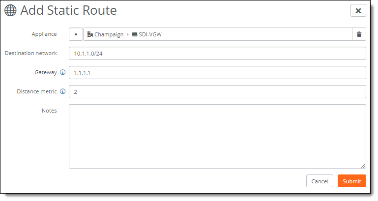
3. Select the appliance to which you want to add the static route.
4. Specify the IPv4 destination mask address.
5. Specify the IPv4 address for the gateway.
6. Specify the distance metric to prioritize the routing protocol where two routes provide the same route destination. The preferred route has the least distance metric. The default value is 2, giving the static route precedence over routes discovered by dynamic routing protocols but not over directly connected routes. The range is from 2 to 253.
This table shows the default values per route source.
Route source | Default distance |
Connected interface | 0 |
Static route | 1 |
EIGRP summary route | 5 |
BGP external (eBGP) | 20 |
EIGRP internal | 90 |
OSPF | 110 |
IS-IS | 115 |
RIP | 120 |
EIGRP external | 170 |
BGP internal (iBGP) | 200 |
Unknown | 255 |
7. Optionally, include any notes that will help identify this static route.
8. Click Submit.
SCM sends the static route configuration to the gateway. The static route appears in the Static Routes page and adds the event to the Event Log.
If a static route is configured on a gateway that is a partner in a high availability pair, SCM sends the static route information to the partner as well as sending the configuration to the gateway.
Route retraction for SteelHead SD
SteelHead SD advertises available routes and doesn’t advertise unavailable routes. If a route becomes unavailable, route retraction withdraws this route and ensures it is no longer advertised.
The behavior of route attraction and retraction is the same across all SteelConnect appliances.
To benefit from route retraction on a SteelHead SD, you need to meet the following requirements:
•You need to redistribute the overlay network into the internet gateway protocol on the LAN.
•For SteelHead SD appliances deployed in HA mode, you need to redistribute the overlay network and connected routes into iBGP.
In SteelConnect 2.12, you might not want to redistribute overlay networks into iBGP because both HA appliances will be aware of overlay routes, but you should still redistribute connected routes.
To redistribute the overlay into the internet gateway protocol on the LAN
1. In SCM, choose Routing > OSPF.
2. Select your OSPF network to edit the settings.
3. In the Redistribute settings tab, click On for Overlay to OSPF, and click On for Connected to OSPF.
4. Click Submit.
To redistribute the overlay and connected routes into iBGP
1. In SCM, choose Appliances > Overview.
2. Select the site.
3. Open the BGP tab and click On for Overlay to BGP and click On for Connected to BGP.
4. Click Submit.