Data Center Gateway Clusters
This topic describes topologies that accommodate data center workloads. It includes these sections:
Adding gateways to the data center
The SDI-2030 and 5030 gateways are the data center side of SteelConnect. These gateway models are meant for campuses and large data centers.
The SDI-2030 gateway can be deployed in-line mode as a 1 Gbps data center gateway and can serve large throughput requirements. The SDI-2030 does not support WAN optimization capabilities.
In contrast to the gateways that handle the in-path traffic, SDI-5030 data center gateways are deployed out of path deep inside the data center network. You can deploy SDI-5030 gateways in a data center with minimal redesign and disruption to the ongoing data center operations.
Because the SDI-5030 gateways are placed physically out of path from the data flow, you can deploy them with no network downtime. The system relies on either BGP traffic attraction or traffic redirection to receive SD-WAN services. Most SDI-5030 gateways use BGP to attract traffic from existing data center routers. You can also deploy a SteelHead Interceptor 9600 to provide traffic redirection. Either method is supported. See
Attracting branch traffic toward data center gateways for more information.
The SteelHead Interceptor can be used for both WAN optimization and SD-WAN when the SteelHeads are on the LAN side and the data center gateways are on the WAN side of the network. For details, see the SteelHead Interceptor User Guide.
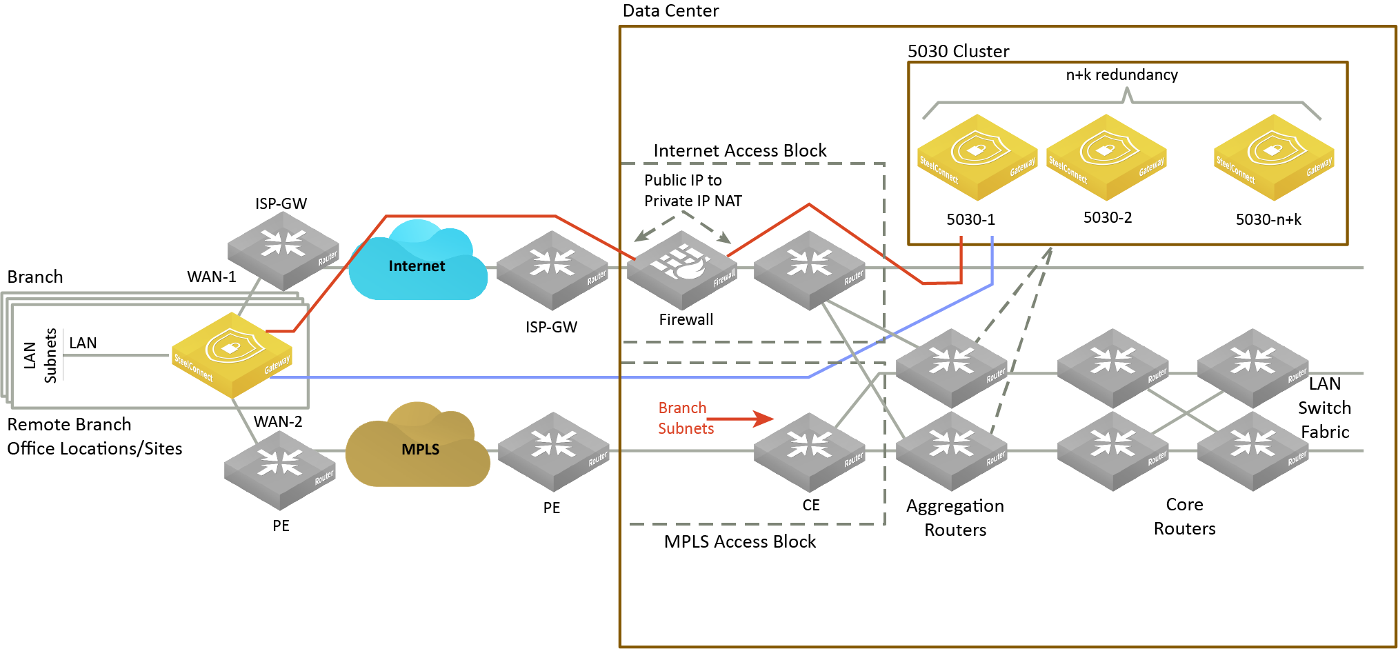
Topologies
A data center gateway scales to a higher capacity consistent with the data center environment. To accommodate data center workloads, SDI-5030 gateways are designed to operate in a cluster. Clusters provide resiliency and reliability in addition to higher bandwidth throughput.
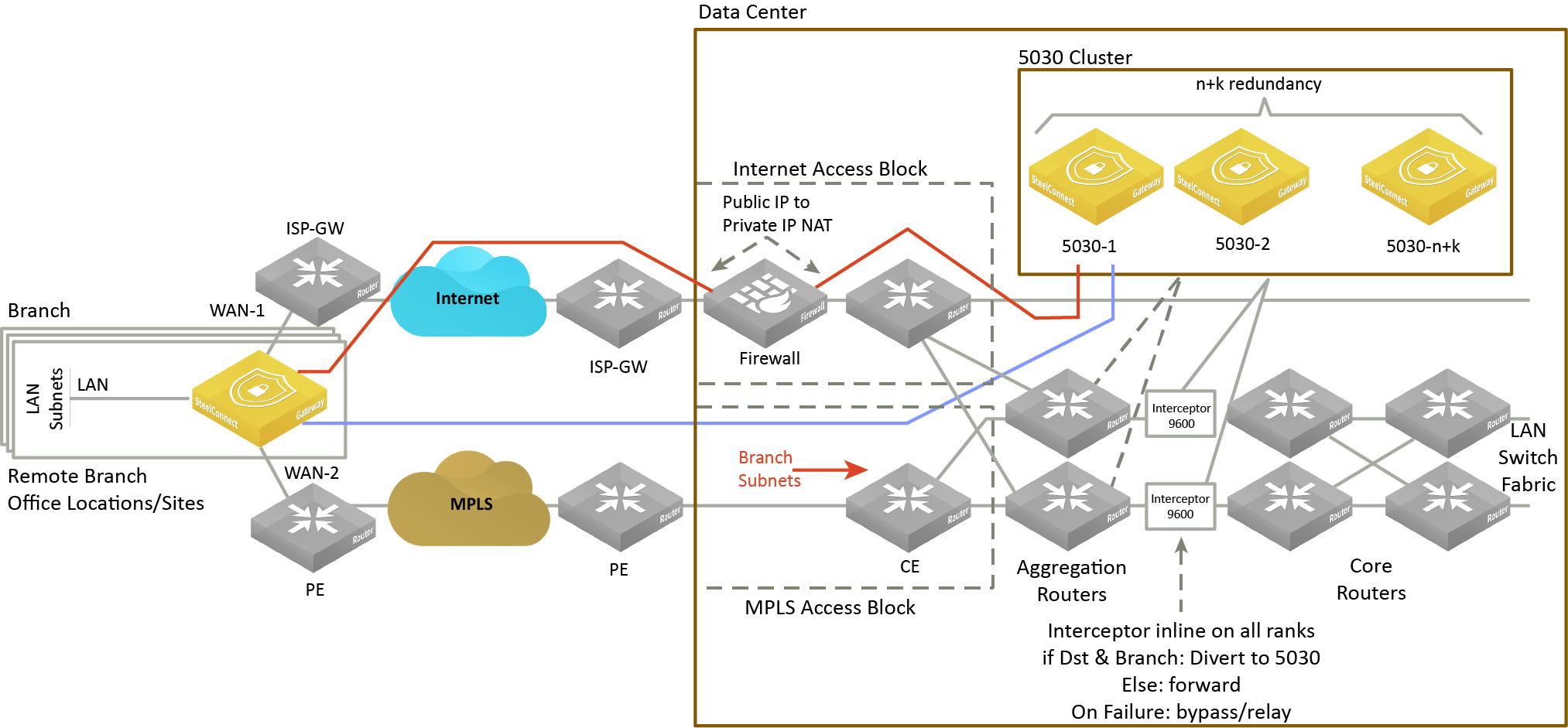
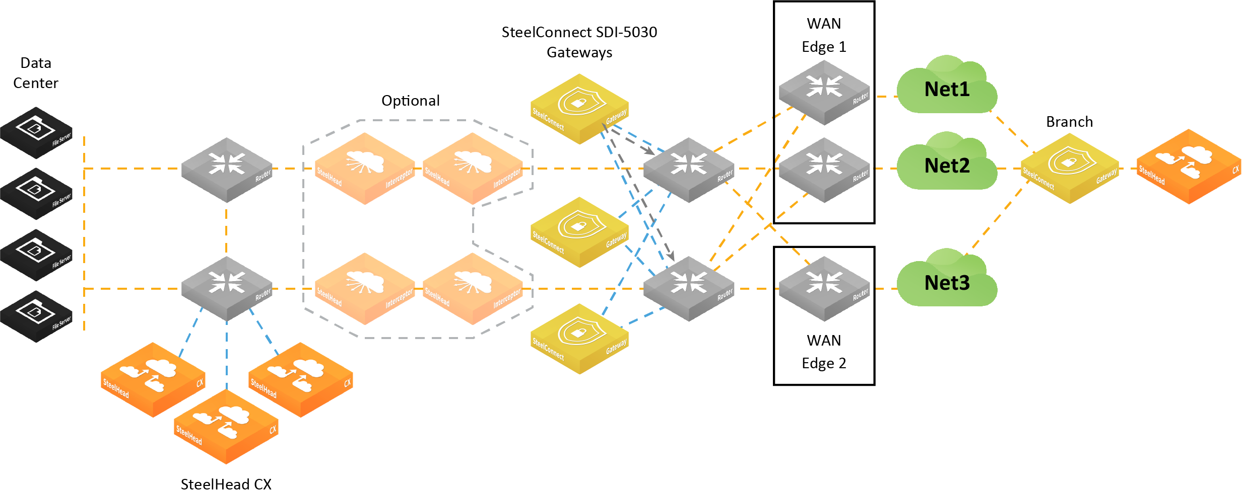
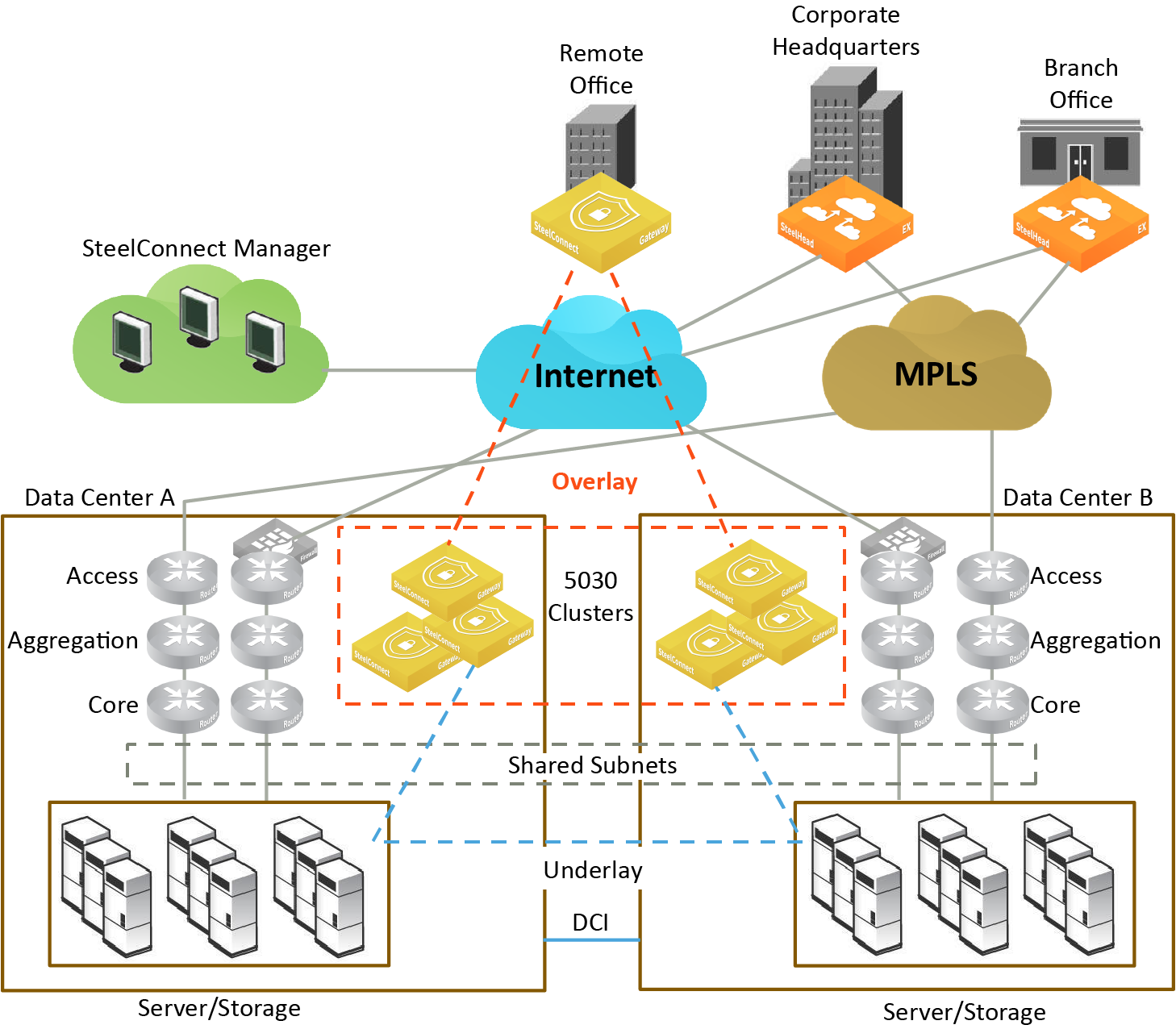
Data center cluster with SteelHead Interceptors
The software-defined WAN (SD-WAN) functionality shown in
Data center gateway cluster topology with SteelHead Interceptors is comprised of two SteelHead Interceptors and a SteelConnect data center gateways. The SteelHead Interceptors provide scalable data referencing (SDR-)aware load balancing and network traffic redirection.
Data center gateway cluster topology with SteelHead Interceptors
Data center cluster performing traffic redirection
The gateway cluster can perform traffic redirection without SteelHead Interceptors.
Data center gateway cluster topology without SteelHead Interceptors shows this topology. See
Attracting branch traffic toward data center gateways for more information.
Data center gateway cluster topology without SteelHead Interceptors
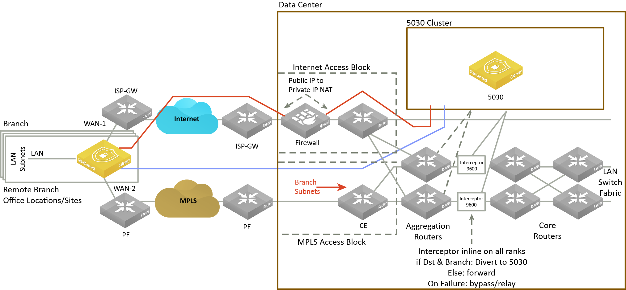
Data center cluster with a single SDI-5030 gateway
Low-end data centers can deploy a single SDI-5030 gateway to handle the data center traffic. The configuration is similar to the three SDI-5030 cluster, but is configured with just a single SDI-5030 gateway. A single SDI-5030 cluster supports both types of traffic redirection with or without SteelHead Interceptors. This configuration does not include support for high availability. The rest of the configuration remains the same as described in
Cluster components.
Data center gateway cluster topology with a single SDI-5030 gateway
Data center cluster characteristics
The SD-WAN topology requires minimal routing interaction and provides graceful failover, scalability, and easy upgrades to existing configurations.
An SDI-5030 gateway acts as a termination point for all overlay tunnels coming into a data center location from the branch offices.
An SDI-5030 gateway only serves a subset of branch traffic: overlay-to-underlay conversion ingress and underlay-to-overlay redirection on egress. In addition to serving data center-bound overlay traffic, an SDI-5030 gateway can act as a common gateway across many branches. The data center gateway achieves integration with the network underlay using External Border Gateway Protocol (eBGP) peering with WAN aggregation routers in the data center, as shown in
Data center gateway cluster topology with SteelHead Interceptors.
The SDI-5030 gateway is aware of any non-SteelHead sites connected to the network and lets those sites know of any SteelConnect-enabled branches and data centers on the WAN.
Use SCM to create and configure the gateways as out-of-path clusters on your network. SCM supports one cluster per site. Each gateway in an SDI-5030 cluster is physically connected to SCM using an out-of-band management connection.
The SDI-5030 gateway doesn’t interact with LAN switches or access points, and it doesn’t include a built-in perimeter firewall. The SDI-2030 gateway includes a build-in perimeter firewall. For details on SteelConnect as a perimeter firewall, see the SD-WAN Deployment Guide.
Cluster components
An SDI-5030 gateway cluster is simply one SDI-5030 gateway or three or more SDI-5030 gateways stacked together and wired to the data center. A minimum of three SDI-5030 gateways in a cluster is required to provide single gateway fault protection.
A cluster uses Layer 2 full-mesh interconnectivity between the individual gateways using direct interconnect for cluster spanning for multiple gateways or an external switch.
An SDI-5030 gateway cluster is made up of these components:
•Cluster nodes - The individual physical SDI-5030 gateways in the cluster.
•Data center uplinks - The network segments that connect to available WANs. Data center uplinks notify SteelConnect which WANs are available for building SDI-5030 gateway tunnels across.
•Overlay tunnel endpoints (TEPs) - The IP addresses that provide the reachability information for a branch to a data center. You can think of TEPs as the on and off ramps to the overlay network. Traffic enters and leaves the overlay through a TEP.
•Site pool - A collection of branches grouped together to communicate with a data center. Site pools provide a way to share the branch traffic load.
•Site map - A resource allocation method that tracks how a site cluster is serving the site traffic at any point in time to maintain high availability for the data center gateways. The site map tracks which site pool is associated with which data center node.
Attracting branch traffic toward data center gateways
SteelConnect can steer traffic bound for branches to the data center gateways using one of the following methods:
•Use the SteelHead Interceptor 9600 to intercept the traffic and tunnel it to the data center gateways using generic routing encapsulation (GRE). When the traffic reaches the data center, the GRE header is removed and the traffic is tunneled and redirected to the branches.
After creating the data center gateway cluster, you enable communication between the gateways in the cluster and the SteelHead Interceptor sending traffic to the cluster by entering the sd-wan and sd-wan communication CLI commands on the SteelHead Interceptor. For details on these CLI commands, see the Riverbed Command-Line Interface Reference Manual. For details on the SteelHead Interceptor, see the SteelHead Interceptor Deployment Guide.
•Use BGP traffic attraction to attract traffic bound for branches to the data center gateways and perform traffic tunneling and redirection without the SteelHead Interceptor.
An SDI-5030 gateway cluster supports BGP traffic attraction in out-of-path mode. This configuration doesn’t use Interceptor 9600 appliances to perform traffic redirection in the data center. A data center gateway cluster peers with a WAN distribution router (WDR) using BGP. The cluster then advertises Tunnel Endpoint (TEP) subnets associated with the site pool and branch subnets assigned to the site pool. The advertised TEP subnets provide an optimal route that attracts traffic from the branch to the data center, and traffic from the data center to the branch.
Specify whether to use the SteelHead Interceptor for traffic redirection, or BGP traffic attraction without the SteelHead Interceptor, when you create a gateway cluster as shown in
To create a data center gateway cluster.
Creating clusters
Before configuring a data center gateway cluster, you must add at least one SDI-5030 gateway to a site. The SDI-5030 gateways must be:
•cabled on the WAN side.
We recommend that the gateways be cabled identically for redundancy.
A cluster is limited to 256 nodes.
Configuring ports
SDI-5030 gateways use ports 1 and 2 for system-related tasks. The remaining ports are data ports.
•Port 1 is the management port dedicated to SCM. We strongly recommend using DHCP to dynamically allocate the management IP address; however, if you need to change from DHCP to static addressing, see
DNS settings. This network must provide connectivity to the internet to allow calls to SCM. DNS support is mandatory to access Riverbed services. The management port should not be accessible directly from the public internet. This port should be behind your firewall/security complex and it only requires enabling the documented outbound services.
•Port 2 is a dedicated cluster connectivity port, providing an internal, private physical connection between the SDI-5030 gateways for cluster synchronization and high availability. All SDI-5030 gateways must be Layer 2 adjacent in this network.
•Ports 3 through 10 are data ports for LAN and WAN traffic.
•Ports 5 and 6 can provide both 10G and 1G connectivity.
Whenever possible, we recommend using 10G capable ports (even for 1G connections) to guarantee best performance.
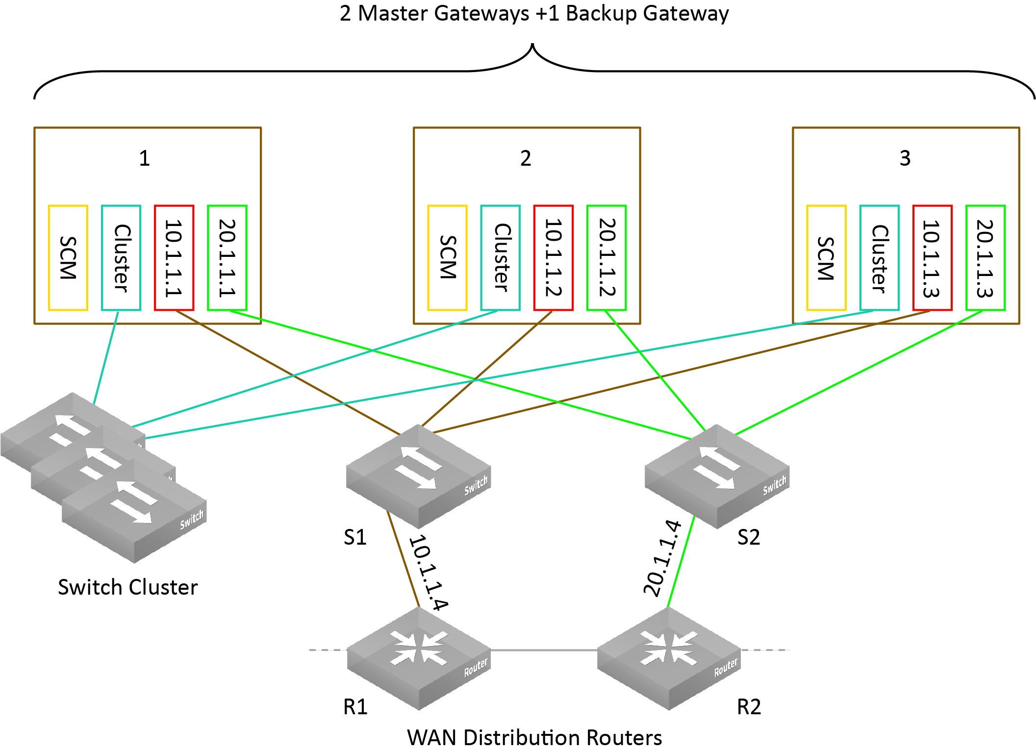
Data center gateway cluster connectivity assumes that there are two WANs available.
Data center gateway cluster connectivity
To create a data center gateway cluster
1. Choose Network Design > Clusters.
2. Click New Cluster.
3. Specify a cluster name.
4. Select the site to deploy the cluster from the drop-down list.
In a cluster workflow, it can become difficult to differentiate between data center gateways in a cluster when they are referenced on various SCM pages. We strongly recommend that you always specify a detailed location for the gateway using the Location field under the Location tab in the appliance page. Setting the location associates a gateway with its location wherever an appliance is referenced, making it easy to identify.
5. Select the cluster members from the drop-down list. For a single SDI-5030 cluster, select one member.
6. Specify the number of failover nodes. By default, the system creates one failover node in a cluster of three SDI-5030 gateways. For a single SDI-5030 cluster, leave the number of failover nodes at 0.
7. Select whether to use SteelHead Interceptors to direct traffic by choosing one of the following options:
–Click On to accept communications from an integrated SteelHead Interceptor 9600 running version 5.6.0 or later with one or more SDI-5030 gateways to help route and optimize network traffic.
–Click Off to have the gateway or gateways use BGP traffic attraction to perform routing and optimization decisions without SteelHead Interceptors.
8. For SteelHead Interceptor deployments only, specify the IP address the Interceptor will use to communicate with the cluster. The IP address has to be on the management network for the cluster.
9. Click Submit.
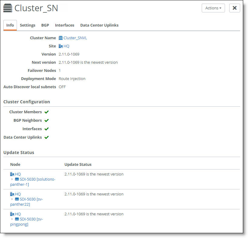
Select the cluster from the Clusters page and select the Info tab to view the cluster’s health. The cluster member status appears at the bottom of the page under cluster configuration.
Cluster configuration
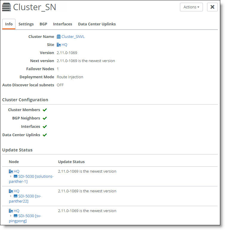
A green check mark lets you know that the item is configured correctly. A red x appears next to any item that needs attention. When a green check mark appears next to each item under Cluster Configuration, the cluster is configured correctly. Selecting the link next to the red x takes you to the configuration page where you can fix the issue.
DNS settings
We strongly recommend using DHCP to dynamically allocate the management IP address on Port 1; however, this section explains how to change from DHCP to static addressing and verify the DNS settings.
To change the management IP address from DHCP to static
1. Choose Network Design > Sites.
2. Select the site the SDI-5030 gateway is assigned to.
3. Select the DNS tab.
4. In the Site DNS servers, field, type the site-level DNS address.
5. Click Submit.
To view the DNS settings for an SDI-5030 gateway
1. Select the SDI-5030 gateway.
2. Choose Ports.
3. Select Port 1, the management port.
4. Select the Info/Mode tab.
The settings appear under Mode when Static IP is selected as the type.
Creating data center uplinks
On an SDI-5030 gateway, a data port physically connects the cluster to a WAN. Uplinks on an SDI-5030 are logical. A cluster must have at least a single uplink or multiple uplinks to the same WAN and can connect to multiple WANs.
You need to bind an uplink to a cluster and a WAN. You also need to enter an IPv4 and IPv6 address for each IP set, per uplink. The data center uplink is restricted to the IP subnet.
To create an uplink
1. Choose Network Design > Clusters.
2. Select a cluster for the uplink. Each uplink is cluster-specific and its connection type differs between clusters.
3. Select the Data Center Uplinks tab.
4. Click Add Data Center Uplink.
Data center uplink
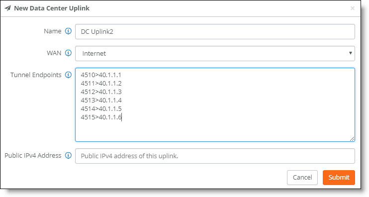
5. Type the uplink name: for example, DC Uplink2. Each uplink name must be unique.
6. Select a WAN.
SDI-5030 gateways are deployed out of path in the data center. To deploy path selection with an SDI-5030 gateway, you must enable encryption on the WAN. When encryption is disabled on a WAN, the packets are not put on any tunnel. This means that the packets from the remote branch to the SDI-5030 gateway in the data center will use the destination IP address and not the SDI-5030 gateway’s WAN interface. As a result, packets won’t be sent to the SDI-5030 gateway. With encryption enabled, packets will reach the data center because the SDI-5030 gateway will send the packets to the original destination on the LAN. For details, see
WAN settings.
7. Identify how the branch gateway will reach the correct data center gateway by specifying the tunnel endpoints for each gateway in the cluster: for example, 40.1.1.1. For a single SDI-5030 cluster, add a set of two IP addresses. For a cluster with three nodes, add a set of four IP addresses. For an SDI-5030 cluster with more than three nodes, add two IP addresses for each active node. You can also use a netmask subnet and SCM will allocate the endpoints.
You can also specify a public IP’s corresponding NAT port along with the tunnel’s endpoints.
8. Specify the public IPv4 address of the uplink with an optional netmask. This address is required for NATed internet WANs and optional for other WANs.
On MPLS you don’t need to specify the public IP address. MPLS uplinks use the private addressing you configure without translation.
9. Click Submit.
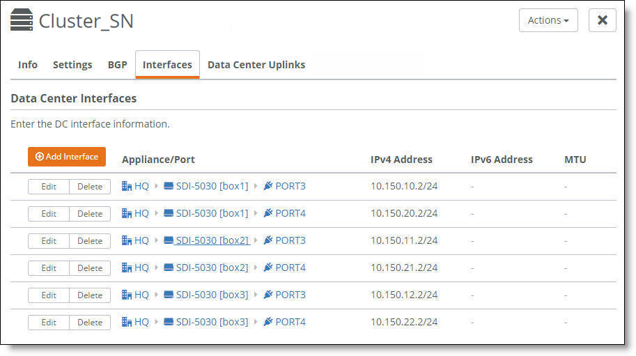
Creating interfaces
Each SDI-5030 gateway must have at least one data port (interface) connected to the WAN. If you’re creating a data center cluster of three or more SDI-5030s, these ports must be Layer 2 adjacent.
To create an interface
1. Choose Network Design > Clusters.
2. Select a cluster to associate with the interface.
3. Select the Interfaces tab.
4. Click Add Interface.
5. Select a data center port from the drop-down list. Click the search selector to search for a port.
6. Specify the IPv4 address and netmask to the SDI-5030 gateway. The netmask is required. Use this format for an individual subnet IP address and netmask: xxx.xxx.xxx.xxx/xx
7. Specify the IPv6 address for the interface. Use this format for an individual subnet IP address and netmask: x:x:x::x/xxx
8. Specify the MTU value. The MTU is the largest physical packet size, measured in bytes, that a network can send. The default value is 1500. The range is from 1280 to 9586 bytes.
9. Click Submit.
10. Repeat
Step 4 through
Step 9 to add more interfaces one at a time.
You can select the Interfaces tab to view the interfaces for a cluster.
Interfaces associated with a cluster
The next task is to configure the BGP settings to enable dynamic routing for a cluster. This task is required.
Why enable dynamic routing for a cluster?
The SDI-5030 gateways use eBGP for dynamic routing within the data center. Each SDI-5030 gateway in a cluster forms eBGP peering with the data center routers. The global BGP settings:
•establish eBGP neighbor relationships with the provider edge (PE) routers.
•enable the data center gateway to learn routes from the WAN uplinks.
Enabling dynamic routing for a data center cluster provides reachability information for the following scenarios.
For details on routing feature summary by appliance model, see
Routing feature support by model.
Forwarding packets from the branch to the data center gateway
Because the data center network needs to know how to forward tunneled packets from the branch to the correct SDI-5030 gateway, you have to define the SDI-5030 gateway tunnel endpoints in the underlay.
The SteelHead Interceptors in this figure are required if you use SteelHead Interceptors to redirect traffic to data center gateways; otherwise they are optional. See
Attracting branch traffic toward data center gateways for more information.
SteelConnect doesn’t support IPv6-based tunnel endpoints (TEPs).
Forwarding from the branch to the data center

Forwarding packets from the data center gateway to the branch
Because there can be multiple routers going to different WAN edges in the network, the SDI-5030 gateway needs to know how to forward outgoing tunneled packets heading to the branch to the correct data center router. The data center router informs the SDI-5030 gateway about the branch TEP reachability.
The SteelHead Interceptors in this figure are required if you use SteelHead Interceptors to redirect traffic to data center gateways; otherwise they are optional. See
Attracting branch traffic toward data center gateways for more information.
Forwarding from the data center to the data center router en route to the branch
Forwarding inner connections to the data center
The SDI-5030 gateway must know how to forward deencapsulated inner packets to the appropriate data center router. The data center router must tell the SDI-5030 gateways about the data center subnet reachability.
The SteelHead Interceptors in this figure are required if you use SteelHead Interceptors to redirect traffic to data center gateways; otherwise they are optional. See
Attracting branch traffic toward data center gateways for more information.
Forwarding inner connections through the data center router
Configuring BGP settings
This routing information flows between the eBGP peers:
•The SDI-5030 gateway informs the data center aggregation router of its TEP addresses that terminate on the SDI-5030 gateway.
•In the opposite direction, the WAN aggregation router advertises the TEP addresses to the branches over MPLS.
Each appliance must have at least one BGP neighbor.
BGP routing is also needed for cluster high availability. For details, see
eBGP and high availability.
For more information on dynamic routing with BGP, see
Branch dynamic routing topologies with eBGP.
First, configure the individual SDI-5030 gateways with local information.
To configure BGP peering with the WAN aggregation router
1. Choose Appliances.
2. Select an appliance.
3. Select the BGP tab.
4. Fill out these required session attributes:
•Router ID - Specify the router IPv4 or IPv6 address to uniquely identify the router in the local autonomous system (AS). The gateway can peer with any remote router that supports eBGP. eBGP must be enabled on the router.
•Local AS - Specify the AS number the router belongs to: for example, 100. The range is from 1 to 4294967295. The default value is 65000.
Next, configure the BGP information for the cluster. The cluster needs the router information to communicate with the SDI-5030 gateway.
To configure BGP for a data center cluster
1. Choose Network Design > Clusters.
2. Select a cluster by clicking the icon or name.
3. Select the BGP tab.
4. Optionally, fill out these BGP settings:
–Tunnel Endpoint Community - Restricts traffic entering a tunnel by tagging route advertisements to a BGP peer with a community attribute. This setting is optional. Specify a community name in the format AA:NN or a number between 1 and 65535.
–This attribute performs route filtering when the gateway sends a BGP advertisement toward the WAN aggregation router. It stops route advertisement into areas of the network where you don't want them.
–The same community attribute is applied to all route advertisements from the gateway. The Tunnel Endpoint (TEP) Community tag and the Branch Community tag must be different.
–You don’t need a community attribute for each unique subnet and zone advertised.
–Branch Community - Restricts traffic entering a tunnel by tagging route advertisements to a BGP peer with a community attribute. This setting is optional. Specify a community name in the format AA:NN or a number between 1 and 65535.
–This attribute filters routes when the gateway sends a BGP advertisement toward the WAN aggregation router. It stop routes advertisement into areas of the network where you don't want them.
–The same community attribute is applied to all route advertisements from the gateway. The Branch Community tag and the TEP Community tag must be different.
–You don’t need a community attribute for each unique subnet and zone advertised.
–Subnet Splitting - When set to Off, the gateway advertises the regular branch subnet prefixes (BSPs) for which it is responsible to its eBGP peers. Regular branch subnets are the actual subnets. When set to On, the gateway withdraws the BSPs and instead advertises the corresponding split subnets. Splitting the subnets makes a /24 into two /25s and therefore provides more specific routes to the destinations.
When disabled, the system withdraws the split subnets and advertises the BSP as received. You’ll likely need to assign a BGP weight or local preference to the routes being learned from the SDI-5030 gateway so that they’re more preferred than the same routes already being received by the underlay. By default, subnet splitting is off.
To add a BGP neighbor
1. Click Add BGP Neighbor.
2. Specify values for the following fields:
–In the Name field, specify a name for the neighbor.
–In the Appliance field, select an appliance from the drop-down list.
–In the IPv4 Address field, specify the neighbor’s IPv4 address.
–In the Remote AS field, specify the autonomous system number the peer belongs to: for example, 200. The range is from 1 to 4294967295. If another uplink is configured with a remote AS on the same appliance, SCM defaults to the same remote AS setting used on the previously configured uplink and you can’t change the setting.
If the default settings for the following fields are acceptable, you can simply click Submit to continue.
–In the Password field, type a password to enable MD5 authentication. You must use the same password on both BGP neighbors. If you don’t require MD5 authentication, you can leave this field blank.
–In the Keep Alive Time field, specify the amount of time, in seconds, that the eBGP neighbors exchange keepalive messages to determine whether a link has failed or is no longer available. The neighbors exchange keepalive messages often enough so that the hold time does not expire. The default setting is 60 seconds.
–In the Hold Time field, specify the amount of time, in seconds, that a gateway neighbor waits for an incoming keepalive, update, or notification message from a neighbor before it assumes its neighbor is down. If the gateway doesn’t receive a keepalive, update, or notification message from its neighbor within the period specified, it closes the connection and routing through that neighbor becomes unavailable.
A 0 value means that no keepalive messages are sent and the connection will never close. The hold-time range is from 0 to 65535. The default setting is 180 seconds (three minutes).
The hold-time value is three times the interval at which keepalive messages are sent. Using the default values for the keepalive time of 60 and the hold time of 180, the settings work together like this: after two neighbors establish an eBGP session, 60 seconds later they’ll each send a keepalive message. When a gateway receives a keepalive message from its neighbor, that gateway’s hold time for the session will have counted down from 180 to 120, but it’s then reset to 180. This process continues every 60 seconds. However, should neighbor A lose power, then neighbor B won’t receive any keepalives. So after 180 seconds, neighbor B determines that neighbor A is down and closes the session.
3. Click Submit.
4. Repeat
Step 2 to create additional neighbors one at a time.
Select the BGP tab to view the BGP neighbor configuration for a cluster.
BGP neighbors for a cluster
Fields in the BGP Neighbors table
This table lists the fields in the BGP Neighbors table.
Field | Description |
Name | The name of the neighbor. |
Appliance | The type of appliance. |
IPv4 | The neighbor’s IPv4 address. |
State | The state of the BGP neighbor. One of the following values is displayed: Established - BGP neighbor adjacency is complete. The length of time that the neighbor has been in an established state is displayed in this field. The length of time is not displayed for any of the other states. Connect - BGP is waiting for a three-way handshake to complete. Active - A successful TCP session was not started, and BGP attempts another TCP three-way handshake to establish a connection with the neighbor. Not Established - BGP neighbor adjacency has not been established. |
Received Prefixes | The number of prefixes that have been received from a BGP neighbor. |
Remote AS | The autonomous system number to which the peer belongs. |
Keep-Alive | The amount of time, in seconds, that the eBGP neighbors exchange keepalive messages to determine whether a link has failed or is no longer available. The neighbors exchange keepalive messages often enough so that the hold time does not expire. The default setting is 60. |
Hold Time | The amount of time, in seconds, that a gateway neighbor waits for an incoming keepalive, update, or notification message from a neighbor before it assumes its neighbor is down. If the gateway doesn’t receive a keepalive, update, or notification message from its neighbor within the period specified, it closes the connection and routing through that neighbor becomes unavailable. A 0 value means that no keepalive messages are sent and the connection will never close. The hold-time range is from 0 to 65535. The default setting is 180. |
Last Error | The last error code and subcode seen by this peer on this connection. The code is in a format of 0 x/0 y, where x and y are numbers that represent the main error code and the subcode for that error. See Definition of Last Error codes for a definition of these codes. |
Special consideration for iBGP and eBGP deployments
Deployments that use a combination of eBGP and iBGP require some special configuration on the routers.
SDI-5030 gateway deployment combining eBGP and iBGP
In this topology, the interior gateway protocol (IGP) in the data center underlay is iBGP, and the MPLS WAN side is using eBGP. eBGP is in use between the SDI-5030 gateways, router 1, and router 2. The SDI-5030 gateways advertise the branch prefixes and TEPs into the underlay through eBGP, with the next hop as self.
iBGP will advertise these routes but it won’t update the next hop routes advertised by the SDI-5030 gateways. Because the SDI-5030 gateway cluster requires an eBGP session with next hop routers, this requirement will have an effect on traffic if one of the WAN Distribution Routers (WDRs) through which the routes were reachable was to go down. This is a known configuration and an industry practice. This scenario requires additional CLI configuration on the routers.
For example, configure the router 1 through router 3 iBGP session or the router 2 through router 3 iBGP session like this:
On router 1
router bgp 1
neighbor <R3 interface IP address> remote-as 1
neighbor <R3 interface IP address> next-hop-self
On router 2
router bgp 1
neighbor <R3 interface IP address> remote-as 1
neighbor <R3 interface IP address> next-hop-self
Advertising the default route in IGP in the data center for internet uplinks
The packets from the remote branch to the gateway cluster in the data center on the internet uplink use the source IP address as the public IP address for the remote branch. They also use the destination IP address as the public IP address for the data center. Because the destination IP address gets NATed on the internet router or the firewall to the SDI-5030 gateway’s TEP IP, the remote branch is able to send packets to the SDI-5030 gateway cluster.
But the overlay traffic from an SDI-5030 gateway to the remote branch could fail because the source IP address will be the SDI-5030 gateway’s TEP and the destination IP address will be the public IP address of the remote branch—which is not advertised in the data center underlay.
To enable the SDI-5030 gateway to learn the default route, the network administrator or engineer for the data center must redistribute the default route into the IGP of the data center and also into the BGP session with the SDI-5030 cluster. After the SDI-5030 gateway learns the default route, it knows how to send packets out to the remote branch on the internet uplink.
Viewing cluster health
SteelConnect checks the overall cluster configuration and membership regularly to monitor a cluster’s health. When determining the overall cluster health status, SteelConnect also considers the local state of each individual appliance in a cluster.
To view cluster health
1. Choose Network Design > Clusters.
The cluster health appears.
Cluster health
A cluster’s health falls into one of these categories:
•Healthy - Indicates that all gateways in the cluster are operating normally.
•Degraded - Indicates that all gateways in the cluster aren’t operating normally. The cluster is unprotected by redundancy but is operational.
•Unhealthy - Indicates a loss of quorum resulting from one or more gateways in the cluster going offline or failing.
•Unknown - Indicates the lack of status updates because the connection to SCM is down.
2. For more details, select the cluster.
3. Select the Info tab.
The cluster member status appears. A red x appears next to any item that needs attention. Selecting the link next to the red x takes you to the configuration page where you can fix the issue. When you return to the cluster info page, a green check mark lets you know that the item is configured correctly. When a green check mark appears next to each item under Cluster Configuration, the cluster is configured correctly.
The system reports cluster health status for individual cluster members during the initial cluster configuration; it doesn’t reflect runtime status. To view cluster runtime events, view the event log. The event log reports cluster status events in 15-second intervals.
Cluster health status
Because SCM has direct visibility into the appliances, you can also investigate the status of the individual gateways within a cluster using the Appliances Overview page. You can correlate the gateway’s status with the overall cluster health because each gateway contributes to the cluster health.
To view a data center appliance status
1. Choose Appliances > Overview.
2. Find the data center gateways belonging to the cluster in the appliance list.
3. Check the appliance configuration status.
–Up to date - Indicates that appliance is running the most recent configuration.
–Pending - Indicates that the appliance hasn’t yet received the pushed configuration and the appliance is offline.
–Firmware upgrade - Indicates that a new firmware version has been downloaded to the appliance but the firmware version hasn’t been updated yet. For details on upgrading the individual appliances belonging to a cluster, see
Upgrading a data center cluster.
When one of the gateways in a cluster is offline, SCM reports an unhealthy cluster.
Deleting a cluster
Deleting a cluster deletes all data center uplinks associated with the appliances. The interfaces and BGP neighbors are not deleted and are still available as part of the individual SDI-5030 gateway configurations.
To delete a cluster
1. Choose Network Design > Clusters.
2. Select a cluster.
3. Click Actions and then select Delete this cluster from the drop-down menu.
A dialog asks for confirmation.
Deleting a cluster confirmation
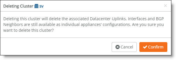
4. Click Confirm.
Viewing cluster status events
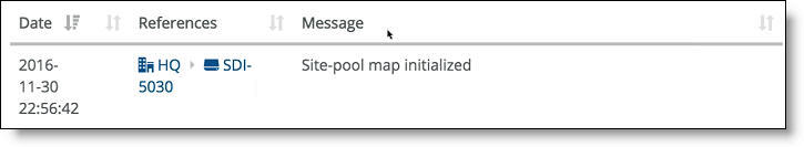
You can also check the event log to determine whether the system has initialized the site pool map for the cluster. The site pool map is initialized when the cluster configuration is complete and the cluster determines how it is going to handle the site pools using its physical resources. A site pool map initialization event indicates that the cluster has sent a site pool map to SCM and is ready to handle traffic flows.
Cluster status events are reported in 15-second intervals.
To view events
•Select the Events tab or choose Visibility > Event Log.
SCM site pool initialization event
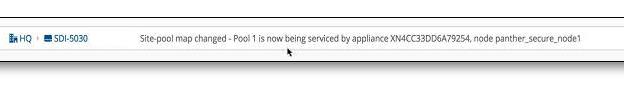
SCM also captures high-availability failover events that result in a site pool assignment change, as shown in
SCM site pool change event.
SCM site pool change event
Upgrading a data center cluster
This section describes the firmware upgrade process for a data center cluster.
Prerequisites
Before starting the upgrade, make sure each SDI-5030 node is:
•in a healthy cluster of one or more nodes. To check the cluster health, choose Network Design > Clusters and select the Info tab. The cluster health status must be “Healthy.” If the cluster health status is “Unhealthy,” see
Viewing cluster health.
•showing that there is a new firmware version available after “Next Version” on the cluster Info tab.
•using the option to apply firmware upgrades immediately. To verify, choose Organization and select the Maintenance tab. After Apply firmware upgrades immediately, check that the On button is green.
To upgrade an SDI-5030 node cluster
1. Choose Organization.
2. Select the Maintenance tab.
3. Click Upgrade Now. If the Upgrade Now button doesn’t appear, there isn’t any upgrade available.
4. Confirm that you want to upgrade the cluster.
5. Choose Clusters to view the upgrade progress and status.
–As the upgrade begins, SteelConnect removes the first node from the cluster.
–After the node is separated from the cluster, it is upgraded with the new firmware version and it reboots.
–After a successful upgrade, the appliance status indicates that the appliance is online with an up-to-date configuration.
–After the node is successfully upgraded, SteelConnect adds it back into the cluster.
If the appliance is online, but the status indicates that the upgrade has failed, select the SDI-5030 node. Click Actions, select Retry Upgrade, and click Confirm.
6. SteelConnect continues to upgrade the other SDI-5030 nodes in the cluster using the same process: removing the node from the cluster, upgrading it with the new firmware version and rebooting, and adding it back into the cluster.
When all appliances in the cluster have been upgraded successfully, the cluster reports its health status as “Healthy,” and the firmware status for each member of the cluster shows that the SDI-5030 gateway is running the newest firmware version.
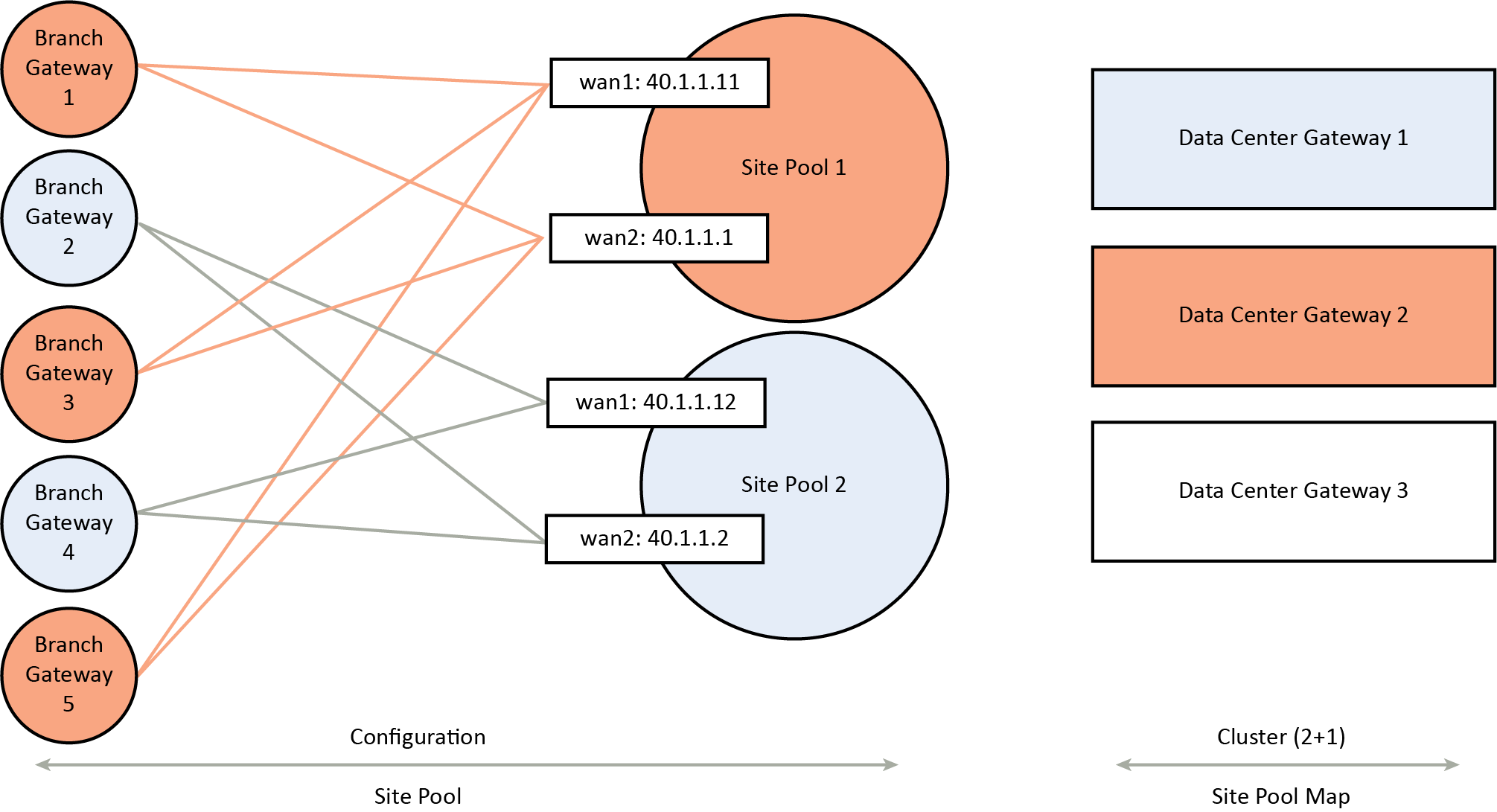
How does SteelConnect allocate resources within a cluster?
During provisioning, the system matches a site pool to a data center gateway belonging to a cluster, creating a site map.
Site pools are used for data center resiliency to ensure that in the event of a physical appliance, software, or link failure, the data center can keep track of the physical branch gateways so that their perception of IP reachability doesn’t change after a failure. Site pools allow network nodes to be dynamically provisioned while improving failover performance time and ensuring that there is never a single point of failure.
Site pools contain abstractions of physical appliances using a virtual entity. The system uses the abstractions to provide seamless high availability without having to coordinate all of the components across the entire topology. The branches are segregated into separate site pools using a round robin algorithm, so if a data center gateway fails, it impacts only a subset of the branches.
The system assigns one of the site designator instances in the lead role to be in charge of site assignment coordination across the entire cluster. The site designator splits the branch sites into two distinct site pools, such as site pool 1 and site pool 2, during provisioning. After assuming the lead role, the site designator takes an inventory of the data center gateways that can be tasked with servicing individual site pool assignments.
In
Site pool and map assignments, the site map designates data center gateway 2 with an active service assignment for site pool 1. The initial site pool assignment ensures backup service using data center gateway 1. After an appliance failure on data center gateway 2, the system reassigns site pool 2 flows to the backup data center gateway 1. No further changes to service assignment need to happen when the data center gateway 2 recovers from the failure. For details on high availability, see
How does data center high availability work?.
Site pool and map assignments
Multiple site pools are processed by a single SDI-5030 gateway. In terms of CPU resource allocation, there is a fixed amount of CPU processing allocated to each site pool.
A bin packing algorithm balances the resource consumers (traffic processing to and from the remote sites) with the resource producers (the CPU cycles required to process the traffic). Resource consumption is directly proportional to site size.
For a first approximation to place resource consumers into site pools, SteelConnect provides a uniform distribution of small, medium, and large sites into all site pools. For example, suppose you have “x” small sites, “y” medium sites, and “z” large sites allocated between four site pools (A, B, C, and D). An ideal allocation of resource consumers to site pools is to allocate one quarter of all sites (x, y, and z) to each site pool (A, B, C, and D).
The default site size is medium. You can adjust the distribution of resource consumers based on site size. The small, medium, and large site sizes are relative to ensure efficient bin packing with a fair distribution.
To adjust the distribution of resource consumers by site size
1. Choose Network Design > Sites.
2. Select a site.
3. Select the Size tab.
4. Select a site size from the drop-down list: small, medium, or large.
5. Click Submit.
Changing the site size might reassign it to another SDI-5030 in the cluster, depending on how the system redistributes the resources.
How does SteelConnect allocate site pools with multiple cluster uplinks?
Each SDI-5030 gateway can handle multiple site pools.
When a data center cluster has multiple uplinks, SCM uses tunnel endpoints (TEPs) from each uplink to create a pool. For example, suppose that there are six to ten remote sites and the cluster uplink 1 has TEPs T1 and T3. Cluster uplink 2 has TEPs T2 and T4. In this example, SteelConnect creates one pool with TEPs T1 and T2 with remote sites R1 to R5, and another pool with TEPs T3 and T4 with remote sites R6 to R10.
Definition of Last Error codes
Data in the Last Error field in the BGP Neighbors table is presented in the format 0x/0y. The following tables define the codes (0x) and subcodes (0y) of the Last Error field.
This table lists the last error codes (0x).
Last error code (0x) | Explanation |
0 | Reserved. |
1 | Message header error. |
2 | OPEN message error. |
3 | UPDATE message error. |
4 | Hold timer expired. |
5 | Finite state machine error. |
6 | BGP cease error. |
7 | BGP route refresh error. |
This table defines the subcodes for Message header (01/0y) errors.
Message header (01/0y) subcodes | Explanation |
0 | Unspecified error. |
1 | Connection Not Synchronized: The value of the Marker field of the message header does not consist of all ones. |
2 | Bad Message Length: The message length is less than 19 or greater than 4096. |
3 | Bad Message Type: The Type field of the message is unrecognized. |
4-255 | Unassigned. |
This table defines the subcodes for OPEN message (02/0y) errors.
OPEN message (02/0y) subcodes | Explanation |
0 | Unspecified error. |
1 | Unsupported Version Number: The version number in the Version field of the received OPEN message is not supported. |
2 | Bad Peer AS: The value in the Autonomous System (AS) field is invalid. |
3 | Bad BGP Identifier: The syntax of the value in the BGP Identifier field is incorrect. |
4 | Unsupported Optional Parameter: One of the optional parameters is not recognized. |
5 | Deprecated (unassigned). |
6 | Unacceptable Hold Time: The value in the hold time field is invalid. An implementation must reject Hold Time values of one or two seconds. |
7 | Unsupported Capability: A BGP peer does not support a required capability and peering cannot proceed. |
8-255 | Unassigned. |
This table defines the subcodes for UPDATE message (03/0y) errors.
UPDATE message (03/0y) subcodes | Explanation |
0 | Unspecified error. |
1 | Malformed Attribute List: Error checking of an UPDATE message begins by examining the path attributes. This message is received if the Withdrawn Routes Length or Total Attribute Length is too large (that is, if the Withdrawn Routes Length + Total Attribute Length + 23 exceeds the message Length), |
2 | Unrecognized Well-known Attribute: One or more mandatory attributes are not recognized. |
3 | Missing Well-known Attribute: One or more mandatory attributes are missing. |
4 | Attribute Flags Error: An attribute has Attribute Flags that conflict with the Attribute Type Code. |
5 | Attribute Length Error: An attribute has an Attribute Length that is different from the expected length. |
6 | Invalid ORIGIN Attribute: The ORIGIN attribute has an undefined value. |
7 | Deprecated (Unassigned). |
8 | Invalid NEXT_HOP Attribute: The value in the NEXT_HOP attribute field is invalid. |
9 | Optional Attribute Error: An error was detected in an optional attribute. |
10 | Invalid Network Field: The syntax of the value in the Network Layer Reachability Information (NLRI) field is incorrect. |
11 | Malformed AS_PATH: Either AS_PATH attribute is syntactically incorrect, or the leftmost AS in the attribute is different from the autonomous system number of the peer that sent the message. |
12-255 | Unassigned |
This table defines the subcodes for Hold Timer Expired (04/0y) errors.
Hold Timer Expired (04/0y) subcodes | Explanation |
0 | Unused. |
1-255 | Unassigned. |
This table defines the subcodes for BGP Finite State Machine (05/0y) errors.
BGP Finite State Machine (05/0y) subcodes | Explanation |
0 | Unspecified error. |
1 | Receive Unexpected Message in OpenSent State: A BGP speaker received an unexpected message on a session in OpenSent state. |
2 | Receive Unexpected Message in OpenConfirm State: A BGP speaker received an unexpected message on a session in OpenConfirm state. |
3 | Receive Unexpected Message in Established State: A BGP speaker received an unexpected message on a session in Established state. |
4-255 | Unassigned. |
This table defines the subcodes for BGP Cease (06/0y) errors.
BGP Cease (06/0y) subcodes | Explanation |
0 | Reserved. |
1 | Maximum Number of Prefixes Reached: The number of address prefixes received from the neighbor has exceeded the configured limit. |
2 | Administrative Shutdown: A BGP speaker has administratively shut down its peering with a neighbor. |
3 | Peer De-configured: A BGP speaker has deconfigured a peer. |
4 | Administrative Reset: A BGP speaker has administratively reset the peering with a neighbor. |
5 | Connection Rejected: A BGP speaker disallowed a BGP connection after the speaker accepted a transport protocol connection, |
6 | Other Configuration Change: A BGP speaker has administratively reset the peering with a neighbor for a reason not covered in other subcodes. |
7 | Connection Collision Resolution: The BGP connection was closed because the collision resolution procedure has started. |
8 | Out of Resources: A BGP speaker has run out of resources (for example, memory is full) and the session has been reset. |
9 | Hard Reset: A full session reset has been performed. Note: This error code expired on April 21, 2018. |
10-255 | Unassigned. |
This table lists the subcodes for BGP Route Refresh (07/0y) errors.
BGP Route Refresh (07/0y) subcodes | Explanation |
0 | Route Refresh: A request has been received to allow the dynamic exchange of routes. |
1 | BoRR: Notes the beginning of a route refresh (BoRR) operation. |
2 | EoRR: Notes the ending of a route refresh (EoRR) operation. |
10-254 | Unassigned. |
255 | Reserved. |
Splitting a data center into two sites
A split site is used in a deployment where subnets, or zones, are shared between two sites. Splitting a data center into two sites allows the shared zones at one site to be within reach via another site.
The two sites that share common zones are added to a group. Both sites are managed as a single data center group. The sites are prioritized to determine which site to use when a data center is sending traffic toward the split. The site priorities provide a deterministic and uniform path order for the traffic to flow between the common sites.
Split site deployments work with all configured or learned zones. After the zones are configured or discovered, the SD-WAN controller determines any zones shared between the two sites.
Remote sites connect to shared subnets over the site with the highest priority. The SD-WAN controller assigns the priority to the overlay tunnels at the remote site to reach the preferred data center.
Split sites are supported with SDI-2030 and SDI-5030 data center gateways and SDI-VGW virtual gateways. You cannot configure split data centers using an SDI-130, SDI-330, or SDI-1030 gateway or a SteelHead SD as the split data center appliances. Any gateway or SteelHead SD appliances can be deployed at the remote site connected to the split data center sites.
A site group specifies a deterministic path for traffic flow over the overlay
To split a site into two sites that belong to a group
1. Choose Network Design > Site Groups.
2. Click Add Site Group.
Site group
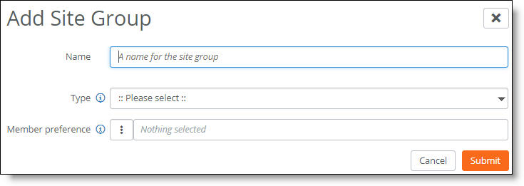
3. Specify a name for the site group that will contain the two split sites.
4. After Type, select Split Site from the drop-down list.
5. After Member preference, select the primary site. Take care when selecting the site, as site priority is based on the position of the individual sites in the member preference list from top to bottom. The first site selected has the highest priority, and the second site selected has the second highest priority.
The sites are deployed in active and backup mode. The primary site in the site group is the active site, and the second site in the site group provides a backup.
–We recommend that the first and second sites deploy the same hardware to provide equal sizing capacity for backup traffic processing in the event of a site failover.
–A site can only be part of one split site group.
–A site can be part of multiple dual-hub groups.
When selecting a site’s priority, take care to align the deployment with the underlay routing configuration to ensure a symmetric traffic flow.
–To reverse the primary and backup hub preference, select the hub group and click Edit. Click the up and down arrows to change the preference order.
–The site member preference overrides path preference when traffic moves to a backup site only when the primary (or active) site is completely unreachable. For details on path preference, see
Directing traffic using traffic rules.
6. Select the secondary site. Traffic for the sites will be shifted from the primary site to the backup site if the primary site fails. Both the primary site and the secondary site must have eBGP dynamic routing enabled on the uplinks to this WAN.
A site group can currently support two sites.
7. Click Submit.
Configuring dual hubs and multi-hubs
SCM 2.10 and later enhance a hub-and-spoke (AutoVPN leaf mode) deployment with the ability to configure a primary and backup hub. The backup hub provides an alternate path for traffic sent across AutoVPN from a branch site to a hub site for redundancy. Dual hubs are supported on overlay topologies with spoke (leaf) sites connecting to more than one hub.
SCM 2.12 introduces multi-hub deployments that allow a leaf site to connect up to five sites: a dual-hub site (two regular hubs), and a maximum of three shared services hubs.
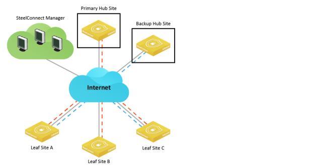
Dual-hub deployment
A dual-hub deployment provides a hub-and-spoke based network architecture rooted in two hub sites. A leaf site configured with a SteelConnect gateway as an edge device can connect to the two hub sites.
Redundant data centers are deployed into more than one site with primary and backup hubs for resilient connectivity, providing an active-passive topology for shared subnets. Leaf sites are dual homed into two hub sites with active-passive topology where a primary hub site failure will cause shared subnet traffic to be redirected to the backup hub site. The backup hub provides an alternate path for shared subnets.
For exclusive subnets that are only reachable through the backup hub, the traffic from a leaf site goes directly to the backup, providing a resilient active-active topology.
Dual-hub group
When you deploy a data center into more than one site, SCM regards each data center as a separate site. You can configure each data center site with its own attributes such as WAN uplink information, SDI-5030 gateway cluster tunnel endpoints (TEPs), and so on. After defining each site, you can form a data center site group that contains more than one data center. You can then prioritize the sites within the group by specifying a preference for any member of the group (which data center is 1, and which data center is 2). A lower number indicates a higher priority. By default, sites within a group use the same priority.
When a site is configured as leaf mode for a dual hub group, tunnels are built from that site to both hubs. Routing decisions are made based on priority.
An administrator can add and delete subnets from the data center site group and apply a single policy to all data centers in the group. Some examples of useful policies are policies that:
•correct asymmetrical routing.
•provide a deterministic path for traffic to flow on the overlay for a common subnet behind two sites.
•perform load balancing.
•enforce path quality.
Suppose you have two data centers using an SDI-5030 data center cluster to host the same services. Each spoke (leaf) site connects to two of the data centers for primary and backup hub redundancy. If connectivity to the primary hub goes down, the shared subnet traffic processing on the spoke (leaf) site fails over to the backup hub. If the primary hub tunnels come back online, traffic moves back to the primary hub.
For subnet traffic that can only be reached through the backup hub, the traffic from a leaf site goes directly to the backup hub.
Dual hubs are supported on SDI-1030, SDI-2030, and SDI-5030 gateways or SDI-VGW virtual gateways acting as the hub devices. You cannot configure an SDI-130 or SDI-330 gateway or a SteelHead SD appliance as a hub device.
When selecting sites to join a dual-hub group, do not add a site that has already been configured in leaf mode. Doing so will create an invalid design that has a negative impact on site pool generation. Suppose that you have three sites: site A, site B, and site C. The dual-hub group consists of sites A and B. Site A has been configured in leaf mode to site C. For this design, SteelConnect will not generate a site pool configuration for Site B.
All traffic is sent to the primary site in the hub group by default, irrespective of the WAN used.
When a traffic rule policy is configured with zone(s) as the source in a dual-hub deployment, the policy is applied only on the originating site (that is, where the zone actually exists). The traffic rule policy will not take effect on the second leg from the hub site to the destination.
Multi-hub deployment
A multi-hub deployment allows a leaf site to connect up to five sites: a dual-hub site (two regular hubs), and a maximum of three shared services hubs.
Multi-hub deployment
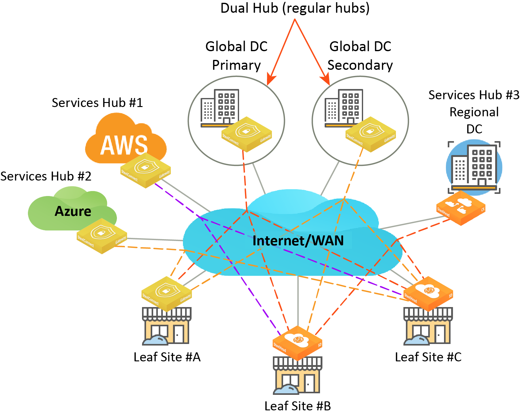
Shared services hubs provide access to their shared services to all connected leaf sites using bidirectional communication between themselves and the leaf sites. A shared services hub site can be a regional data center or an AWS/Azure cloud site that hosts services and applications. Unlike a regular (traditional) hub site, a shared services hub does not support spoke-to-spoke communication or any advanced transit hub or brownfield features.
A leaf site can directly communicate with a shared services hub site. A leaf site can communicate to other leaf sites only through regular hub sites. A site can either be used as a shared services hub or as a regular hub to a particular leaf site but not as both at the same time.
No redundancy is supported for shared services hubs. Only the regular dual hubs support redundancy.
These gateways and appliances are supported in a multi-hub deployment:
•Regular hubs - SteelConnect SDI-1030, SDI-2030, and SDI-5030 gateways, and SDI-VGW virtual gateways acting as the hub devices.
•Shared services hubs - SteelConnect SDI-1030, SDI-2030, and SDI-5030 gateways, SDI-VGW virtual gateways, AWS Cloud gateways, and Azure Cloud gateways.
•Leaf sites - SteelConnect SDI-130, SDI-330, SDI-1030, SDI-2030, and SDI-5030 gateways, SDI-VGW virtual gateways, and SteelHead SD 570-SD, 770-SD, 3070-SD appliances.
Configuring dual hubs and shared services hubs
You can configure a primary and backup hub group and shared services hubs using SCM.
To configure a dual-hub group and shared services hubs
1. Choose Network Design > Site Groups.
2. Click Add Site Group.
Site group
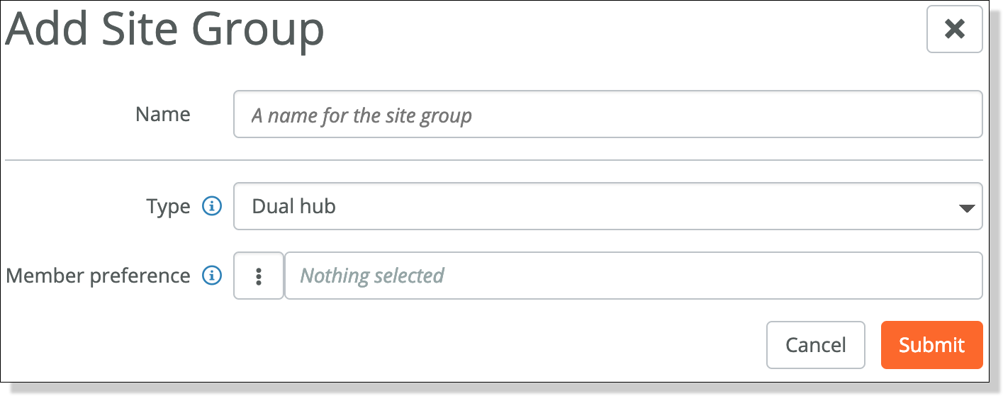
3. Specify a name for the hub group that will contain the primary and backup hub sites.
4. After Type, select Dual hub from the drop-down list.
5. After Member preference, select the primary hub site. Hub priority is based on the position of individual hubs in the member preference list from top to bottom. The first hub has the highest priority, and the second hub has the second highest priority. Traffic destined for subnets advertised from multiple hubs will be sent to the highest priority hub that has an established VPN connection with the spoke. The first member selection becomes the primary hub. The second member selection becomes the backup hub. When the primary hub has one or more tunnels online, traffic is sent to the primary hub.
The hub member preference overrides and takes priority over path preference when traffic moves to a backup hub only when the primary (or active) hub is completely unreachable. For details on path preference, see
Directing traffic using traffic rules.
6. Select the backup hub site. Traffic for the sites will be shifted from the primary hub to the backup hub if the primary hub fails.
–You must specify a primary and a backup hub.
–The primary and backup hub cannot be the same site.
–A site can be part of multiple dual-hub groups.
–A site can be part of only one site group and one or more dual-hub groups at a time.
–Do not select a site that has already been configured in leaf mode.
–We recommend that the primary and backup hub sites deploy the same gateway models to provide equal sizing capacity for traffic processing in the event of a hub failover.
–To reverse the primary and backup hub preference, select the hub group and click Edit. Click the up and down arrows to change the preference order.
Traffic never flows from the primary hub to the backup hub or vice versa. For example, suppose the traffic originates in a leaf site and is destined to a zone residing in the backup hub. In this situation, the traffic is sent directly to the backup hub.
7. To associate the branch sites with the primary and backup hub group, choose Network Design > Sites.
8. Select the first branch leaf site behind the primary hub.
9. Select the WAN/AutoVPN tab.
Creating a primary hub
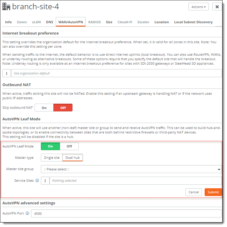
10. Make sure AutoVPN Leaf Mode is on.
11. After Master type, select Dual hub.
12. Select the master site group from the drop-down list.
13. To configure a multi-hub deployment, select up to three sites to interconnect with this leaf site as shared service hubs, in addition to two regular hubs.
15. Click Submit.