SteelFusion Appliance High-Availability Deployment
This chapter describes high-availability (HA) deployments for SteelFusion Core and SteelFusion Edge. It includes the following sections:
Storage availability
Applications of any type that read and write data to and from storage can suffer from three fundamental types of availability loss:
• Loss of storage
• Loss of access to the storage
• Loss of the data residing on the storage
As with a typical storage deployment, you might consider data HA and redundancy as a mandatory requirement rather than an option. Applications accessing data are always expecting the data, and the storage that the data resides on, to be available at all times. If for some reason the storage is not available, then the application ceases to function.
Storage availability is the requirement to protect against loss of access to stored data or loss of the storage in which the data resides. Storage availability is subtly different from data loss. In the case of data loss, whether due to accidental deletion, corruption, theft, or another event, you can recover the data from a snapshot, backup, or some other form of archive. If you can recover the lost data, it means that you previously had a process to copy data, either through snapshot, backup, replication, or another data management operation.
In general, the net effect of data loss or lack of storage availability is the same—loss of productivity. But the two types of data loss are distinct and addressed in different ways.
The subject of data availability in conjunction with the SteelFusion product family is documented in a number of white papers and other documents that describe the use of snapshot technology and data replication as well as backup and recovery tools. To read the white papers, go to Riverbed Community at
https://community.riverbed.com.Note: Core HA and Edge HA are independent from each other. You can have Core HA with no Edge HA, and vice versa.
Core high availability
You can deploy a Core as a single, stand-alone implementation; however, we strongly recommend that you always deploy the Core as pairs in an HA cluster configuration. The storage arrays and the storage area network (SAN) the Core attaches to are generally deployed in a redundant manner.
For more information about Core HA clusters, see
Core HA concepts. For more information about single-appliance implementation, see
Single-appliance deployment.
Core HA concepts
A pair of Cores deployed in an HA-failover cluster configuration are active-active. Each Core is the primary to itself and secondary to its peer. Both peers in the cluster are attached to storage in the data center. But individually they each are responsible for projecting one or more exports to one or more Edge appliances in branch locations.
Each Core is configured separately for the exports and the Edges it is responsible for. By default in a Core HA deployment, all exports are automatically configured for failover. .
As part of the HA deployment, you configure each Core with the details of its failover peer. This deployment comprises two IP addresses of network interfaces called failover interfaces. These interfaces are used for heartbeat and synchronization of the peer configuration. After the failover interfaces are configured, the failover peers use their heartbeat connections (failover interfaces) to share the details of their storage configuration. This information includes the exports they are responsible for and the Edges they are projecting the exports to.
If either peer fails, the surviving Core can take over control of the exports from the failed peer and continue projecting them to the Edges. During a failover scenario, all projected exports are set to read-only by the Core. The Edges will absorb writes locally in the blockstore and acknowledge, but commits will be paused until the failed Core recovers.
Core HA failover is triggered at the Core level. If an Edge loses connection to its primary Core, but still has connectivity to the secondary Core, no failover occurs. No failover occurs because both Cores continue to detect each other's heartbeat through the failover interfaces. The Edge enters a disconnected operations state as normal and saves write operations to the blockstore until connectivity to the primary Core is restored.
Note: Make sure that you size both failover peers correctly so that they have enough capacity to support the other Core storage in the event of a peer failure. If the surviving peer does not have enough resources (CPU and memory), then performance might degrade in a failure situation.
After a failed Core has recovered, the failback is automatic.
NFS file servers with virtual IP (VIP) support
In addition to the operational and hardware redundancy provided by the deployment of Core clusters, you can also cater to network redundancy. When connecting to a file server using NFS, it is possible that the file server supports the use of a virtual IP (VIP) address.
The VIP floats between the network interfaces on file servers that are part of an HA deployment. Clients that are accessing file servers using NFS in an HA deployment are configured to use the VIP address. When a file server that is part of an HA configuration is active, only it responds to the client requests. If the active file server fails for some reason, the standby file server starts responding to the client requests via the same VIP address.
Configuring HA for Core
This section describes best practices and the general procedure for configuring high availability between two Cores.
Note: Core HA configuration is independent of Edge HA configuration.
This section contains the following topics:
Cabling and connectivity for clustered Cores
Figure: Basic topology for Core HA shows an example of a basic HA topology including details of the different network interfaces used.
Note: Use crossover cables for connecting ports in clustered Cores.
Figure: Basic topology for Core HA
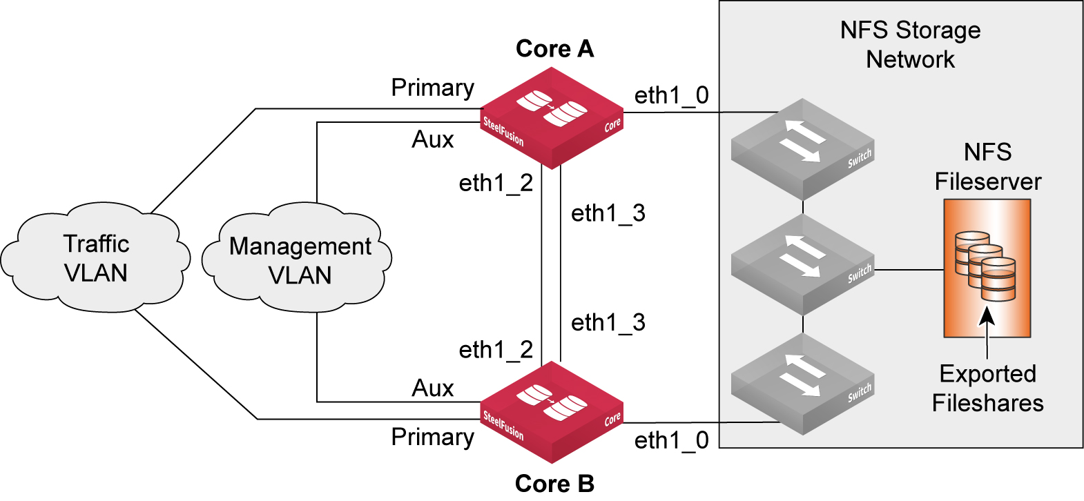
In the scenario shown in
Figure: Core HA failover interface design, both Cores (Core A and Core B) connect to the file server through their respective eth1_0 interfaces. The Cores communicate between each other using the failover interfaces that are configured as eth1_2 and eth1_3. Their primary interfaces are dedicated to the traffic VLAN that carries data to and from Edge appliances. The auxiliary interfaces are connected to the management VLAN and used to administer the Cores.
You can administer a Core from any of its configured interfaces assuming they are reachable. Use the AUX interface as a dedicated management interface rather than using one of the other interfaces that might be in use for storage data traffic.
When it is practical, use two dedicated failover interfaces for the heartbeat. Connect the interfaces through crossover cables and configure them using private IP addresses. This connection minimizes the risk of a split-brain scenario in which both Core peers consider the other to have failed. Directly connected, dedicated interfaces might not be possible for some reason. If the dedicated connections need to go through some combinations of switches and/or routers, they must use diverse paths and network equipment to avoid a single point of failure.
If you cannot configure two dedicated interfaces for the heartbeat, then an alternative is to specify the primary and auxiliary interfaces. Consider this option only if the traffic interfaces of both Core peers are connecting to the same switch or are wired so that a network failure means one of the Cores loses connection to all Edge appliances.
You can configure Cores with additional NICs to provide more network interfaces. These NICs are installed in PCIe slots within the Core. Depending on the type of NIC you install, the network ports could be 1-Gb Ethernet or 10-Gb Ethernet. In either case, you can use the ports for storage (NFS) traffic or heartbeat connectivity. The ports are identified as ethX_Y where X corresponds to the PCIe slot (from 1 to 5) and Y refers to the port on the NIC (from 0 to 3 for a four-port NIC and from 0 to 1 for a two-port NIC).
For more information about Core ports, see
Core interface and port configuration.
When using multiple interfaces for storage connectivity in an HA deployment, all interfaces should match in terms of their capabilities. Therefore, avoid mixing combinations of 1 Gb and 10 Gb for storage connectivity.
Configuring failover peers
You configure Core high availability by choosing Configure > Failover: Failover Configuration. To configure failover peers for Core, you need to provide the following information for each of the Core peers:
• The IP address of the peer appliance
• The local failover interface through which the peers exchange and monitor heartbeat messages
• An additional IP address of the peer appliance
• An additional local failover interface through which the peers exchange and monitor heartbeat messages
Figure: Core HA failover interface design shows an example deployment with failover interface IP addresses. You can configure any interface as a failover interface, but to maintain some consistency we recommend that you configure and use eth1_2 and eth1_3 as dedicated failover interfaces.
Figure: Core HA failover interface design
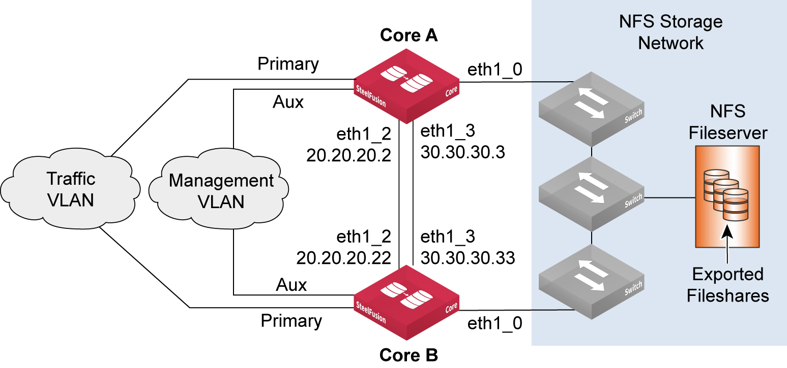
Figure: Core Failover Configuration page 1 shows the Failover Configuration page for Core A in which the peer is Core B. The failover interface IP addresses are 20.20.20.22 and 30.30.30.33 through interfaces eth1_2and eth1_3 respectively. The page shows eth1_2 and eth1_3 selected from the Local Interface drop-down list and the IP addresses of Core B interfaces are completed. Also in the Configuration page you can select the interface you want to use for connections from the failover peer Edge appliances.
Figure: Core Failover Configuration page 1
After you click
Enable Failover, the Core attempts to connect through the failover interfaces sending the storage configuration to the peer. If successful, you see the Device Failover Settings as shown in
Figure: Core HA Failover Configuration page 2.
Figure: Core HA Failover Configuration page 2
After the Core failover has been successfully configured, you can log in to the Management Console of the peer Core and view its Failover Configuration page.
Figure: Core HA Peer Failover configuration page 3 shows that the configuration page of the peer is automatically configured with the relevant failover interface settings from the other Core.
Figure: Core HA Peer Failover configuration page 3
Even though the relevant failover interfaces are automatically configured on the peer, you must configure the peer Preferred Interfaces for Edge Connections. By default, the primary interface is selected.
For more information about HA configuration settings, see the SteelFusion Core User Guide.
In the Core CLI, you can configure failover using the device-failover peer and device-failover peerip commands. To display the failover settings use the show device-failover command. For more information, see the SteelFusion Command-Line Interface Reference Manual.
If the failover configuration is not successful, then details are available in the Core log files and a message is displayed in the user interface. The failure can be for any number of different reasons. Some examples, along with items to check, are as follows:
• Unable to contact peer - Check the failover interface configurations (IP addresses, interface states and cables).
• Peer is already configured as part of a failover pair - Check that you have selected the correct Core.
• The peer configuration includes one or more exports that are already assigned to the other Core in the failover pair - Check the export assignments and correct the configuration.
• The peer configuration includes one or more Edge appliances that are already assigned to the other Core in the failover pair - Check the Edge assignments and correct the configuration.
After the failover configuration is complete and active, the configurations of the two peers in the cluster are periodically exchanged through a TCP connection using port 7971 on the failover interfaces. If you change or save either Core configuration, the modified configuration is sent to the failover peer. In this way, each peer always has the latest configuration details of the other.
You configure any Edge that is connecting to a Core HA configuration with the primary Core details (hostname or IP). After connected to the primary Core, the Edge is automatically updated with the peer Core information. This information ensures that during a Core failover situation in which an Edge loses its primary Core, the secondary Core can signal the Edge that it is taking over. The automatic update also minimizes the configuration activities required at the Edge regardless of whether you configure Core HA or not.
Accessing a failover peer from a Core
When you configure a Core for failover with a peer Core, all storage configuration pages include an additional feature that enables you to access and modify settings for both the current appliance you are logged in to and its failover peer.
You can use a drop-down list below the page title to select Self (the current appliance) or Peer. The page includes the message Device Failover is enabled, along with a link to the Failover Configuration page.
Figure: Failover-enabled feature on Storage Configuration page shows two sample Core management user interface screenshots of Manage > SteelFusion Edges pages: one without HA enabled and one with HA enabled, showing the drop-down list.
Figure: Failover-enabled feature on Storage Configuration page
Note: Because you can change and save the storage configuration settings for the peer in a Core HA deployment, ensure that any configuration changes are made for the correct Core.
Additionally, the Core storage report pages include a message that indicates when device failover is enabled, along with a link to the Failover Configuration page. You must log in to the peer Core to view the storage report pages for the peer.
Failover states and sequences
At the same time as performing their primary functions associated with projecting exports, each Core in an HA deployment is using its heartbeat interfaces to check if the peer is still active. By default, the peers check each other every 3 seconds through a heartbeat message. The heartbeat message is sent through TCP port 7972 and contains the current state of the peer that is sending the message.
The state is one of the following:
• ActiveSelf - The Core is healthy, running its own configuration and serving its exports as normal. It has an active heartbeat with its peer.
• ActiveSolo - The Core is healthy but the peer is down. It is running its own configuration and that of the failed peer. It is serving its exports and also the exports of the failed peer. The exports transition to read-only mode.
• Inactive - The Core is healthy but has just started up and cannot automatically transition to ActiveSolo or ActiveSelf. Typically this state occurs if both Cores fail at the same time. To complete the transition, you must manually activate the correct Core. For more information, see
Recovering from failure of both Cores in HA configuration.
• Passive - The default state when Core starts up. Depending on the status of the peer, the Core state transitions to Inactive, ActiveSolo, or ActiveSelf.
If there is no response from three consecutive heartbeats, then the secondary Core declares the primary failed and initiates a failover. Both Cores in an HA deployment are primary for their own functions and secondary for the peer. Therefore, whichever Core fails, it is the secondary that takes control of the exports from the failed peer.
Figure: Core ports used in HA - NFS deployment
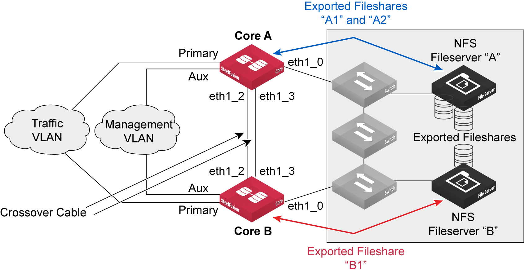
Core A and Core B are interconnected with two cross-over cables that are providing connectivity for heartbeat.
There are two NFS file servers: A and B. Although they could each be configured with virtual IP addresses to provide redundancy, it is not shown in the diagram for reasons of simplicity. File server A is exporting two fileshares, A1 and A2, which are mounted by Core A. File server B is exporting one fileshare, B1, which is mounted by Core B.
Again, for simplicity, no Edge devices are shown in the diagram, but for this example we can assume that an Edge has been configured to connect to Core A in order to map fileshares A1 and A2, and another Edge has been configured to connect to Core B in order to map projected fileshare B1.
Under normal conditions, where Core A and Core B are healthy, they are designed to operate in an “active-active” methodology. They are each in control of their respective fileshares, but also aware of their peer’s fileshares. They are independently servicing read and write operations to and from the Edge for their respective fileshares.
The Cores check each other via their heartbeat interfaces to ensure their peer is healthy. In a healthy state, both peers are reported as being ActiveSelf.
When a failover scenario occurs in a SteelFusion Core HA with NFS, the surviving Core transitions to the “ActiveSolo” state.
In this condition, the surviving Core transitions all exported fileshares that are part of the HA configuration and projected to Edges, into a read-only mode. In our example, this would include A1, A2, and B1.
Important: The “read-only mode” transition is from the perspective of the surviving Core and any Edges that are connected to the HA pair. There is no change made to the state of the exported fileshares on the backend NFS file servers. They remain in read-write mode.
With the surviving Core in ActiveSolo state and the NFS exports in read-only mode, the following scenarios apply:
• The ActiveSolo Core will defer all commits arriving from its connected Edges.
• The ActiveSolo Core will defer all snapshot requests coming in from its connected Edges.
• Edges connected to the ActiveSolo Core will absorb writes locally in the blockstore and acknowledge, but commits will be paused.
• Edges connected to the ActiveSolo Core will continue to service read requests locally if the data is resident in the blockstore, and will request nonresident data via the ActiveSolo Core as normal.
• Pinning and prepopulation of exported fileshares will continue to operate.
• Mounting new exported fileshares on the ActiveSolo Core from backend NFS file servers are permitted.
• Mapping exported fileshares from the ActiveSolo Core to Edge appliances will still be allowed.
• Any operation to offline an exported fileshare will be deferred.
• Any operation on backend NFS file servers to resize an exported fileshare will be deferred.
Once the failed SteelFusion Core in an HA configuration comes back online and starts communicating healthy heartbeat messages to the ActiveSolo Core, recovery to normal service is automatic. Both Core appliances return to an ActiveSelf state and exported fileshares are transitioned back to read-write mode.
All pending commits for the connected Edge appliances will be completed and any other deferred operations will resume and complete.
Note: In circumstances where it is absolutely necessary, it is possible to “force” a transition back to read-write mode while in an ActiveSolo state. Contact Riverbed Support for assistance if you need to perform this task.
If a Core that is part of an HA deployment needs to be replaced, see
“Replacing a Core in an HA deployment” on page 115 for further guidance.
Recovering from failure of both Cores in HA configuration
You can have a scenario in which both Cores in an HA configuration fail at the same time; for example, a major power outage. In this case, there is no opportunity for either Core to realize that its peer has failed.
When both Core appliances reboot, each peer knows that it has failed but does not have status from the other to say that it had been in an ActiveSolo state. Therefore, both Cores remain in the Inactive state. This state ensures that neither Core is projecting exports until you manually activate the correct Core. To activate the correct Core, choose Configure > Failover: Failover Configuration and select Activate Config.
After you activate the correct Core, it transitions to ActiveSolo. Both Core appliances transition to ActiveSelf.
Removing Cores from an HA configuration
This section describes the procedure for removing two Cores from their failover configuration.
To remove Cores from an HA configuration (basic steps)
1. Force one of the Cores into a failed state by stopping its service.
2. Disable failover on the other Core.
3. Start the service on the first Core again.
4. Disable the failover on the second Core.
You can perform these steps using either the Management Console or the CLI.
Figure: Example configuration of Core HA deployment shows an example configuration.
Figure: Example configuration of Core HA deployment
1. From the Management Console of Core A, choose Settings > Maintenance: Service.
2. Stop the Core service.
3. From the Management Console of Core B, choose Configure > Failover: Failover Configuration.
4. Click Disable Failover.
5. Return to the Management Console of Core A, and choose Settings > Maintenance: Service.
6. Start the Core service.
7. From the Management Console of Core A, choose Configure > Failover: Failover Configuration.
8. Click Disable Failover.
9. Click Activate Local Configuration.
Core A and Core B are no longer operating in an HA configuration.
1. Connect to the CLI of Core A and enter the following commands to stop the Core service:
enable
configure terminal
no service enable
2. Connect to the CLI of Core B and enter the following commands to clear the local failover configuration:
enable
configure terminal
device-failover peer clear
write memory
3. Return to the CLI of Core A and enter the following commands to start the Core service, clear the local failover configuration, and return to nonfailover mode:
enable
configure terminal
service enable
device-failover peer clear
device-failover self-config activate
write memory
Core A and Core B are no longer operating in an HA configuration.
Edge high availability
The SteelFusion Edge appliance presents itself as an NFS file server for exports to ESXi hypervisors in one or both of the following modes:
• Storage is resident in the RiOS node and is accessed using NFS externally to the appliance by the hypervisor node. In this mode, the hypervisor running in the hypervisor node is acting as the NFS client.
• Storage is accessed using NFS on a hypervisor host that is external to the SteelFusion Edge.
In the unlikely event of failure or a scheduled loss of service due to planned maintenance, you may need an alternative way to access the storage and ensure continued availability of services in the branch. Deploying two SteelFusion Edges in a high availability (HA) configuration enables this access.
This section describes HA deployments for the SteelFusion Edge appliance. It contains the following topics:
Note: This guide requires you to be familiar with the SteelFusion Edge User Guide.
Using the correct interfaces for SteelFusion Edge deployment
This section reviews the network interfaces on SteelFusion Edge and how you can configure them. For more information about Edge network interface ports, see
SteelFusion Edge ports.
By default, all Edge appliances are equipped with the following physical interfaces:
• Primary, Auxiliary, eth0_0, eth0_1, lan1_0, wan1_0, lan1_1, wan1_1 - These interfaces are owned and used by the RiOS node in Edge.
• gbe0_0, gbe0_1, gbe0_2, gbe0_3 - These interfaces are owned and used by the hypervisor node in Edge.
Traditionally in an Edge appliance, the LAN and WAN interface pairs are used by the RiOS node as an in- path interface for WAN optimization. The primary and auxiliary interfaces are generally used for management and other services.
In an Edge HA deployment, the eth0_0 and eth0_1 interfaces are used for the heartbeat interconnect between the two SteelFusion Edge HA peers. If there is only a single Edge deployed in the branch, then you can use eth0_0 and eth0_1 as data interfaces for NFS traffic to and from servers in the branch that are external to the Edge.
While there are many additional combinations of port usage, you can generally expect that NFS traffic to and from external ESXi servers in the branch use the primary interface. Likewise, the Rdisk traffic to and from the Core uses the primary interface by default and is routed through the SteelFusion Edge in-path interface. The Rdisk traffic gains some benefit from WAN optimization. Management traffic for the Edge typically uses the auxiliary interface.
For the hypervisor node, you can use the gbe0_0 to gbe0_3 interfaces for general purpose LAN connectivity within the branch location. These interfaces enable clients to access services running in virtual machines installed on the hypervisor node. These interfaces are also used by the hypervisor node to connect to the NFS file server exports in the RiOS node.
Figure: Basic interface configuration for SteelFusion Edge with external ESXi servers shows a basic configuration example for Edge deployment where the ESXi server is external to the Edge. The SteelFusion Edge traffic flows for Rdisk and NFS traffic are shown. The virtual IP (VIP) of the NFS file server is also indicated.
Figure: Basic interface configuration for SteelFusion Edge with external ESXi servers
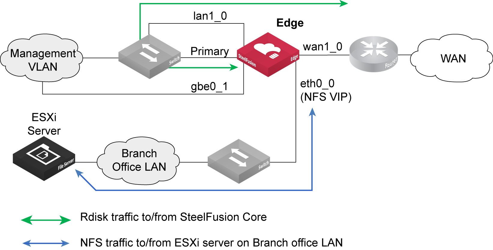
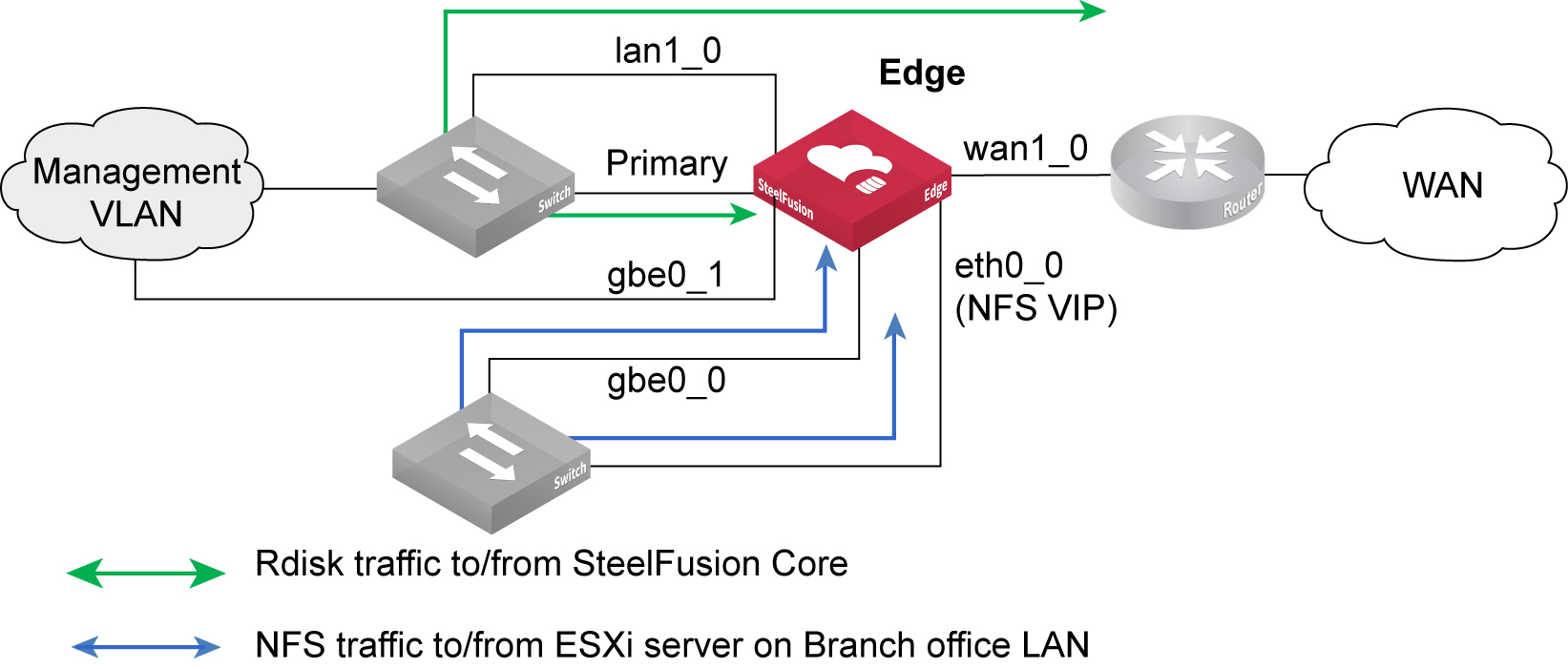
Figure: Basic interface configuration for Edge with servers hosted in hypervisor node shows a basic configuration example for Edge deployment where the ESXi server is hosted inside the hypervisor node of Edge. The SteelFusion Edge traffic flows for Rdisk and NFS traffic are shown. The virtual IP (VIP) of the NFS file server is also indicated. Remember that even though the NFS file server and hypervisor are both internal to Edge, the NFS connection between the RiOS node and the hypervisor node is external.
Figure: Basic interface configuration for Edge with servers hosted in hypervisor node
We recommend that you make full use of all the connectivity options available in the appliance for production deployments of Edge. Careful planning can ensure that important traffic, such as NFS traffic to external servers, Rdisk to and from the Core, and blockstore synchronization for high availability, are kept apart from each other. This separation helps with ease of deployment, creates a more defined management framework, and simplifies any potential troubleshooting activity.
Depending on the model, Edge can be shipped or configured in the field with one or more additional multiple-port network interface cards (NICs). There is a selection of both copper and optical 1-GbE and 10-GbE NICs that fall into one of two categories. The two categories are bypass cards suitable for use as in-path interfaces for WAN optimization or data cards suitable for LAN connectivity.
In the case of LAN connectivity, the data cards might be for any of the following examples:
• NFS traffic to and from ESXi servers in the branch that are external to SteelFusion Edge.
• Application traffic from clients in the branch connecting to application servers hosted in the Edge hypervisor node.
• Additional LAN connectivity for redundancy purposes (for example, SteelFusion Edge HA, and so on).
You cannot change the mode of the NIC from data to in-path or vice versa. For a complete list of available NICs, their part numbers and installation details, see SteelFusion Edge Hardware and Maintenance Guide.
Choosing the correct cables
The LAN and WAN ports on the SteelFusion Edge bypass cards act like host interfaces during normal operation. During fail-to-wire mode, the LAN and WAN ports act as the ends of a crossover cable. Using the correct cable to connect these ports to other network equipment ensures proper operation during fail-to-wire mode and normal operating conditions. This cabling is especially important when you are configuring two SteelFusion Edge appliances in a serial in-path deployment for HA.
We recommend that you do not rely on automatic MDI/MDI-X to automatically sense the cable type. The installation might be successful when the SteelFusion Edge is optimizing traffic, but it might not be successful if the in-path bypass card transitions to fail-to-wire mode.
One way to help ensure that you use the correct cables during an installation is to connect the LAN and WAN interfaces of the bypass card while the SteelFusion Edge is powered off. This configuration proves that the devices on either side of the appliance can communicate correctly without any errors or other problems.
In the most common in-path configuration, a SteelFusion Edge LAN port is connected to a switch and the SteelFusion Edge WAN port is connected to a router. In this configuration, a straight-through Ethernet cable can connect the LAN port to the switch, and you must use a crossover cable to connect the WAN port to the router.
When you configure SteelFusion Edge in HA, it is likely that you have one or more additional data NICs installed into the appliance to provide extra interfaces. You can use the interfaces for blockstore synchronization.
This table summarizes the correct cable usage in the SteelFusion Edge when you are connecting LAN and WAN ports or when you are connecting data ports.
Devices | Cable |
SteelFusion Edge to SteelFusion Edge | Crossover |
SteelFusion Edge to router | Crossover |
SteelFusion Edge to switch | Straight-through |
SteelFusion Edge to host | Crossover |
Overview of SteelFusion Edge HA
This section describes HA features, design, and deployment of SteelFusion Edge. You can assign the exports provided by Edge (which are projected from the Core in the data center) in a variety of ways. Whether used as a datastore for VMware ESXi in the hypervisor node, or for other hypervisors and discrete servers hosted externally in the branch office, the exports are always served from the Edge using the NFS protocol.
Because of the way the exports are served, you can achieve HA with Edge by using the following :
This option is independent of any HA Core configuration in the data center that is projecting one or more exports to the Edge. However, because of different Edge deployment options and configurations, there are several scenarios for HA. For example, you can consider hardware redundancy consisting of multiple power supplies or RAID inside the Edge appliance as a form of HA. For more information about hardware, see the product specification documents.
Alternatively, when you deploy two Edge appliances in the branch, you can configure the VSP on both devices to provide an active-passive capability for any VMs that are hosted on the hypervisor node. In this context, HA is purely from the point of view of the VMs themselves, and there is a separate Edge providing a failover instance of the hypervisor node.
For more details about how to configure Edge HA, see the SteelFusion Edge User Guide.
SteelFusion Edge HA using blockstore synchronization
To survive a failure of the SteelFusion Edge without downtime, you must deploy a second appliance. If you configure two appliances as an HA pair, the SteelFusion Edge can continue serving exports without disruption to the servers in the branch, even if one of the SteelFusion Edge appliances were to fail. The serving of exports in a SteelFusion Edge HA deployment can be used by the VSP of the second SteelFusion Edge and by external servers within the branch office.
The scenario described in this section has two SteelFusion Edges operating in an active-standby role. This scenario is irrespective of whether the Core is configured for HA in the data center.
The active SteelFusion Edge is connected to the Core in the data center and is responding to the read and write requests for the exports it is serving in the branch. This method of operation is effectively the same as with a single SteelFusion Edge; however, there are some additional pieces that make up a complete HA deployment.
Note: If you plan to configure two SteelFusion Edge appliances into an HA configuration at a branch, we strongly recommend you do this configuration at the time of installation. Adding a second SteelFusion Edge to form an HA pair at a later date is possible but is likely to result in disruption to the branch services while the reconfiguration is performed.
The standby SteelFusion Edge does not service any of the read and write requests but is ready to take over from the active peer.
As the server writes new data to exports through the blockstore of the active SteelFusion Edge, the data is reflected synchronously to the standby peer blockstore. When the standby peer has acknowledged to the active peer that it has written the data to its own blockstore, the active peer then acknowledges the server. In this way, the blockstores of the two SteelFusion Edges are kept in lock step.
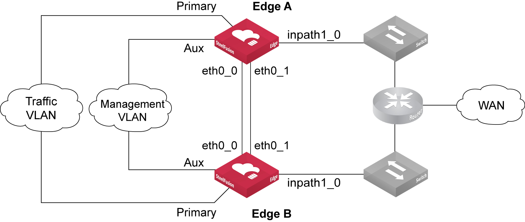
Figure: Basic topology for SteelFusion Edge high availability illustrates a basic HA configuration for SteelFusion Edge. While this figure is a very simplistic deployment diagram, it highlights the importance of the best practice to use two dedicated interfaces between the SteelFusion Edge peers to keep their blockstores synchronized. We strongly recommend you configure the SteelFusion Edges to use eth0_0 and eth0_1 as their interfaces for synchronization and failover status. Using dedicated interfaces through crossover cables ensures that a split-brain scenario (in which both peer devices think the other has failed and start serving independently) is minimized.
Figure: Basic topology for SteelFusion Edge high availability
Prior to SteelFusion 4.2 software, although two interfaces are configured, only one interface is actively sending blockstore synchronization traffic. In SteelFusion 4.2 and later, the Edge software includes Multipath NetDisk. With this new feature, you can load balance the blockstore synchronization traffic across both interfaces. Multipath NetDisk continues to provide resiliency for the blockstore synchronization but also delivers higher performance. You do not need to do any additional configuration to enable this capability if both Edges are running SteelFusion 4.2 .
If the interfaces used for blockstore synchronization are of different capacities (for example, one is 1 Gbps and the other is 10 Gbps), then we recommend that you specify the higher capacity interface first.
For more configuration details, see the SteelFusion Edge User Guide.
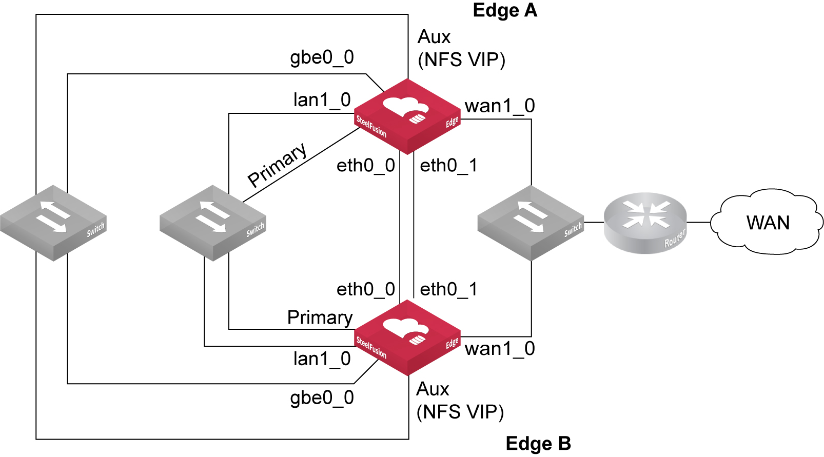
SteelFusion Edge high availability with NFS
Figure: Ports used in Edge HA NFS/file deployment - external ESXi server
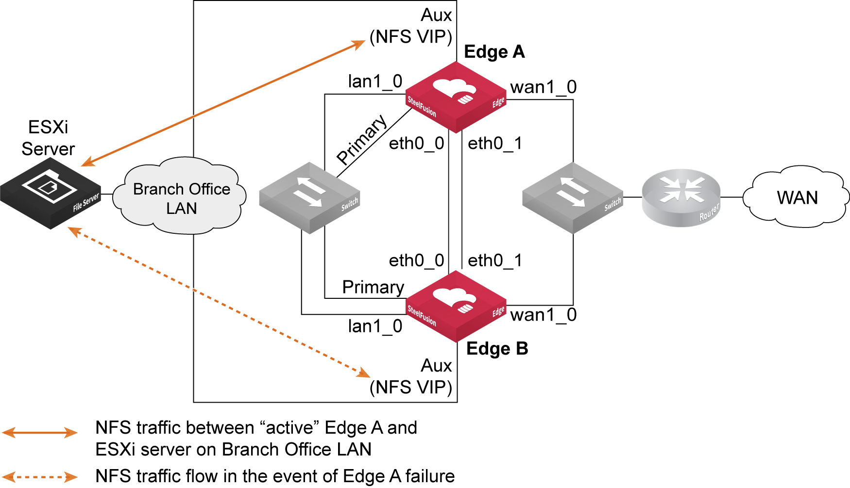
The basic example design shown in
Figure: Ports used in Edge HA NFS/file deployment - external ESXi server is intended to illustrate the connectivity between the Edge peers (Edge A and Edge B). In this example, the ESXi server is located on the branch office LAN, external from the SteelFusion Edge appliances. In a production HA design, there will most likely be additional routing and switching equipment, but for simplicity in the diagram, this is not included. See also
Figure: Ports used in Edge HA NFS/file deployment - ESXi server in hypervisor node for an example of a basic design where the ESXi server is located within the Edge hypervisor node.
Best practice is to connect both Edge appliances using eth0_0 and eth0_1 network interfaces for heartbeat and blockstore sync.
When configured as an HA pair, the Edges operate in an active-standby mode. Both Edge appliances are configured with the virtual IP (VIP) address. The underlying interface on each Edge (the example in
Figure: Ports used in Edge HA NFS/file deployment - external ESXi server is using the auxiliary port) must be configured with an IP on the same subnet.
The ESXi server is configured with the VIP address for the NFS file server of the Edge HA pair. In their active-standby roles, it is the active Edge that responds via the VIP to NFS read/write requests from the ESXi server. It is also the active Edge that is communicating with the attached Core to send and receive data across the WAN link. The standby Edge takes no part in any communication other than to send/receive heartbeat messages and synchronous blockstore updates from the active Edge.
If the active Edge fails, the standby Edge takes over and begins responding to the ESXi server via the same VIP on its interface.
For more details about the communication between Edge HA peers, see
SteelFusion Edge HA peer communication.Figure: Ports used in Edge HA NFS/file deployment - ESXi server in hypervisor node shows another basic Edge HA design, but in this case, the ESXi server is located in the hypervisor node of the Edge. Remember that in an NFS/file deployment with Edge, communication between the NFS file server in the SteelFusion Edge RiOS node and the ESXi server in the hypervisor node is performed externally via suitable network interfaces.
Figure: Ports used in Edge HA NFS/file deployment - ESXi server in hypervisor node
In this example, the NFS file server is accessible via the VIP address configured on the auxiliary (Aux) port and connects to the hypervisor node using the gbe0_0 network interface port.
The option to configure the VSP on both Edge appliances to provide an active-passive capability for any virtual machines (VMs) hosted on the hypervisor node is also possible with Edge NFS/file deployments.
For more details about how to configure Edge HA, see the SteelFusion Edge User Guide.
SteelFusion Edge HA peer communication
When you configure two SteelFusion Edges as active-standby peers for HA, they communicate with each other at regular intervals. The communication is required to ensure that the peers have their blockstores synchronized and that they are operating correctly based on their status (active or standby).
The blockstore synchronization happens through two network interfaces that you configure for this purpose on the SteelFusion Edge. Ideally, these are dedicated interfaces, preferably connected through crossover cables. Although not the preferred method, you can send blockstore synchronization traffic through other interfaces that are already being used for another purpose. If interfaces must be shared, then avoid using the same interfaces for both NFS traffic and blockstore synchronization traffic. These two types of traffic are likely to be quite intensive. Instead, use an interface that is more lightly loaded: for example, management traffic.
The interfaces used for the actual blockstore synchronization traffic are also used by each peer to check the status of one another through the heartbeat messages. The heartbeat messages provide each peer with the status of the other peer and can include peer configuration details.
A heartbeat message is sent by default every 3 seconds through TCP port 7972. If the peer fails to receive three successive heartbeat messages, then a failover event can be triggered. Because heartbeat messages are sent in both directions between SteelFusion Edge peers, there is a worst-case scenario in which failover can take up to 18 (3 x 3 x 2) seconds.
Failovers can also occur due to administrative intervention: for example, rebooting or powering off a SteelFusion Edge.
The blockstore synchronization traffic is sent between the peers using TCP port 7973. By default, the traffic uses the first of the two interfaces you configure. If the interface is not responding for some reason, the second interface is automatically used.
If neither interface is operational, then the SteelFusion Edge peers enter into some predetermined failover state based on the failure conditions.
The failover state on a SteelFusion Edge peer can be one of the following:
• Discover - Attempting to establish contact with the other peer.
• Active Sync - Actively serving client requests; the standby peer is in sync with the current state of the system.
• Standby Sync - Passively accepting updates from the active peer; in sync with the current state of the system.
• Active Degraded - Actively serving client requests; cannot contact the standby peer.
• Active Rebuild - Actively serving client requests; sending the standby peer updates that were missed during an outage.
• Standby Rebuild - Passively accepting updates from the active peer; not yet in sync with the state of the system.
For detailed information about how to configure two SteelFusion Edges as active-standby failover peers, the various failover states that each peer can assume while in an HA deployment, and the procedure required to remove an active-standby pair from that state, see the SteelFusion Edge User Guide.
Recovering from split-brain scenarios involving Edge HA
Even though the communication between the peers of an Edge HA deployment is designed for maximum resiliency, there is a remote possibility of a failure scenario known as split brain. Split brain can occur if the heartbeat communication between the peers fails simultaneously in all aspects; that is, both heartbeat interfaces fail at the same time. If these interfaces are directly connected through cross-over cables then the possibility is extremely remote. But if the heartbeat interfaces are connected through network switches, then depending on the design and topology, split brain might occur.
In a split-brain condition, both Edge appliances act as if the peer has failed. This action can result in both peers being Active Degraded. Because both peers can be simultaneously trying to serve data and also be synchronizing data back through the Core, this action could lead to data integrity issues.
There are ways to recover from this scenario, but the best course of action is to contact Riverbed Support and open a support case. Any recovery process is likely to be different from another so the actual procedure may vary depending on the failure sequence.
Note: The recovery process can involve accessing a previous snapshot of the affected exports.
Testing HA failover deployments
There are many ways that you can test a failover configuration of Core HA or Edge HA. These tests may include power-cycling, SteelFusion HA peer device reboot, or any number of network connection failure scenarios (routers, switches, cables).
Your failover test should at least satisfy the basic requirements that ensure the SteelFusion HA deployment recovers as expected.
The simplest test is to perform an orderly reboot of a SteelFusion peer device (Core or Edge) that is one half of an HA configuration.
Configuring WAN redundancy
This section describes how to configure WAN redundancy. It includes the following topics:
You can configure multiple interfaces to provide a degree of redundancy across the WAN between the Core and the Edge. This redundancy ensures that any failure along the WAN path can be tolerated by the Core and the Edge, and is called WAN redundancy.
WAN redundancy provides multiple paths for connection in case the main Core to Edge link fails.
To configure WAN redundancy, you perform a series of steps on both the data center and branch side.
You can use both the in-path interfaces (inpathX_Y) or Ethernet interfaces (ethX_Y) for redundant WAN link configuration. In the examples below the term intf is used to imply either in-path or Ethernet network interfaces.
Configuring WAN redundancy with no Core HA
This section describes how to configure WAN redundancy when you do not have a Core HA deployment.
To configure WAN redundancy
1. Configure local interfaces on the Edge. The interfaces are used to connect to the Core:
• From the Edge Management Console, choose Storage > Storage Edge Configuration.
• Click Add Interface.
Figure: Edge
interfaces
2. Configure preferred interfaces for connecting to the Edge on the Core:
• From the Core Management Console, choose Configure > Manage: SteelFusion Edges.
• Select Show Preferred Interfaces for SteelFusion Edge Connections.
• Click Add Interface.
Figure: Adding Core interfaces
On first connection, the Core sends all the preferred interface information to the Edge. The Edge uses this information along with configured local interfaces to connect on each link (local-interface and preferred-interface pair) until a successful connection is formed. The Edge tries each connection three times (and waits 3 seconds before the next try) before it moves on to the next; that is, if the first link fails, the next link is tried in nine seconds.
After the Core and the Edge have established a successful alternative link, the Edge updates its Rdisk configuration with the change, so that the configuration is on the same link as the management channel between Core and Edge.
3. Remove the local interface for WAN redundancy on Edge:
• From the Edge Management Console, choose Storage > Storage Edge Configuration.
• Open the interface you want to remove.
• Click Remove Interface.
4. Remove preferred interfaces for WAN redundancy on the Core:
• From the Core Management Console, choose Configure > Manage: SteelFusion Edges.
• Select Show Preferred Interfaces for SteelFusion Edge Connections.
• Open the interface you want to remove.
• Delete the interface.
Any change in the preferred interfaces on the Core is communicated to the Edge and the connection is updated as needed.
Configuring WAN redundancy in an HA environment
In a Core HA environment, the preferred interfaces information of the failover Core is sent to the Edge by the primary Core. The connection between the Edge and the failover Core follows the same logic in which a connection is tried on each link (local interface and preferred interface pair) until a connection is formed.
Related information
• SteelFusion Core User Guide
• SteelFusion Edge User Guide
• SteelFusion Core Installation and Configuration Guide
• SteelFusion Command-Line Interface Reference Manual