Installing Cards in xx70, Interceptor 9600, and SteelFusion Core 3500 Appliances
This chapter describes how to install network and storage cards in SteelHead CX xx70, SteelHead Interceptor 9600, SteelFusion Core 3500, and SteelCentral xx70 appliances. It includes the following sections:
This chapter assumes you have installed and configured the appliance. For details, see the installation and configuration guide for your product.
Appliances Included in This Chapter
This chapter describes how to install cards in the following appliances:
• 1U xx70 appliances, including SteelHead CX3070, SteelCentral NetExpress 470, and SteelCentral NetShark 2170.
• 2U xx70 appliances, including SteelHead CX5070, SteelHead CX7070, SteelCentral NetProfiler 2270, SteelCentral NetProfiler 4270-EX, SteelCentral NetProfiler 4270-AN, SteelCentral NetShark 4170, and SteelCentral NetShark 6170.
• 2U SteelHead Interceptor 9600 appliances.
• 2U SteelFusion Core 3500 appliances.
For information about SteelFusion Edge appliances, see SteelFusion Edge Hardware Installation and Maintenance Guide.
Before You Begin
During installation, make sure you follow proper ESD procedures when you handle the NIC:
• Wear properly grounded ESD straps.
• If an ESD strap is not available, touch a properly grounded metallic surface prior to handling the NIC.
• Do not touch the electronic components on the NIC.
Before you install a NIC, ensure the card meets the software and appliance requirements described in the following sections.
Supported Cards for SteelHead CX xx70 and SteelHead Interceptor 9600 Appliances
This section describes the software requirements and cards that you can install on SteelHead CX xx70 and SteelHead Interceptor 9600 appliances.
All the network cards for the SteelHead and SteelHead Interceptor appliances support fail-to-block mode. For more information, see
Fail-to-Block Mode. The minimum software requirements for the CX xx70 NICs are RiOS 8.6.2 or RiOS 9.0.0b or later. The SteelHead Interceptor 9600 NICs require Interceptor 4.5.2 or later.
The following tables summarize the add-on cards compatible with the CX xx70 and Interceptor 9600 appliances.
SteelHead CX xx70
NICs | Size (*) | Manufacturing Part # | Orderable Part # | CX3070 | CX5070 | CX7070 |
Four-Port 1-GbE Copper Base-T | HHHL | 410-00115-01 | NIC-1-001G-4TX-BP | X | X | X |
Two-Port 1-GbE Fiber SX | HHHL | 410-00113-01 | NIC-1-001G-2SX-BP | X | X | X |
Four-Port 1-GbE Fiber SX | FHHL | 410-00122-01 | NIC-1-001G-4SX-BP | X | X | X |
Two-Port 1-GbE Fiber LX | HHHL | 410-00114-01 | NIC-1-001G-2LX-BP | X | X | X |
Four-Port 1-GbE Fiber LX | FHHL | 410-00123-01 | NIC-1-001G-4LX-BP | X | X | X |
Two-Port 10-GbE Fiber SR | FHHL | 410-00302-03 | NIC-1-010G-2SR-BP | X | X | X |
Two-Port 10-GbE Fiber LR | FHHL | 410-00301-03 | NIC-1-010G-2LR-BP | X | X | X |
5-Gbps Compression Offload Card | HHHL | 410-00303-02 | OFL-1-CMP-1 | | | X |
10-Gbps Compression Offload Card | FHHL | 410-00055-02 | OFL-1-CMP-2 | | | X |
* HHHL = Half Height, Half Length, FHHL = Full Height, Half Length
SteelHead Interceptor 9600
NICs | Size (*) | Manufacturing Part # | Orderable Part # | IC9600 |
Four-Port 1-GbE Copper Base-T | HHHL | 410-00115-01 | NIC-1-001G-4TX-BP | X |
Two-Port 1-GbE Fiber SX | HHHL | 410-00113-01 | NIC-1-001G-2SX-BP | X |
Four-Port 1-GbE Fiber SX | FHHL | 410-00122-01 | NIC-1-001G-4SX-BP | X |
Two-Port 1-GbE Fiber LX | HHHL | 410-00114-01 | NIC-1-001G-2LX-BP | X |
Four-Port 1-GbE Fiber LX | FHHL | 410-00123-01 | NIC-1-001G-4LX-BP | X |
Two-Port 10-GbE Fiber SR | FHHL | 410-00302-03 | NIC-1-010G-2SR-BP | X |
Two-Port 10-GbE Fiber LR | FHHL | 410-00301-03 | NIC-1-010G-2LR-BP | X |
* HHHL = Half Height, Half Length; FHHL = Full Height, Half Length
Supported Cards for SteelFusion Core 3500 Appliances
All the network cards for SteelFusion appliances support fail-to-block mode. (See
Fail-to-Block Mode. )
The minimum software requirements for the SteelFusion Core 3500 NICs require SteelFusion Core 4.0 or later. The Two-Port 10-GbE Fiber SFP+ card requires the SteelFusion Core 4.2 software version or later.
The following tables summarize the add-on cards and small form-factor pluggables (SFP) compatible with the SteelFusion Core 3500 appliances.
SteelFusion Core 3500
NICs | Size (*) | Manufacturing Part # | Orderable Part # | SFCR3500 |
Four-Port 1-G Copper | HHHL | 410-00115-01 | NIC-1-001G-4TX | X |
Four-Port 1-GbE Fiber/Copper SFP | HHHL | 410-00124-01 | NIC-1-001G-4SFP | X |
Two-Port 10-GbE Fiber SFP+ | HHHL | 410-00036-02 | NIC-1-010G-2SFPP | X |
Two-Port 10-GbE TX Copper | HHHL | 410-00094-01 | NIC-1-010G-2TX | X |
* HHHL = Half Height, Half Length
SFP | Manufacturing Part # | Orderable Part # | SFCR3500 |
SFP+ 10-GbE SR | 410-00143-01 | TRC-1-SFPP-SR | X |
SFP+ 10-GbE LR | 410-00144-01 | TRC-1-SFPP-LR | X |
Supported Cards for SteelCentral xx70 Appliances
All SteelCentral xx70 NICs require version 10.8 or later. The following tables summarizes the add-on cards compatible with the SteelCentral xx70 hardware appliances.
SteelCentral NetExpress and NetProfiler xx70
NICs | Size (*) | Manufacturing Part # | Orderable Part # | SCNE470 | SCNP2270 | SCNP4270
EX | SCNP4270AN |
Four-Port 1-GbE Fiber/Copper SFP | HHHL | 410-00124-01 | NIC-1-001G-4SFP | X | | | |
Four-Port 1-GbE Copper Base-T | HHHL | 410-00116-01 | NIC-1-001G-4TX | X | | | |
Two-Port 10-GbE Fiber SFP+ | HHHL | 410-00036-02 | NIC-1-010G-2SFPP | X | | | |
Two-Port FC HBA (SAN)
4/8/16-Gbps Emulex | HHHL | 410-00158-01 | NIC-1-HBA-2FC | | X | X | X |
Expander - PCIe Card | | 410-00152-01 | STC-1-EXP-P24 | | X | X | X |
* HHHL = Half Height, Half Length
SFP | Manufacturing Part # | Orderable Part # | SCNE470 |
SFP 1-GbE SX | 410-00139-01 | TRC-1-SFP-SX | X |
SFP 1-GbE LX | 410-00140-01 | TRC-1-SFP-LX | X |
SFP+ 10-GbE SR | 410-00143-01 | TRC-1-SFPP-SR | X |
SFP+ 10-GbE LR | 410-00144-01 | TRC-1-SFPP-LR | X |
SteelCentral NetShark xx70
NICs | Size (*) | Manufacturing Part # | Orderable Part # | SCAN-2170 | SCAN-4170 | SCAN-6170 |
Four-Port 1-GbE Fiber/Copper SFP | HHHL | 410-00124-01 | NIC-1-001G-4SFP | X | X | X |
Four-Port 1-GbE Copper Base-T | HHHL | 410-00116-01 | NIC-1-001G-4TX | X | X | X |
Two-Port 10-GbE Fiber SFP+ | HHHL | 410-00036-02 | NIC-1-010G-2SFPP | X | X | X |
Four-Port 10-GbE Fiber SFP+ | HHHL | 410-00108-01 | NIC-1-010G-4SFPP | | X | X |
8e (PCIe): Raid Controller PCIe Card (8 internal ports) | HHHL | 410-00169-01 | STC-1-RAC-P08-SP | | X | |
8e (PCIe): Raid Controller PCIe Card (8 external ports) | HHHL | 410-00157-01 | STC-1-RAC-P80 | | | X |
* HHHL = Half Height, Half Length
SFP | Manufacturing Part # | Orderable Part # | SCAN-2170 | SCAN-4170 | SCAN-6170 |
SFP 1-GbE SX | 410-00139-01 | TRC-1-SFP-SX | X | X | X |
SFP 1-GbE LX | 410-00140-01 | TRC-1-SFP-LX | X | X | X |
SFP+ 10-GbE DAC (Direct Attached Copper Twinax) | 410-00142-01 | TRC-1-SFPP-DAC | X | X | X |
SFP+ 10-GbE SR | 410-00143-01 | TRC-1-SFPP-SR | X | X | X |
SFP+ 10-GbE LR | 410-00144-01 | TRC-1-SFPP-LR | X | X | X |
Installing Cards in 1U Appliances
This section describes how to install cards in the 1U SteelHead CX and SteelCentral xx70 appliances.
The following figure identifies the slot locations. Due to space limitations, slot 1 only supports half-height, half-length cards. Slots 2 and 3 support full-height, full-length cards.
Figure: PCIe Slot Locations for 1U xx70 Appliances

SteelHead CX3070 appliances ship with a four-port 1-GbE copper bypass card installed in slot 3. These appliances have two additional slots for expansion.
SteelCentral NetExpress and SteelCentral NetProfiler support only one NIC.
SteelCentral NetShark 2170 supports only one NIC. The NIC must be installed in slot 2.
To prepare to install or replace a network card
1. Power down the appliance.
2. Remove the power-supply cord.
3. Remove the cables connected to the appliance.
4. Remove the appliance from the mounting rack, if necessary.
Figure: Removing the Appliance Cover
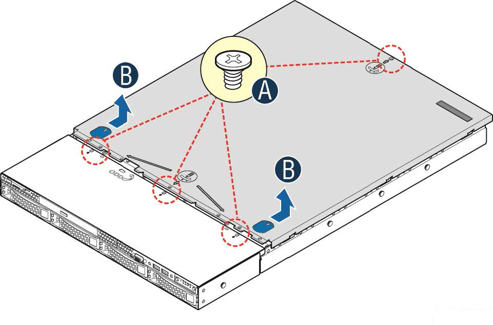
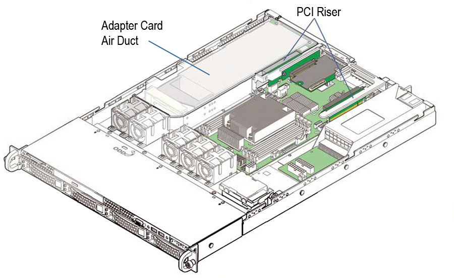
Figure: PCI Riser Slots and Adapter Card Air Duct
To install a low-profile PCIe card in slot 1
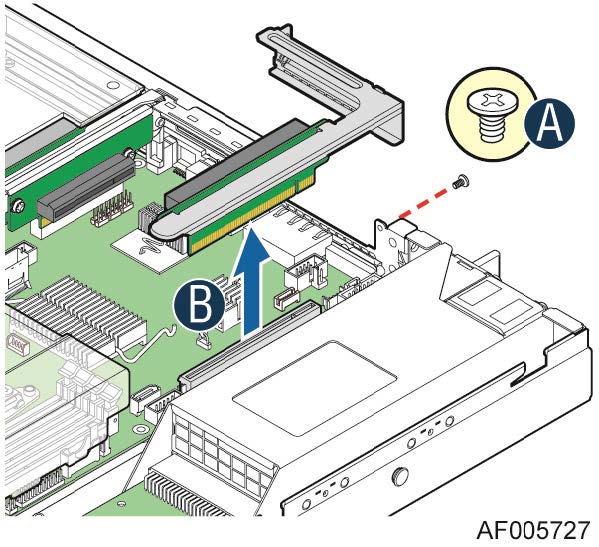
Figure: Removing the Riser with Bracket
2. If you are replacing an existing card, carefully pull the card from the riser. If you are not replacing a card, remove the filler panel from the slot by pushing it from the inside of the appliance.
3. Hold the new card between the front bezel and the rear of the card to avoid ESD damage.
The NICs fit horizontally into the PCIe enclosure.
Note: Make sure the cards are seated properly in the enclosure. If they are not seated properly, the cards do not function.
Figure: Installing the Riser Assembly for Slot 1
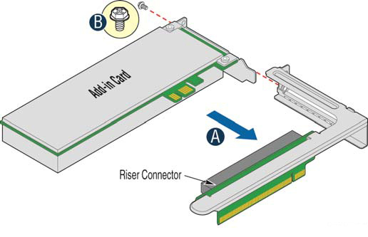
Figure: Installing a PCI Adapter to the Riser Assembly for Slot 1
6. Replace the cover on the chassis.
7. Connect the power cords.
8. Connect the cables.
9. Power up the appliance and check the status lights.
To install a PCIe card in slots 2 and 3
1. Remove the adapter card air duct by lifting it straight up.
Figure: Installing a PCI Adapter to PCI Riser 3 Assembly
3. If you are replacing an existing PCIe card, carefully pull the card from the riser card.
4. Hold the new card between the front bezel and the rear of the card to avoid ESD damage.
Note: Make sure the cards are seated properly in the PCIe enclosure. If they are not seated properly, the cards do not function.
8. Install the adapter card air duct.
Align the hole on the front of the air duct with the alignment pin on the chassis and lower the air duct into place.
9. Replace the cover on the chassis.
10. Connect the power cords.
11. Connect the cables.
12. Power up the appliance and check the status lights.
To test SteelHead NICs
1. Connect to the SteelHead CLI.
For detailed information, see the Riverbed Command-Line Interface Reference Manual.
2. Enter enable mode. At the system prompt, enter the following command:
amnesiac > enable
amnesiac #
3. Verify that the NIC is correctly installed.
For example, to verify the network cards on a SteelHead xx70, at the system prompt enter the following command:
amnesiac # show hardware all
Hardware revision: A
Mainboard: Platform Tarpon 2UAGB Motherboard 2U 2.5 CI, 425-00270-01
Slot 0: .......... 2 Port Copper GigE Gen2 PCIe Non-Bypass Module, Integrated
Slot 1: .......... 4 Port Copper GigE Gen2 PCIe Network Bypass Card, 410-00115-01
Slot 2: .......... 2 Port SR Fiber 10 GigE Gen2 PCIe Redirector Card, 410-00302-03
Note: Run the in-path reset-iface command in configuration mode to reset the main interface and recognize all ports.
Installing Cards in 2U Appliances
This section describes how to install cards in the 2U SteelHead CX and SteelCentral xx70 appliances.
The following figure identifies the PCIe slot locations.
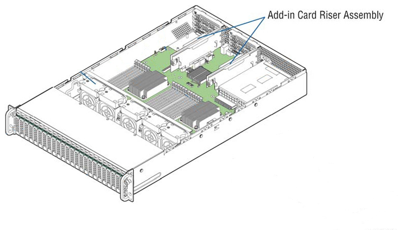
Figure: PCIe Slot Locations for 2U xx70 Appliances
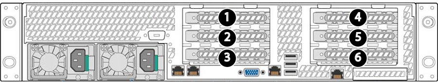
SteelHead CX5070, CX7070, and SteelHead Interceptor 9600 appliances ship with a four-port 1-GbE copper bypass card installed in slot 1. The CX7070H also includes a preinstalled compression card in slot 3. You can use the remaining slots for expansion. The preferred order for populating expansion slots is 2, 3 (if available), 6, 5, and 4. Install the 10-GbE NICs before 1-Gbps NICs when following the preferred slot order.
SteelCentral NetShark network cards must be in slots 1 and 2. (Fill slot 1 first.)
RAID cards must be in slot 4.
Compression cards must be in slot 3.
Due to space limitations, slots 3 and 6 support only half-length cards. (There are no restrictions for height in these slots.)
To prepare to install or replace a network card
1. Power down the appliance.
2. Remove the power-supply cord.
3. Remove the cables connected to the appliance.
4. Remove the appliance from the mounting rack, if necessary.
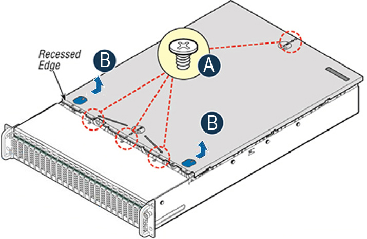
Figure: Removing the Appliance Cover
The riser assemblies are accessible.
Figure: PCI Riser
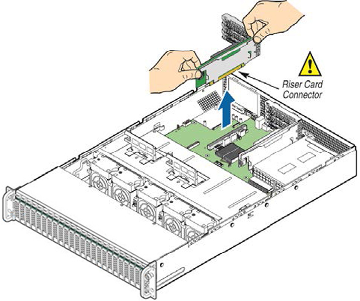
Removing and Installing the Riser Assembly
The PCI riser assembly connects the cards to the appliance. You need to remove the assembly to add or replace a card.
To remove the riser assembly
• Grasp the riser assembly with both hands and pull up to remove from the appliance.
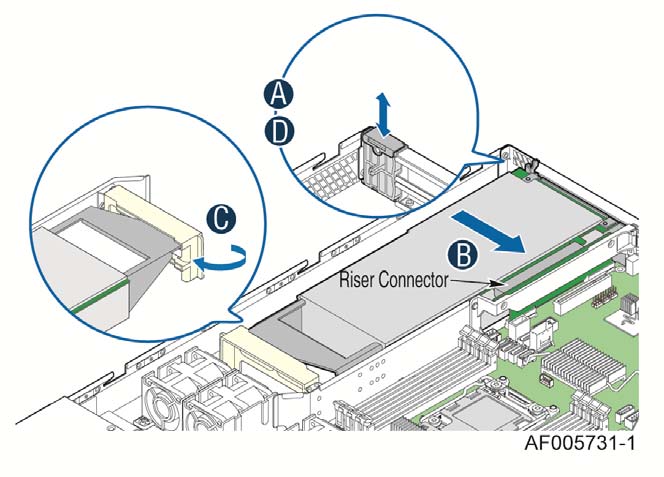
Figure: Removing the PCI Riser Assembly
To install the PCI riser assembly with full-length cards
3. Position the riser card edge connector over the server board riser socket and align the two hooks on the back edge of the riser assembly with the slots on the back of the chassis, and then press straight down into riser socket (see
Figure: Installing the PCI Riser Assembly, letter C).
Figure: Installing the PCI Riser Assembly
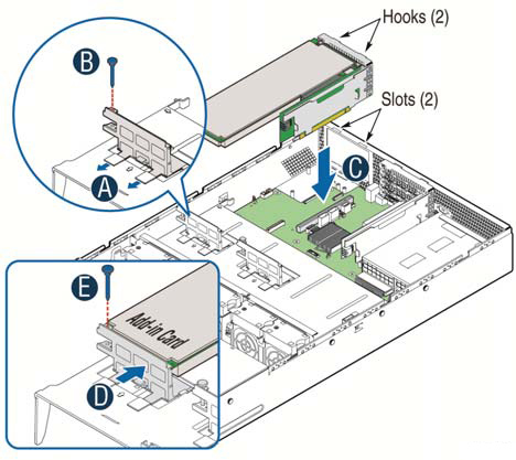
To install the riser assembly without full-length cards
1. Position the riser card edge connector over the server board riser socket.
2. Align the two hooks on the back edge of the riser assembly with the slots on the back of the chassis.
Installing and Removing a PCIe Card
Follow these instructions to install or remove a card from your 2U appliance.
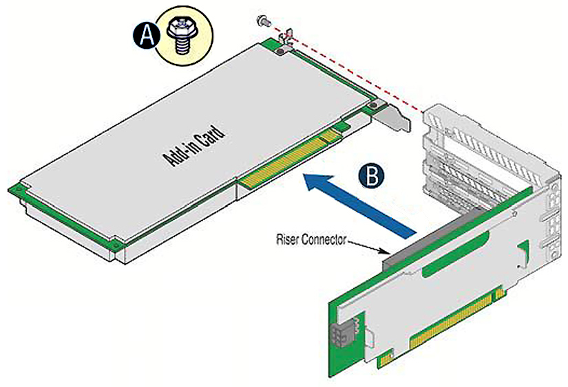
To install a card
1. Remove the riser assembly.
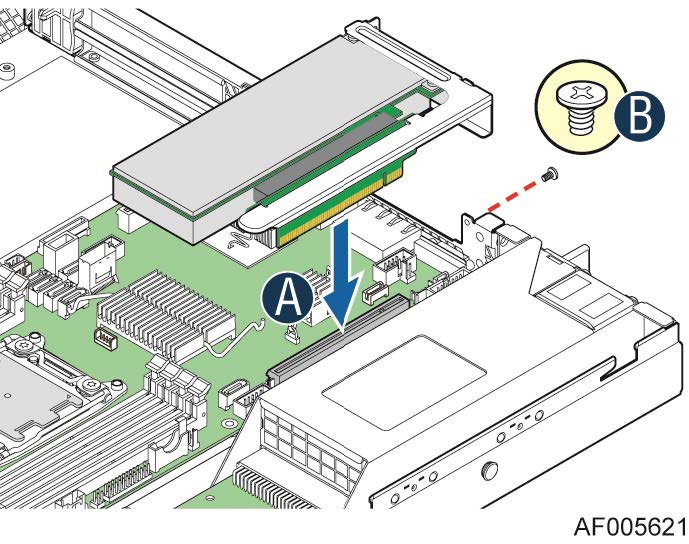
Figure: Installing a PCI Add-In Card
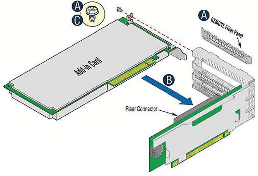
5. Ensure that all empty card slots have filler panels.
6. Replace the riser assembly.
7. Replace the cover on the chassis.
8. Connect the power cords.
9. Connect the cables.
10. Power up the appliance and check the status lights.
To remove a card
1. Remove the riser assembly.
Figure: Removing a PCI Add-In Card
4. Ensure that all empty card slots have filler panels.
5. Replace the riser assembly.
6. Replace the cover on the chassis.
To test SteelHead NICs
1. Connect to the SteelHead CLI.
For detailed information, see the Riverbed Command-Line Interface Reference Manual.
2. Enter enable mode. At the system prompt, enter the following command:
amnesiac > enable
amnesiac #
3. Verify that the NIC is correctly installed.
For example, to verify the NICs on a SteelHead 5070, at the system prompt enter the following command:
amnesiac # show hardware all
Hardware revision: A
Mainboard: Platform Tarpon 2UAGB Motherboard 2U 2.5 CI, 425-00270-01
Slot 0: .......... 2 Port Copper GigE Gen2 PCIe Non-Bypass Module, Integrated
Slot 1: .......... 4 Port Copper GigE Gen2 PCIe Network Bypass Card, 410-00115-01
Slot 2: .......... 2 Port SR Fiber 10 GigE Gen2 PCIe Redirector Card, 410-00302-03
Note: Enter the in-path reset-iface command in configuration mode in the CLI to reset the main interface and recognize all ports.
Identifying Interface Names
The interface names for the NICs in the SteelHead Management Console and the CLI are a combination of the slot number and the port pairs (lan<slot>_<pair>, wan<slot>_<pair>). For example, if a four-port NIC is located in slot 1 of your appliance, the interface names are lan1_0, wan1_0, lan1_1, and wan1_1 respectively.
The interface names for the NICs in the SteelCentral NetExpress and SteelCentral NetProfiler are a combination of the slot number and the port pair (mon<slot>_<pair>).