Path Selection
This chapter describes path selection. Path selection is available in RiOS 8.5 or later. Path selection enables the SteelHead to redirect traffic to a predefined available WAN path for a given application in real-time, based on path availability. This chapter includes the following sections:
Note: To avoid repetitive configuration steps on single SteelHeads, Riverbed strongly recommends that you use the SCC 9.0 or later to configure path selection on your SteelHeads. SCC enables you to configure one time and to send the configuration out to multiple SteelHeads instead of connecting to a SteelHead, performing the configuration, and repeating the same configuration for all SteelHeads in the network.
For more information about path selection, including configuration, see the SteelHead Management Console User’s Guide and the Riverbed Command-Line Interface Reference Manual.
This chapter requires you be familiar with
Topology and
Application Definitions.
Note: If you are using a release previous to RiOS 9.0, the features described in this chapter are not applicable. For information about applications before RiOS 9.0, see earlier versions of the
SteelHead Deployment Guide on the Riverbed Support site at
https://support.riverbed.com.
Overview of Path Selection
Path selection is a RiOS technology commonly known as intelligent dynamic WAN selection. You can use path selection to define a specific WAN gateway for certain traffic flows, overriding the original destined WAN gateway.
WAN egress control is a transparent operation to the client, server, and any networking devices such as routers or switches. When you configure path selection, the SteelHead can alter the next hop gateway transparently for the client traffic. This granular path manipulation enables you to better use and more accurately control traffic flow across multiple WAN circuits.
You must know the following nomenclature prior to reading the information in this chapter:
• Topology - The topology combines a set of parameters that enables a SteelHead to build its view onto the network. The topology consists of network and site definitions, including information about how a site connects to a network. With the concept of a topology, a SteelHead automatically builds paths to remote sites.
For more information about topology IP segment parameters, see
Topology.
• Uplinks - An uplink is a logical medium that connects the site to a WAN network. A site can have a single or multiple uplinks to the same network and can connect to multiple networks. You can use multiple uplinks to the same network for redundancy. Uplinks serve as a logical connection that path selection uses to steer traffic. Local site uplinks are of upmost relevance for path selection.
• Destination site - A destination site provides the IP segment parameter for a path selection rule destined towards a preconfigured remote site destination. The Any parameter selection is a blend of all configured custom sites, and the DefaultSite selection indicates any destination excluding preconfigured custom sites.
• Applications - An application is a set of criteria to classify traffic. The definition of an application enables the SteelHead to ensure that the traffic belonging to this application is treated according how you have configured it. Technically an application definition means that the SteelHead can allocate the necessary bandwidth and priority for an application to ensure its optimal transport through the network. You can define an application on manually configured criteria or by using the AFE, which can recognize more than 1200 applications.
• Relay - Relay is traffic specified by the rule to be subject to path selection internal switching and follows the normal client default gateway (the original path) as intended by the end client or routed LAN.
Path Selection Implementation
This section includes the following topics:
Path Selection Workflow
Path selection configuration is highly dependent on the network, site, and uplink configurations, defined in
Topology. You must complete topology configuration according to your physical network design.
Note: Path selection configuration in RiOS 9.0 and later differs considerably from previous RiOS versions. As such, configuration migration from previous versions is neither compatible nor supported.
To avoid repetitive configuration steps on single SteelHeads, Riverbed strongly recommends that you use the SCC 9.0 or later to configure path selection on your SteelHeads. SCC enables you to configure one time and to send the configuration out to multiple SteelHeads instead of connecting to a SteelHead, performing the configuration, and repeating the same configuration for all SteelHeads in the network.
To configure path selection, you must complete the following tasks:
1. Configure the multiple different WAN networks in the environment on the Networking > Topology > Sites & Networks page. Even though this configuration is not required, Riverbed recommends that you complete this step to simplify the configuration.
The network topology configuration is more of a concept to bind different SteelHeads over a common logical connection. Path selection is typically deployed with WAN designs composed of two or more different circuits; each one of those circuits provides a distinct path to be used by path selection (example shown in
Figure: Example Network Topology). There are three distinct circuits: MPLS, VPN, and internet.
Figure: Example Network Topology
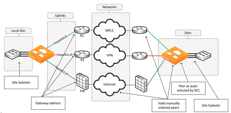
Figure: WAN Networks

Figure: Site Configuration
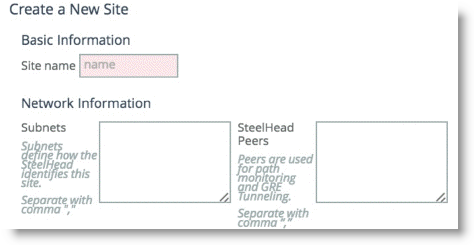
The Sites configuration is integral for the path selection feature. You must create any remote destination site you want to build a path to. Path selection takes into account the remote destination IP subnets that you configure as a parameter for the site. The IP subnet property is how a SteelHead is able to direct traffic towards a specific destination site because it can identify the destination IP address in the packet header.
A site configuration contains the SteelHead peers field property. SteelHead peers are distinct IP addresses you choose to poll, in order, to verify path availability. Riverbed highly recommends that you use the remote SteelHead in-path IP address as a peer address when possible; for example, a remote peer SteelHead in-path IP is required for the firewall traversal GRE feature. You can enter additional addresses that are probed for path availability status. Each entered IP address is attempted as a separate independent path.
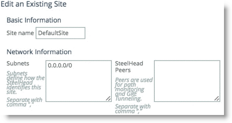
As part of the site configuration, a default site is preconfigured by default. You need the default site because it serves to catch traffic that is not part of any preconfigured sites: for example, internet-bound traffic. Depending on this traffic flow pattern, you must enter a value in the SteelHead Peer field. Riverbed generally recommends that you edit the existing default site (
Figure: Existing Default Site) to use:
• the data center SteelHead IP address for internet-bound traffic that is backhauled through the data center.
• the local router gateway when the internet-bound traffic is exiting directly out of the branch.
Figure: Existing Default Site
3. Edit the existing local site to configure it for your design.
A local site is always created by default and cannot be deleted. However, you can rename the local site to reflect your network design.
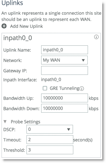
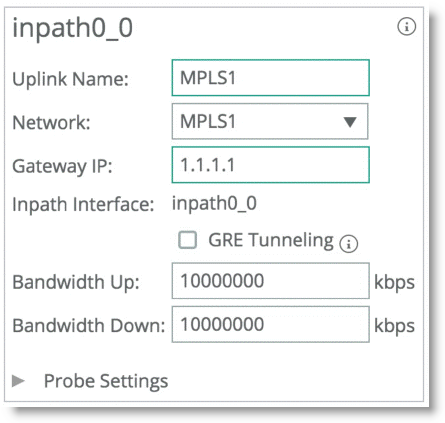
The uplinks configuration is integral to configuring the local site. Uplinks dictate the egress path out of the SteelHead and hence are critical to the path selection configuration. You can rename uplinks to a more meaningful description, and you can tie them to a network that you have already defined.
The uplink name is recalled in the path selection page as a selection to direct traffic. Uplinks, which are configured by default, are hard tied to each in-path interface available to the SteelHead. Local site uplinks require that you configure a gateway IP address. By default, the gateway IP address is identical to the already configured in-path gateway IP address, but it is configurable if you want to change it. Riverbed recommends that you point the uplink gateway to the WAN-facing IP address in case the in-path gateway is configured towards the LAN.
The gateway IP address is a WAN-side IP address of the next hop device you want to direct the traffic to. You do not need to configure remote site uplinks for path selection. The GRE tunneling option is enabled for certain designs that require tunneling.
In RiOS 9.0 and later, the SteelHead automatically probes through each uplink you configure at the local site. This probe is the mechanism by which the SteelHead automatically configures the path that is available. The SteelHead probes from each uplink towards each configured remote site that you configure in the Peer SteelHead IP address field parameter.
RiOS 9.2 introduces the optional values to the probe settings:
– Probe backoff - Sets an upper limit to the frequency of the probing in the absence of traffic on the network. This limit is beneficial in a hub-and-spoke networks in which spoke-to-spoke communication is not frequent; therefore, unnecessary probing is greatly reduced. On the SteelHead, you can change the value using the following CLI command:
topology network <name> probe_backoff <seconds>
where <name> is the network you want to administer, and <seconds> is the numeric value in seconds.
– Probe bandwidth - Sets an upper bandwidth limit to the probes, which are being generated by a specific uplink. This option helps to control the amount of traffic used by probing. This feature is beneficial on small links on which you want to exercise more control on the link. On the SteelHead, you can change the value using the following CLI command:
topology site {<site-name> | local | default-site} uplink <uplink-name> network <name> bandwidth_up <kbps> bandwidth_down <kbps> [gateway <ip-address>] [probing_bw <kbps>]
where <site-name> is the site name, <uplink-name> is a specific uplink, and <kbps> is the bandwidth limit amount of the probing you configure in kilobits.
For more information, see the SteelCentral Controller for SteelHead Deployment Guide.
Figure: Example Uplink Configuration
Path selection is a global function that influences all traffic traversing the SteelHead. You cannot configure path selection to only intercept traffic on certain LAN interfaces. Path selection is unlike QoS traffic enforcement in which you can select the desired interfaces to enforce traffic shaping. In RiOS 9.0 and later, path selection introduces the concept of site identification. For example, if you want to identify a certain application that is destined to a certain site, you can elect to take an action on the exit paths.
For example,
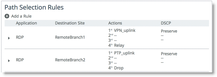
Figure: Path Selection Rules shows an applications named RDP. Depending on the original destination, the traffic can follow two different uplinks. If you want to send the RDP traffic towards remotebranch1, then the traffic is steered towards the VPN path. On the other hand, if you want the traffic to travel to RemoteBranch2, then the traffic is steered to the PTP uplink. If the PTP path is not available, then traffic is configured to be dropped.
Figure: Path Selection Rules
RiOS 9.0 and later include the following destination concepts:
• Default Site - The Default Site contains the IP subnet property of the default site configured in the Topology section. For destination identification, the IP subnet property matches the 0.0.0.0/0 setting. You select the default-site as the destination for connections typically oriented towards unknown areas, such as internet-bound destinations.
• Any - The Any setting combines identifications of all known configured sites, including the Default-Site. Rather than configuring a separate identical path selection rule for every known site, choose the Any setting to match the destination address of every configured site. This setting ensures that the application configured, and any matching configured site or the default-site are steered onto the selected uplink. The Any destination concept is important to understand. The concept serves as a mean to reduce the configuration steps required, yet provide a common application steering design.
These settings are available when you add a rule on the Networking > Network Services: Path Selection page.
Note the order of the path selection rules in relation to the applications they refer to and how the site definitions come into play. As RiOS 9.0 introduces application groupings, certain configurations can consist of a path selection rule that you configure for a specific single application followed by another application group rule, which includes the previous application.
In the case of overlapping application, the order of the rule is the deciding factor as far as which rule is enacted for the path selection logic. In relation to the sites concept, RiOS identifies and selects the rule with the longest site prefix match first. Therefore, a rule specific for a site takes effect before the Any rule.
Example of a Path Selection Implementation
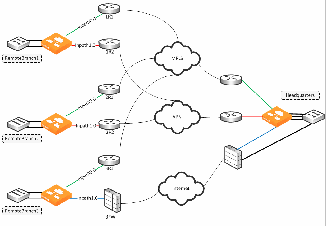
Figure: Path Selection Design Example shows an example of a WAN design in which path selection is implemented. The example shows multiple dual-homed sites with an MPLS WAN link provided by a carrier, labeled MPLS, and the second link is private VPN circuit. A third site, Remote Branch3, has a single connection back to the MPLS cloud and a secondary link through an internet-based firewall. All traffic, including public internet, is backhauled through the main headquarters site and egresses directly through the firewall connection.
Figure: Path Selection Design Example
Each path is probed for availability based on the probe-setting schedule with default configuration of 2 seconds. The probe transmits an ICMP request from the configured in-path interface toward the probe destination IP, and after receipt of an ICMP response, the path is declared available for use. A path is determined down after the count of consecutive probe failures surpasses the configured probe threshold. The default threshold is three probe packets.
The SteelHead is looking for an ICMP response from the probe destination to determine path availability. Even if the ICMP response traverses unintended devices or WANs, the path is available as long as the configured in-path interface receives the ICMP response. This behavior can result in false positive path availability. The example shown in
Figure: Path Selection Design Example assumes that the MPLS path is configured with inpath0_0, along with a probe destination of 2R1. Even if the MPLS network fails, the path remains up as long as 2R1 continues to send ICMP responses to the SteelHead inpath0_0. Likewise, assume that the MPLS path, inpath0_0, is configured to send probes to 3R1 as the probe destination.
Given the bad scenario, in which the MPLS fails, 1R1 forwards the ICMP request to 2R1, across the VPN, through 3FW, and on to 3R1. 3R1 can respond, sending ICMP responses down and back over the VPN, reaching the SteelHead inpath0_0. In either case, the MPLS path availability remains connected, though the likely intention is that the path shows it is not connected when the MPLS WAN is down.
Riverbed recommends that you locate an address on the remote side of the path, and make sure devices in the path treat the probe as expected during a failure. This connection is best verified by conducting traceroute operations to verify the path flow traversal during outages. If the MPLS path has inpath0_0 configured with a probe destination of R31 and a next-hop gateway of 1R1, then configure 1R1 in which traffic to 3R1 can only go over the MPLS network. If the MPLS network fails, then configure 1R1, or another device, to drop the ICMP request probe from inpath0_0 to 3R1. An appropriate probe destination for a path can be a remote router loopback address or one of the remote SteelHead in-path interfaces.
In RiOS 8.6 and later, you can configure the SteelHead on a per-uplink basis to perform firewall traversal using GRE encapsulation to a remote SteelHead peer. The SteelHeads use the configured destination IP for the probe as the other endpoint when you set the tunnel mode setting in a path to GRE. Remote side GRE tunneling will require to be configured as well, with similar Path Selection rules, if you intend to maintain traffic symmetry.
Each path has its own independent IP address to probe, yet this address can be the identical one for each path. Therefore, each path can poll on the same probe destination. The ICMP request has to use whichever physical interface is selected for the path. In
Figure: Path Selection Design Example, the MPLS path egresses its packets using the inpath0_0 interface, hence all traffic uses the corresponding WAN0_0 interface. Meanwhile, the VPN path egresses its packing using in-path0_1, hence all traffic uses the corresponding WAN0_1 interface.
The next-hop gateway serves the following purposes for the path selection design because the gateway provides the new routing path for packets to travel through to their destination:
• Replaces the destination MAC address of packets with the MAC address of the alternate gateway. The gateway MAC address is learned by the SteelHead in-path interface. As part of steering packets, the destination MAC address of the packets is altered to match learned MAC address of the configured new next-hop gateway.
Path selection requires a Layer-2 connection between the SteelHead and the gateway; the connection between the SteelHead and the next-hop gateway cannot be a routed link. This action is referred to as Layer-2 redirect by next hop MAC.
• Switches the outbound interface from the original in-path interface to the desired primary path.
The path selection solution is implemented completely transparently, regardless of existing routing metrics. The primary path selection path gateway accepts the steered packets and proceeds to forward them onto the corresponding WAN.
• The SteelHead takes no action in having to reconfigure the Layer-3 routing parameters of the routers in the network.
The SteelHead never takes an action to inject any routes or alter the routing instances. The traffic source whose packets are sent to the primary path selection gateway have no visibility into the changes the SteelHead applies. Therefore, the client (or server) continues to send any and all packets to the gateway address they are configured with. This action is referred to as Layer-2 redirect by interface.
WAN interface selection is based on identified traffic type and availability of the end-to-end path, depending on how you configure your SteelHead. Path selection remains functional even if you pause the optimization service or if the optimization service becomes unavailable. If the SteelHead fails completely, then path selection is no longer applicable and traffic proceeds as normal, following its default gateway.
Identifying Traffic Flow Candidates
The critical step for path selection is to identify traffic flow and to associate these traffic flow candidates with a different, configured uplink. In this step, the AFE interacts with the path selection feature. Use the following methods to identify traffic that can benefit from path selection:
• The AFE can help you to identify the traffic and steer the traffic along a configured path. For more information about AFE, see
Application Flow Engine.
Some limitations exist when you use AFE in conjunction with path selection. AFE, or any deep packet inspection technique, requires examining several of the beginning packets of a connection before it can identify the traffic. That means that after the beginning packets have been identified, they can be sent on a path different than the one you chose. This midstream switching has implications in various environments involving firewalls and dual internet egress environments. For more details, see
Firewall Path Traversal Deployment and
Design Considerations.
• You can also use IP header information as an alternate method for identifying traffic. IP header information identification consists of any of the following combinations:
– Source IP
– Destination IP
– Source port address
– Destination port address
– DSCP mark
– VLAN tag
– Optimized/Unoptimized traffic
– Layer-4 protocols (TCP, UDP, GRE, and so on)
For each path selection rule you configure, you can add a maximum of three different uplinks. The uplinks you choose cascade from one to the next, based on availability. RiOS 9.0 and later include the concept of application groups and enables you to reference multiple application types using a single path selection rule designating this application group.
In the brief duration when classification of traffic is not yet completed, traffic is treated according to a matching header-based rule or the site default rule. This period of time could have implications during path failure when such a rule does not specify the uplink preference and sent down the original path. In this case, new connections, or connections on which application identification is yet to complete, might never become established. Riverbed recommends that you specify an uplink preference for all path selection rules, both application and header-based rules, as well as specify the uplink preference for the site default rule.
You have the option to drop the traffic if no alternate path is available. Dropping traffic is useful when you prefer not to use bandwidth on an available path in case of failure on the primary selected path. If you choose not to override the original intended route, then traffic is relayed normally. The traffic continues to flow normally along the original intended path, following the default gateway.
Traffic identification and path steering is independent of optimized versus pass-through traffic. Path selection takes action on the configured traffic, no matter the optimization status of the traffic.
Path selection configuration is also independent of any QoS settings; this means that you can apply path selection rules with and without enabling QoS marking or shaping or both. Path selection uses its own independent rule sets apart from QoS; therefore, it does not increase the rule count number against the model limit as specified for QoS.
Remember that return traffic in path selection is not influenced or manipulated in any way to take the steered path from the sending SteelHead. You must install and configure a remote SteelHead with the appropriate path selection configuration, and steer the return traffic on the same path.
Configuring Path Selection
This section describes the basic steps for configuring path selection using the SteelHead Management Console. This section also includes a configuration example. For more information about the Management Console, see the SteelHead Management Console User’s Guide.
You can also use the Riverbed CLI to configure path selection. For more information about path selection commands, see the Riverbed Command-Line Interface Reference Manual.
Riverbed strongly recommends that you use the SCC 9.0 or later to configure path selection on your SteelHeads. SCC enables you to configure one time and to send the configuration out to multiple SteelHeads instead of connecting to a SteelHead, performing the configuration, and repeating the same configuration for all SteelHeads in the network. For details, see the SteelCentral Controller for SteelHead User’s Guide.
To perform the basic steps to configure path selection
1. Configure the topology as described in
Topology.
• Configure the uplinks for the local site and define the proper gateway IP address and peer IP address.
• Configure remote sites and define the associated subnets.
You do not need to configure uplinks for the remote and default site.
2. Choose Network > Network Services: Path Selection and select Enable Path Selection.
3. Click Save.
Figure: Add a New Path Page
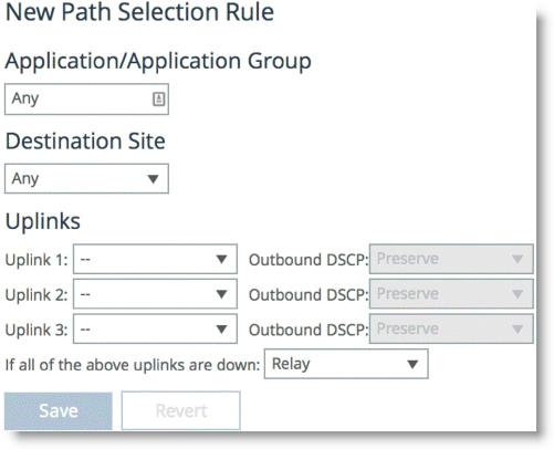
5. Specify the name of the application or application group name.
6. Select the destination.
7. Specify a preconfigured uplink to carry the traffic.
8. Change the DSCP mark per uplink path (optional).
9. Click Save.
You do not need to restart the SteelHead to enable path selection. At this point, path selection is enabled and you have configured the different available paths.
Valid Path Selection Deployment Design Examples
This section shows valid path selection deployment examples. The examples in this section show only one side of the WAN. You must assume that the remote side also has similar path selection capabilities and configurations for symmetric for return traffic. This section includes the following topics:
Basic Multiple Route Path Deployment
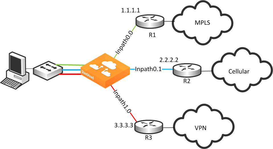
Figure: Basic Multiple Route Path Deployment shows a SteelHead connected to three separate routers on three distinct in-path connections. Inpath0_0 is connected to Router 1, which is serving an MPLS connection. Inpath0_1 is connected to Router 2, which is serving a cellular-based WAN connection. Inpath1_0 is connected to Router 3, which is serving a VPN-based connection.
Figure: Basic Multiple Route Path Deployment
1. From the Management Console, choose Networking > Topology: Sites & Networks.
2. Select Add a Network and create a separate network for each of the three different carriers, labeling each path with the proper name as shown in
Figure: Three Path Selection Networks.
Figure: Three Path Selection Networks

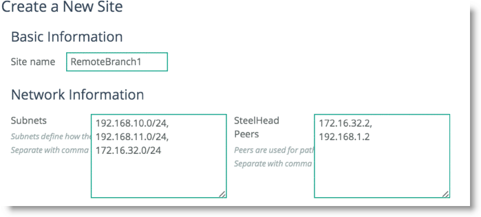
3. Scroll down and select Add a Site (
Figure: Add a New Site). The Subnets field is composed of the local subnets situated on the LAN side of the SteelHead. The SteelHead Peers field is a collection of remote IP addresses you want to probe to validate the path status.
Figure: Add a New Site
4. Repeat
Step 3 for all remote sites in the path selection design.
To configure remote sites, you are required to enter the remote site name, IP segments residing at that remote site, and peer IP addresses to probe to determine path availability.
5. Click
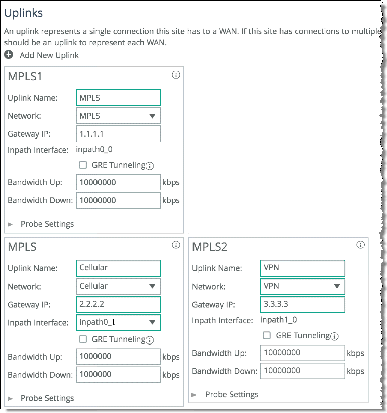
Edit Site for the Local site, change the site name, and properly assign the Network label according to the proper in-path interface as shown in
Figure: Editing the Local Site.
Figure: Editing the Local Site
6. Click Save.
7. Choose Networking > Network Services: Path Selection.
8. Select Enable Path Selection and click Save.
9. Scroll down and select Add a Rule.
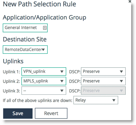
10. Configure the application with the desired path order.
Select the specific application or entire Application Group. Next, select the destination site, and choose the uplink interface in order of preference.
Figure: Configuring Path Selection for Application General Internet
Complex Parallel Path Deployment
Figure: Complex Parallel Path Deployment shows a dual parallel SteelHead deployment on the WAN side with a four-way HSRP design. On the WAN side, Router 1 and 2 connect to the MPLS1 provider, and Router 3 and 4 connect to the MPLS2 provider. On the LAN side, each switch has a connection to both providers through a separate router.
Figure: Complex Parallel Path Deployment
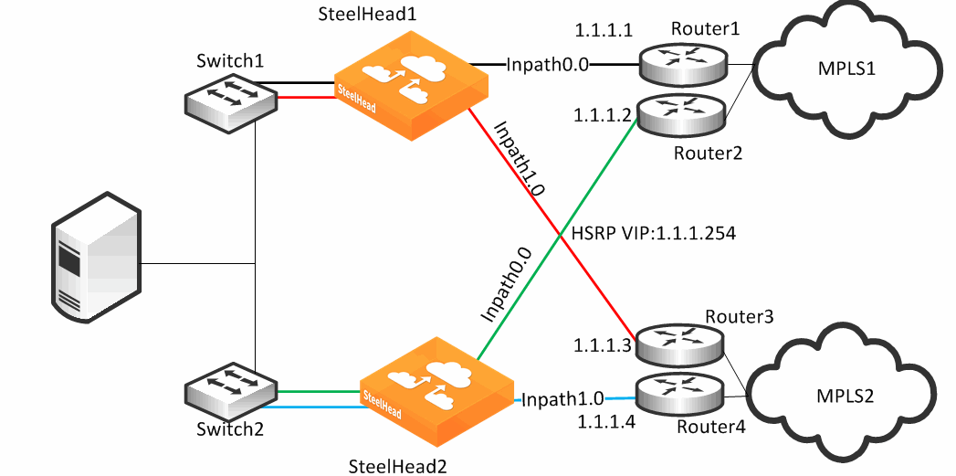
While each of the links in
Figure: Complex Parallel Path Deployment can also be individual Layer-3 links, in this example there are two networks with HSRP configured on each network. When you define uplinks, use the real IP addresses of the routers as the gateway, not the virtual IP address. If you use a virtual IP address, you can cause the gateway to reside on the LAN side of the SteelHead in-path interface, resulting in unintended traffic flow. If your design is configured with a single HSRP group covering both routers, you must use the real IP address of the router as the gateway, not the virtual IP address.
Each SteelHead is connected to each router with the MPLS provider; therefore, both SteelHeads can make uniform path selection decisions, with traffic moving toward the same router and provider.
Riverbed recommends that you configure both SteelHeads with equivalent paths, uniform path selection rules and logic.
Figure: Complex Parallel Path Deployment shows SteelHead configured with two networks: MPLS1 and MPLS2.
Figure: SteelHead1 Network Topology Configuration

Figure: SteelHead1 Uplink Configuration shows SteelHead1 uplink configuration.
Figure: SteelHead1 Uplink Configuration
SteelHead2 is configured with the equivalent paths, but with the respective gateway of Router2 IP address 1.1.1.2 and Router4 IP address 1.1.1.4.
If your design includes a single HSRP group covering both routers, configure SteelHead2 so that it is identical to that shown in
Figure: SteelHead1 Uplink Configuration, in which the path gateway references the real IP interface and not the virtual IP.
Complex Single In-Path Interface Deployment
Figure: Complex Single In-Path Interface Deployment shows the SteelHead connected through a single in-path interface connection, but the WAN side is composed of multiple WAN routers, each to their own separate provider. The LAN side of the routers all share the same IP segment. Because they share the same IP segment, achieving path selection configuration in this setup is valid, because the SteelHead can be configured with different gateway addresses traversing the same in-path interface. You must configure a router gateway redundancy mechanism, such as HSRP or VRRP. This configuration needs a redundancy mechanism, because the SteelHead does not act as the default gateway for the clients.
The redundancy mechanism is completed using multiple uplinks for a single in-path.
Figure: Complex Single In-Path Interface Deployment
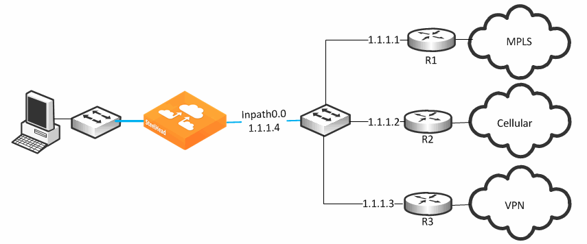
Figure: SteelHead1 Network Topology Configuration

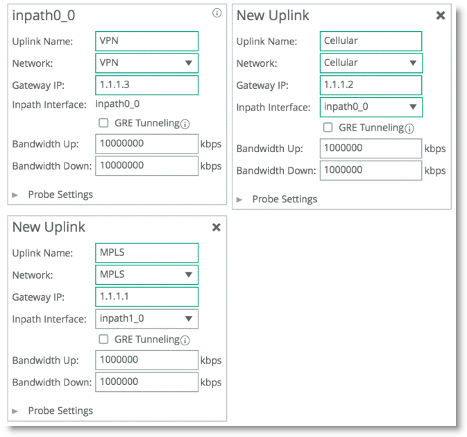
Figure: Uplink Configuration represents the uplink configuration for the deployment shown in
Figure: Complex Single In-Path Interface Deployment. The Local Site uplink configuration reflects additional uplinks each associated with a separate network in which each uplink shares the same inpath0_0 as the egress interface, but the gateway IP differs for each network desired.
Figure: Uplink Configuration
Note: A complex single in-path interface deployment is valid for path selection when all the routers are on the same subnet as the SteelHead single in-path interface. If the in-path interface is on an 802.1Q trunk, you cannot use path selection to direct traffic to different routers on different VLANs. The switch shown in
Figure: Complex Single In-Path Interface Deployment is a Layer-2 switch; therefore, path selection can make the decision to send traffic to the appropriate router MAC address.
Serial Deployment
Figure: Serial Deployment shows a dual serial SteelHead deployment. SteelHead 1 is the client SteelHead, and SteelHead 2 is referred to as the
middle file engine (MFE). On the WAN, Router 1 is connected to the MPLS provider, and Router 2 connects to the customer internal network using a VPN connection. In this example, Riverbed recommends that you use the real IP address of the router as the path gateway instead of the virtual IP provided by HSRP and VRRP.
Figure: Serial Deployment
You can use path selection in a serial deployment if:
• SteelHeads have identical path selection configuration.
• correct addressing is in use. You must configure SteelHead2 to relay the inner channel of SteelHead1.
• you are using Full Transparency. You must use the path-selection settings bypass non-local-trpy enable command on SteelHead2.
Firewall Path Traversal Deployment
This section describes how to configure firewall path traversal deployment. This section contains the following topics:
Stateful firewall devices typically provide security services including:
• tracking the TCP connection state.
• blocking a sequence of packets.
Stateful security devices add a level of complexity to path selection environments when the SteelHead attempts to make any path changes to a connection midstream. The most common examples of midstream switching are:
• failure of a higher-priority path, failing to firewall path.
• recovery of path, resuming traffic to a firewall path.
• using AFE for identification because the first packets of a connection are not recognized yet and can traverse a default path.
When a path changes midstream, the stateful firewall device is likely to see only some or none of the packets necessary to keep state and sequence numbers. When receiving packets are perceived to be out of order or belonging to a connection with inaccurate state information, stateful firewalls generally drop these packets.
Beginning with RiOS 8.6, Riverbed recommends that you use the firewall path traversal capability to leverage GRE tunneling over paths traversing a stateful firewall. When you use standard GRE between SteelHeads, connections can be switched midstream because the firewall only detects the encapsulated packets. You can configure GRE tunneling per uplink, and when enabled, the SteelHead attempts to encapsulate packets to the remote SteelHead at the configured remote peer IP address. The peer IP address needs to be an in-path IP address of a remote SteelHead. You can use multiple uplinks using GRE tunneling between the same SteelHeads, and the original packet or QoS-configured DSCP values are reflected in the GRE packets.
Note: There is a loss of visibility on the firewall when you use GRE encapsulation. You also might need additional configuration on the firewall to allow the GRE packets between SteelHeads.
MTU and MSS Adjustment When Using Firewall Path Traversal
When you use GRE tunneling, consider that there is an additional 24-byte overhead added to packets. This overhead can cause fragmentation of large packets, because the extra added bytes cause the packet to exceed the maximum transmission unit (MTU) configured in the network. Fragmentation has the negative effect of sending inefficiently sized packets and dropping packets that might have the do not fragment option set.
You can prevent fragmentation by adjusting the maximum TCP payload, or MSS value, to account for the overhead added by GRE. When you configure a path with the tunnel mode set to GRE, the SteelHead measures to reduce potential fragmentation for TCP traffic.
This automatically applied MSS value ensures that in most environments TCP packets are not fragmented, even with the additional GRE overhead. In an optimized case, the client and server connections with the SteelHead are not impacted by the MSS adjustment procedure. For pass-through TCP traffic, the SteelHead adjust the MSS value to make room for a GRE header. To turn off this automatic MSS adjustment, use the no path-selection settings tunnel adjust-mss enable command.
For more information about MTU, see
MTU Sizing.
Firewall Path Traversal Deployment Example
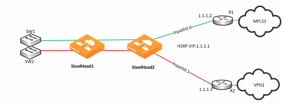
Figure: Firewall Path Deployment shows a dual-parallel installation of SteelHeads in a dual-homed WAN scenario. In this example, a firewall is installed on the edge of the internet path. The SteelHead has visibility into both MPLS and VPN paths.
Figure: Firewall Path Deployment
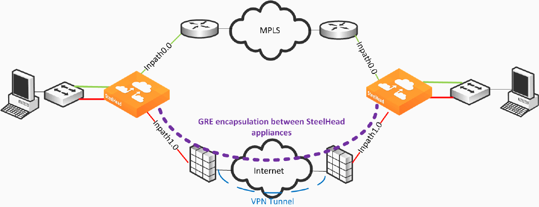
Figure: Firewall Path Deployment defines two uplinks: the green uplink over MPLS and the red uplink traversing stateful firewall devices. The firewall path is configured for GRE tunneling between the SteelHeads. When you configure a path for GRE encapsulation, it affects only the decision of the local SteelHead in that the opposing SteelHead must also have similar path configuration for return traffic to be encapsulated.
The SteelHeads are not providing the VPN functionality over the internet but sending traffic over the VPN tunnel provided by the existing firewalls in the path. Remember that this SteelHead configuration for path traversal over firewalls uses standard GRE encapsulation, which is not a secure method of traversing the internet.
In addition, the firewalls provide other necessary functions, such as NAT, and Riverbed does not recommend that you to use the SteelHead GRE capability instead of direct VPN functionality.
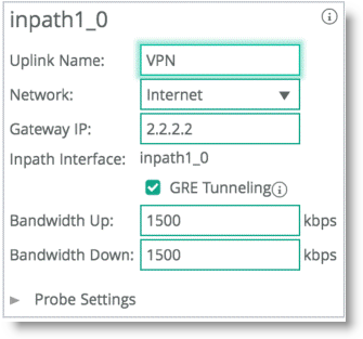
GRE tunneling configuration is enabled during the uplink setup (
Figure: GRE Tunneling). You must denote the remote SteelHead in-path IP address in the peer setup field in order to terminate the GRE tunnel.
Figure: GRE Tunneling
Path Selection and Virtual In-Path Deployment
Riverbed recommends that you not use virtual in-path deployments for path selection, but always use physical in-path deployments. Virtual in-path deployments often have caveats that limit path selection effectiveness, including but not limited to the following:
• Typically, only traffic that is optimized is redirected to the SteelHead; therefore, the SteelHead is limited to identifying and acting on only that subset of total traffic. Although you can configure devices to redirect all traffic, this configuration is often undesirable due to adding increased load and complexity.
• Additional routing devices often exist after the SteelHead makes the path selection decision.
For example, consider an environment with dual Layer-3 switches and dual routers connected to different service providers. Policy-based routing (PBR) is configured on the Layer-3 switches, and the SteelHeads make the path selection decision about which Layer-3 switch to send traffic to. The Layer-3 switches then make an independent routing decision to send traffic to a router, and therefore provider, rendering the SteelHead path selection decision meaningless.
Considering additional routing devices is important in physical in-path deployments, but holds additional weight in virtual in-path deployments because of the added restriction of only certain devices being capable of redirection. For example, many firewall devices have limited functionality when supporting virtual in-path mechanisms.
• Path selection next-hop functionality is not supported with WCCP. The SteelHead cannot choose to redirect packets using a different in-path interface or to send traffic to a configured gateway. Only limited functionality is available, enabling the SteelHead to mark packets with DCSP with different criteria depending on path availability.
Design Validation
In RiOS 9.0 and later you can use CLI commands and SteelHead Management Console report pages to verify path selection operations and to validate your path selection configuration.
For details, see the Riverbed Command-Line Interface Reference Manual and the SteelHead Management Console User’s Guide.
You can use the show commands to verify path selection settings and configuration:
CFE # show path-selection ?
channels Display channel states
interface Name of the interface
rules Display configured path-selection rules
settings Path Selection settings
status Display feature status
CFE # show topology uplinks path-selection stats

show topology uplink <uplinkname> site <Site name> path-selection state

You can validate your design from the SteelHead Management Console with these reports:
Figure: Current Connections Report
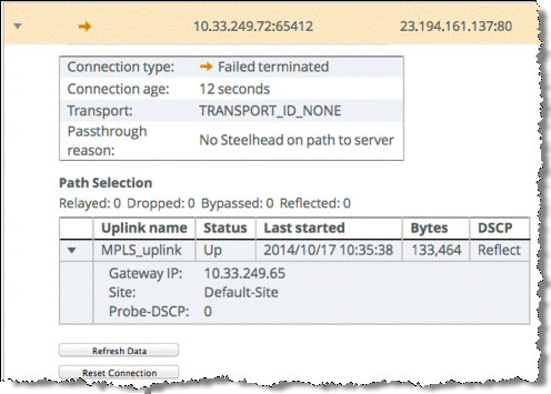
Figure: Path Selection Report

Design Considerations
Consider the following guidelines when you use path selection:
• Path selection does not require dual-ended SteelHead deployments, but Riverbed highly recommends that you maintain return-traffic symmetry.
• You cannot use AFE for internet-bound applications to select paths with different internet egress points. Using AFE implies that packets prior to identification traverse one path, but that after identification, the connection can switch midstream to a different path. If these two paths use different egress points to the internet, the packets on each path use different NAT public internet IP addresses and appear as two different sources to the internet server. Multiple internet egress can exist in these scenarios:
– Direct-to-internet at the branch office and internet at the data center - You cannot use AFE to decide that some internet applications exit directly from the branch office and others from the data center.
For example, the default path that directly reaches the internet is at the branch, but you configure AFE for Facebook traffic to traverse a path to the data center. The beginning packets of the connection exit from the branch with a externally translated address from the branch internet provider. After identified, path selection switches midstream to the path to the data center, where the traffic is translated to a different internet address.
– Dual data centers, each with internet egress - You cannot use AFE to determine what path internet-bound applications traverse.
• Be mindful of WAN-side routing, because it always takes precedence over path selection. Routers on the WAN side of a SteelHead can always override and reroute traffic according to their configuration. Be aware of upstream router configuration, so you that avoid unintended traffic redirection. Placing the SteelHead closer to the edge of a WAN helps to avoid this scenario. Some examples of this scenario include but are not limited to:
– WAN-aggregation layer - All routers consolidate into a pair of Layer-3 switches. Path selection must occur on the WAN side of this layer. This configuration is more common in data centers.
– WAN-side router with multiple circuits - The router decides on which circuit to send traffic. You cannot use path selection effectively in this scenario.
• Transit networks - Transit site traffic is defined as traffic that is not sourced or destined locally. In a topology where some of the sites do not have SteelHeads, behavior can occur where path selection rules are applied asymmetrically, which can lead to asymmetrical GRE-encapsulated traffic. This behavior can cause issues with firewalls such as dropped connections.
To push general path selection rules but selectively turn off path selection for transit site traffic, enter this command:
path-selection-transit-bypass enable
When this command is enabled and transit traffic is bypassed, no path selection matching of rules is applied to transit traffic, which results in traffic being relayed with no failover. Path selection rules are applied to local site traffic even if this command is enabled.
For details, see the Riverbed Command-Line Interface Reference Manual.
• Path selection is not effective in any environment in which independent routing decisions are made at the site after the SteelHead path selection decision has already occurred.
• Subnet side rules exclude subnets from changing paths.
• The SteelHead does not apply path selection configuration for traffic destined onto the same IP segment as the in-path interface. This is useful for routing updates if you have deployed the SteelHead in the direct path of that traffic.
• The SteelHead never takes on the role of the router or of a default gateway. Because the path selection solution is transparent, you do not have to make network design changes to accommodate path selection design.
• The primary and auxiliary interfaces of a SteelHead do not support path selection.
• Path selection is compatible with all virtual and physical SteelHead models running RiOS 8.5 or later.
• You must disable RSP to enable path selection. Current virtualization capabilities, including VSP on SteelHead EX 2.0 and later, are compatible with path selection.
• A SteelHead with path selection enabled has no enforcement on the return path.
If you want to influence the return path of traffic and override the original traffic path, you must deploy a SteelHead near the return traffic WAN junction point. Traffic returning on a different path is commonly known as asymmetric routing. Typically, networks are not designed in this way; however, if this traffic pattern exists, it might not be completely detrimental, because the SteelHead can rely on existing features and complete the optimization.
For more information about asymmetric routing, see the SteelHead Management Console User’s Guide.
• A single SteelHead can maintain optimization even if traffic is received on a different in-path interface from the original sending in-path interface. Because the SteelHead shares internal flow table with itself, it can complete the optimization process with no asymmetric alarm generation.
The following are not supported by path selection:
• Packet-mode optimization
• IPv6 optimization
• WCCP designs with Layer-2 redirection
• Designs requiring specific LAN-side redirection
• Layer-2 WAN
• Single-ended SCPS connections
• Maintaining VLAN transparency
For example, network designs in which the in-path interface is sitting on a VLAN trunk connection and you want to switch a flow onto another VLAN, results in discarded packets, because the VLAN ID field is not reflected upon steering.
Path Selection using GRE encapsulation has the following additional restrictions:
• Virtual in-path deployment is not supported.
• Inbound QoS is not applicable to inner or encapsulated incoming traffic.
• Simplified routing does not learn from tunneled packets. If the default gateway is pointed to the WAN, make sure that you have configured the proper static routes for networks that reside in the LAN.
• Flow export or reports reliant on flow show GRE traffic on the WAN interface. Visibility tools that coalesce or stitch LAN and WAN flows together can be affected adversely.
• The downstream SteelHeads in serial deployments cannot intercept and take over new TCP connections when an upstream SteelHead sends GRE traffic. Even in the event of admission control, a SteelHead continues to perform path selection and tunneling, preventing proper connection spillover to a downstream SteelHead.


