Replacing SteelConnect SDI-2030 and SDI-5030 Gateway Components
This chapter describes how to replace components in the SteelConnect SDI-2030 and SDI-5030 gateways. It includes the following sections:
Field-replaceable units
The SteelConnect SDI-2030 and SDI-5030 gateways contains field-replaceable units (FRUs) that you or a certified service technician can troubleshoot, remove from the gateway, and replace without having to send the gateway to a repair facility.
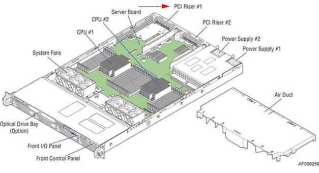
SDI-2030 and SDI-5030 gateway components
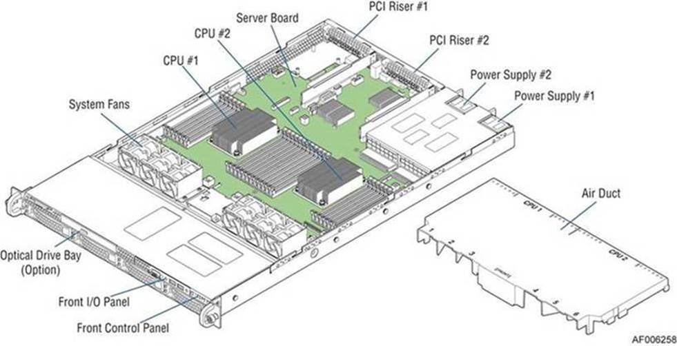
Perform troubleshooting or repairs only as directed in the product documentation or by the online or telephone service and support team. All other servicing should be performed by a certified service technician only. Your warranty does not cover damage due to servicing that is not authorized by Riverbed. Read and follow the safety instructions in the Safety and Compliance Guide.
Required tools
You need the following tools and equipment to replace gateway components:
•An antistatic strap. When you replace gateway components, you must wear a grounded ESD antistatic strap to protect the hardware against electrostatic discharge. Make sure that the strap makes skin contact prior to handling equipment.
•Use a magnetic Phillips screwdriver to remove screws in the gateway. The magnetic screwdriver ensures screws are not lost in the gateway.
You must use approved components for the gateway to function properly. Installation of unapproved components will result in boot failure. To order components, contact Riverbed Support at https://support.riverbed.com.
Removing and installing the bezel
The bezel that ships with your gateway might look different from the bezel in the
Removing the bezel.
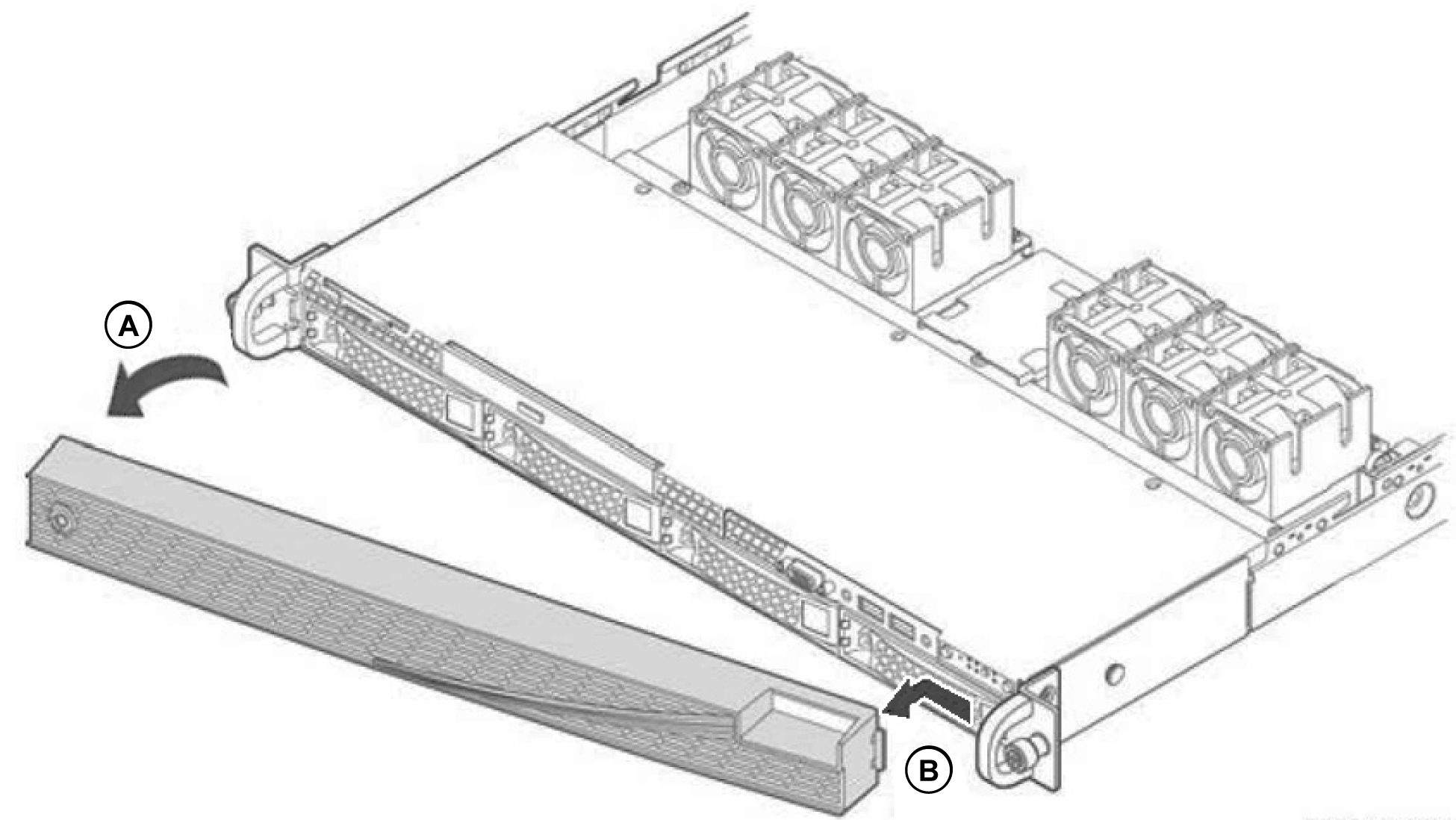
To remove the bezel
1. If locked, unlock the bezel.
2. Remove the left end of the front bezel from the rack handle (
Removing the bezel, letter A).
3. Pull the left side of the front bezel toward you to release the latches on the right end from the rack handle (
Removing the bezel, letter B).
Removing the bezel
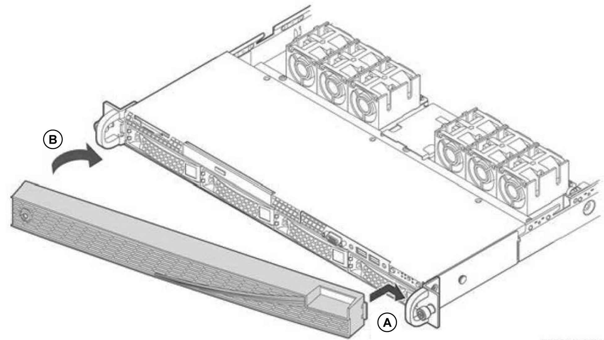
To install the bezel
1. Insert the tab on the right end of the front bezel to the rack handle (
Installing the bezel, letter A).
2. Push the left end of the bezel toward the gateway until it clicks into place (
Installing the bezel, letter B).
3. Lock the bezel, if needed.
Installing the bezel
Removing and installing the chassis cover
You need to remove the top cover to add or replace the components inside the gateway. This section describes how to work with the chassis cover.
The gateway must be operated with the gateway cover in place to ensure proper cooling.
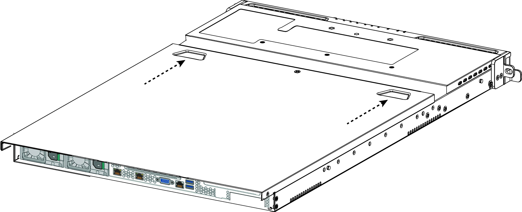
Removing the chassis cover
1. Power down the gateway and unplug all peripheral devices and the power cable.
2. Remove the screw, if there is one, on the cover and loosen the two captive screws on the rear panel of the cover.
Removing the cover
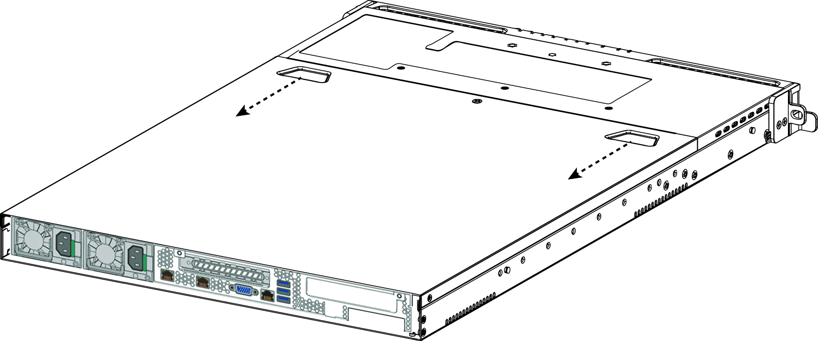
3. Slide the cover back and lift upward.
Installing the chassis cover
1. Place the top cover on the gateway and slide it toward the front of chassis until the recessed front edge fits smoothly under the chassis edge and the locking pins are fully engaged.
Installing the cover
2. Install the two captive installation screws at the rear of the unit and then secure the screw at the top if there is a screw.
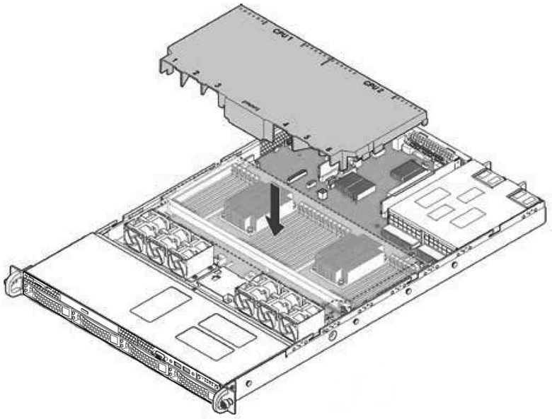
Removing and installing the air duct
The gateway requires an air duct for proper airflow. Always operate your gateway with the air duct in place.
You need to remove the air duct to access many internal components.
To remove and install the air duct
1. The air duct is located on top of the fans. Lift the air duct straight up to remove it from the gateway.
2. Align the air duct over the fans and lower the air duct into place to reinstall the air duct.
Installing the air duct
Replacing disk drives
This section describes how to remove and replace the disk drives.
If you need to replace a gateway, you cannot move the disks to preserve your data. Each disk is encoded with machine-level information and moving disks is not supported.
The SDI-2030 and SDI-5030 gateways are equipped with replaceable, hot-swappable, 3.5-inch hard-disk drives (HDD). When replacing a drive, replace only one drive at a time. You must use approved disk drives. To order disk drives, contact Riverbed Support at https://support.riverbed.com.
When you replace disk drives, you must wear a grounded ESD antistatic strap to protect the hardware against electrostatic discharge. Make sure that the strap makes skin contact prior to handling equipment.

Use caution when you remove or replace gateway components; they can become hot to the touch.
To replace a disk drive
1. Remove the bezel.
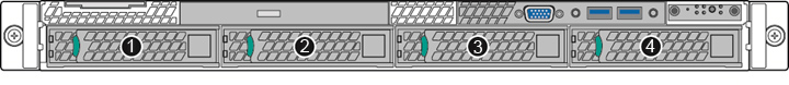
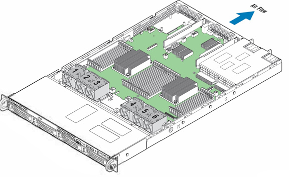
Disk drive numbers
3. Press the orange release button and pull the drive handle toward you.
Removing the disk drive
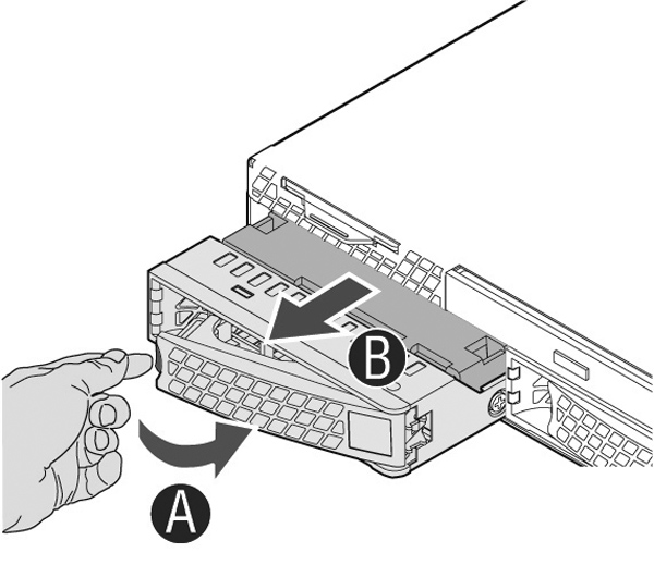
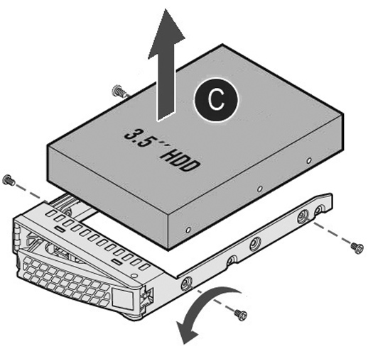
4. Slide the faulty disk drive out of the slot.
5. Remove the four screws securing the drive from the carrier and remove the failed drive.
Removing the drive from the carrier
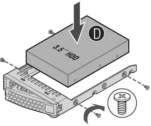
6. Insert the new drive in the carrier and secure using the four screws.
Make sure the drive connector matches the backplane connector.
Inserting the drive in the carrier
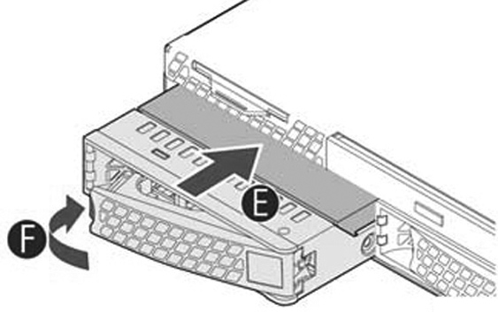
7. Open the new disk-drive handle by pressing the orange release button.
8. Slide in the new disk drive until it mates with the back connectors in the chassis.
The disk drive LED lights blue when connected.
Inserting the disk drive
9. Press in the disk-drive handle to close it.
The new disk drive runs through a self-test automatically. The disk drive automatically begins proper operation with the other disk drives. You do not need to set up or configure the new disk drive.
It takes approximately 3 to 4 hours to rebuild a new disk drive. You can configure the system to send an email to the administrator user when the disk drive has finished rebuilding.
Replacing memory modules
Memory module slot locations illustrates the memory module slot locations.
Memory module slot locations
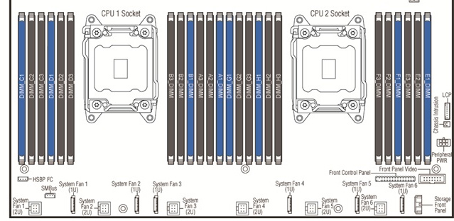
In the SDI-2030 the DIMM slots E1, E2, E3,G1, G2, and G3 are empty as there is no CPU in socket 2.
SDI-2030 empty CPU 2 socket and empty DIMM slots
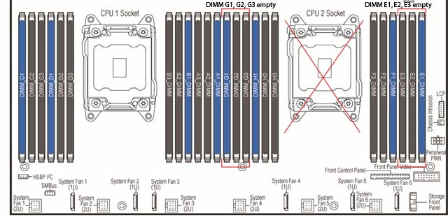
When adding new memory to the gateway, add the memory in the blue slots first. Once the blue slots are full, populate the black slots. Use the lowest lettered and numbered slots first.
To replace a memory module in the gateway
1. Power down the gateway.
2. Remove the chassis cover.
3. Remove the air duct.
4. Press the ejector tabs on the memory slots down and outward, and gently pull the memory module out of the slot.
5. Replace the memory module with an approved memory module of the same size.
Replacing the existing memory module with a module of a different size causes the gateway to fail. You must use approved memory modules. Contact Riverbed Support at https://support.riverbed.com to obtain the correct memory modules.
6. Align the memory-module edge connector with the slot alignment keys and insert it into the slot.
The module slot has two alignment keys that allow you to install the module in only one direction.
Inserting the memory modules into the connector slot and securing
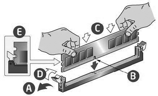
7. Press down on the memory module with your thumbs while pulling up on the ejectors with your index fingers to lock the module into the slot.
8. Ensure that all ejector tabs are in the upright locked position.
9. Replace the chassis cover.
10. Replace the power cords and peripherals.
11. Power on the gateway.
Replacing power supply units
This section describes how to replace a power supply. This gateway is equipped with replaceable, hot-swappable power supply units.
Use caution when replacing the power supply units; they can become hot to the touch.
To replace a power supply unit
1. Locate the defective power supply unit and remove the power cord.
2. Press the release tab toward the black handle, and pull the power supply unit toward you.
Removing the power supply unit
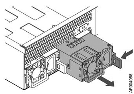
Power supply 1 (PS1) is on the left, and power supply 2 (PS2) is on the right.
3. Pull the power supply unit out of the chassis.
Put the defective power supply unit aside; wait until it cools down before touching it.
4. Slide in the new power supply unit until it clicks into place.
Inserting the power supply unit
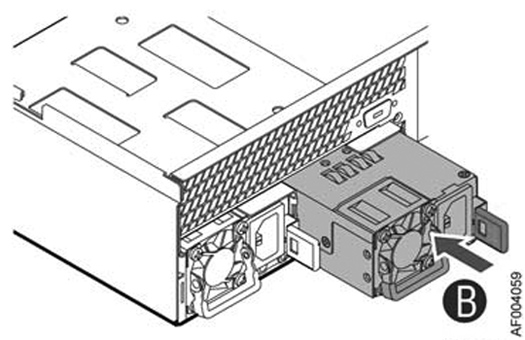
5. Plug the AC power cord into the new power supply unit.
Replacing fans
This section describes how to replace fans in the gateway. The gateways are equipped with six fans that are not hot swappable. You must power down the gateway before replacing the fans.
You must use approved fans. To order fans, contact Riverbed Support at https://support.riverbed.com.
To replace a fan
1. Power off the gateway and remove the chassis cover.
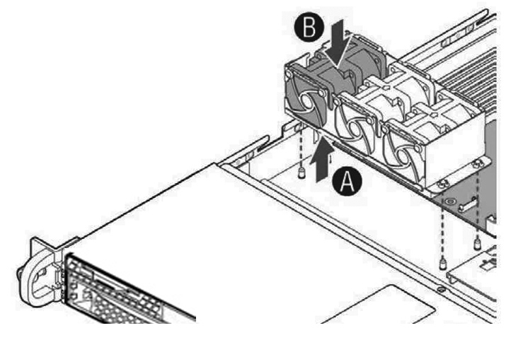
2. Identify the faulty fan. Disconnect the fan cable from the cable jack on the motherboard and remove the faulty fan from the dock.
Fan numbering
3. Lift the fan assembly from the chassis and push out the faulty fan.
Removing the fan assembly
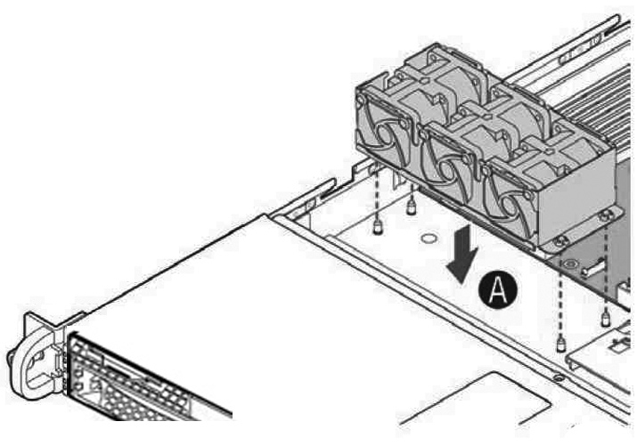
4. Install the replacement fan into the fan assembly, ensuring all the rubber guides are in place and the cable is located on the side closest to the server board.
5. Align the fan assembly mounting holes with pins on the chassis base and push down until it is firmly seated.
Installing the fan assembly
6. Attach the fan cable to the fan connector on the server board.
7. Replace the chassis cover.
Installing or replacing network interface cards (NICs)
In the SDI-5030 and SDI-2030 gateways, PCIe riser-card slot 1 is open for configuration with any of the supported NICs. For details on supported NICs, see
Supported SDI-2030 and SDI-5030 Gateway NICs To install or replace a NIC
1. Power down the gateway and remove the power-supply cord.
2. Remove the cables connected to the gateway.
3. Remove the gateway from the mounting rack, if necessary.
PCI risers
To install a card in the PCI riser
1. Remove the riser with the bracket by removing the screw.
2. If you are replacing an existing card, carefully pull the card from the riser. If you are not replacing a card, remove the filler panel from the slot by pushing it from the inside of the gateway.
3. Hold the new card between the front bezel and the rear of the card to avoid ESD damage.
4. Plug the assembly into the riser slot on the baseboard and fasten the screw.
Installing a PCI adapter to the riser assembly
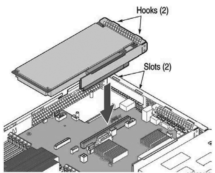
Make sure the cards are seated properly in the enclosure. The cards are not functional if they are not seated properly.
5. Replace the cover on the chassis.
6. Connect the power cords.
7. Connect the cables.
8. Power up the gateway and check the status lights.