Front panel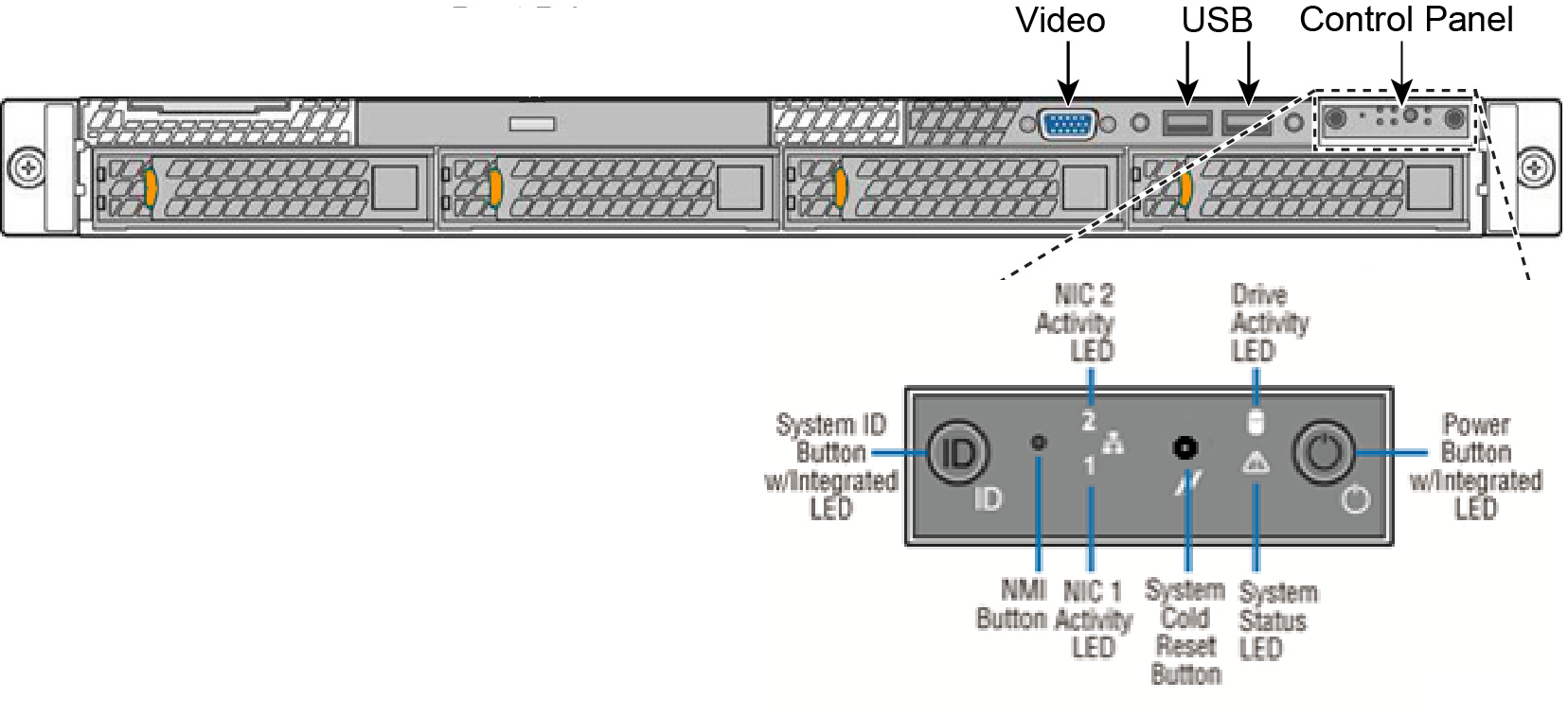
Components | Description |
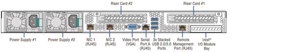
Power supply 1 and 2 | Supplies power to the gateway. |
Riser-card slot 1 | PCIe expansion slot. |
Riser-card slot 2 | Not configurable. |
VGA | DB15 access port used for video connectivity. |
Serial | RJ45 access port for communication input and output. |
USB | Three stacked ports that are 2.0 and 3.0 compatible. |
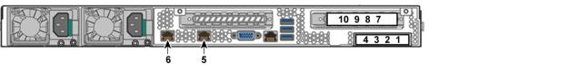
Ports 1 to 4 (SDI-5030) | Preinstalled with Four-Port 1-GbE Copper Base-T NIC. Port 1 reserved for SCM communication; port 2 reserved for cluster communication. The remaining ports are general purpose. |
Ports 1 to 4 (SDI-2030) | Preinstalled with Four-Port 1-GbE Copper Base-T NIC. Upon bootstrap, port 1 reserved for high availability (HA) and all remaining ports are used as uplinks. After the appliance establishes communication with SCM, any port can be used as either an HA port or an uplink (WAN) port. |
Ports 5 and 6 | Support for 10-GbE NICs. |
Ports 7 to 10 | Support for additional NICs. |
Front panel LEDsControl panel descriptions | LED description |
System ID button with integrated LED | Maintenance = blue. Turns the integrated ID LED and the blue server board ID LED on and off. The ID LED identifies the gateway for maintenance when installed in a rack of similar appliances. You can also turn on and turn off the ID LED remotely by using the Intelligent Platform Management Interface (IPMI) chassis identify command, which causes the LED to blink for 15 seconds. A duplicate system ID LED is on the back of the gateway to the left of the video port. |
NMI button (recessed, tool required for use) | Puts the gateway in a halt state and issues a nonmaskable interrupt (NMI). This state helps when performing diagnostics for a given issue where a memory download is necessary to determine the cause of the problem. To prevent an inadvertent system halt, the NMI button is located behind the front control panel faceplate and is only accessible with the use of a small tipped tool such as a pin or paper clip. |
NIC 1 activity LED (port 6 activity LED) | Maps to port 6 on the rear panel. Link = green. Activity = blinking green. The blink rate is consistent with the amount of network activity. |
System cold reset button (recess, tool required for use) | Reboots the gateway. |
System status LED | Shows the current health of the server system. Healthy = green. Degraded = yellow. Critical = blinking yellow. |
Power button with integrated LED | System on = green. System off = no light. |
Hard drive activity LED | Activity = blinking green. |
NIC 2 activity LED (port 5 activity LED) | Maps to port 5 on the rear panel. Link = green. Activity = blinking green. The blink rate is consistent with the amount of network activity. |
HDD LED | State | Description |
Activity LED | Blinking green | Read/write activity. |
Disk fault LED | Orange | Failed disk. |
Blinking orange | RAID rebuild. |
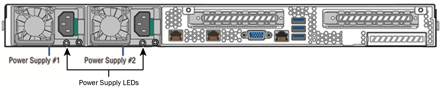 Back panel LEDs
Power supply LED state | Description |
Green | Power on. |
Off | No AC power to all power supplies. |
1 Hz blinking green | Standby AC present (only 12 VSB or power supply in cold redundant state). |
Amber | Power supply critical event causing a shutdown; failure OCP, OVP, fan fail. |
1 Hz blinking amber | Power supply warning (possible high temperature, high power, high current, slow fan). |
2 Hz blinking green | Power supply firmware updating. |
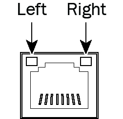
Port 5 and 6 LEDs | State | Description |
Left LED | Green | Link is up. |
Blinking green | Activity. | |
Right LED | No light (with green left LED) | 100 Mbps data rate. |
Green | 1000 Mbps data rate. | |
Yellow | 10 GbE data rate. |
Four-port 1-GbE copper LEDs | State | Description |
Speed/Disconnect (Top left) | Yellow | 1000 Mbps |
Green | 100 Mbps | |
Off | 10 Mbps | |
Link/Activity (Top right) | Green | Link |
Blinking green | Activity |