Configuring PBR
This section describes how to configure PBR and provides example deployments. This section includes the following topics:
Overview of Configuring PBRConfiguring a SteelHead to Directly Connect to the RouterConfiguring a SteelHead to Connect to a Layer-2 SwitchConfiguring a SteelHead to Connect to a Layer-3 SwitchConfiguring a SteelHead with Object TrackingConfiguring a SteelHead with Multiple PBR InterfacesConfiguring Multiple SteelHeads to Connect to Multiple RoutersConfiguring PBR for Load-Balancing WAN CircuitsConfiguring Local PBR for ICMP Redirection in a Mixed MTU EnvironmentOverview of Configuring PBR
You can use access lists to specify which traffic is redirected to the SteelHead. Traffic that is not specified in the access list is switched normally. If you do not have an access list, or if your access list is not correctly configured in the route map, traffic is not redirected.
For information about access lists, see
Configuring Access Control Lists.
Riverbed recommends that you define a policy based on the source or destination IP address rather than on the TCP source or destination ports, because certain protocols use dynamic ports instead of fixed ones.
Configuring a SteelHead to Directly Connect to the Router
Figure 12‑1 shows a SteelHead deployment in which the SteelHead is configured with PBR and is directly connected to the router.
Figure 12‑1. SteelHead Directly Connected to the Router
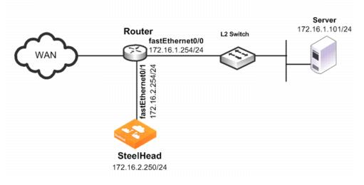
In this example:
The router fastEthernet0/0 interface is attached to the Layer-2 switch.The router fastEthernet0/1 interface is attached to the SteelHead.A single SteelHead is configured. You can add more SteelHeads using the same method as for the first SteelHead.Although the primary interface is not included in this example, Riverbed recommends, as a best practice, that you connect the primary interface for management purposes.
You must configure subnet side rules when you use RSP or VSP in a virtual in-path deployment. To configure subnet side rules, select Networking > Networking: Subnet Side Rules. VSP is enabled by default in the SteelHead EX series.
For information about configuring the primary interface, see the SteelHead Management Console User’s Guide.
To configure a SteelHead with PBR connected directly to the router
Connect to the SteelHead CLI and enter the following commands:
enable
configure terminal
in-path enable
in-path oop enable
interface in-path0_0 ip address 172.16.2.250/24
ip in-path-gateway inpath0_0 172.16.2.254
write memory
restart
You must save your changes or they are lost upon reboot. Restart the optimization service for the changes to take effect.
On the PBR router, at the system prompt, enter the following commands:
enable
configure terminal
route-map riverbed
match ip address 101
set ip next-hop 172.16.2.250
exit
ip access-list extended 101
permit tcp any 172.16.1.101 0.0.0.0
permit tcp 172.16.1.101 0.0.0.0 any
exit
interface fa0/0
ip policy route-map riverbed
interface S0/0
ip policy route-map riverbed
exit
exit
write memory
Enter one configuration command per line. Press Ctrl-Z to end the configuration.
Configuring a SteelHead to Connect to a Layer-2 Switch
Figure 12‑2 shows a SteelHead deployment in which the SteelHead is configured with PBR and is directly connected to the router through a switch. This deployment also has a trunk between the switch and the router.
Figure 12‑2. SteelHead Connected to a Layer-2 Switch with a VLAN
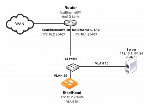
In this example:
The switch logically separates the server and the SteelHead by placing:the server on VLAN 10.the SteelHead on VLAN 20.The router fastEthernet0/1 interface is attached to the Layer-2 switch.The router performs inter-VLAN routing; that is, the router switches packets from one VLAN to the other. The link between the router and the switch is configured as a dot1Q trunk to transport traffic from multiple VLANs.Although the primary interface is not included in this example, Riverbed recommends that you connect the primary interface for management purposes.
For information about configuring the primary interface, see the SteelHead Management Console User’s Guide.
To configure a SteelHead with PBR to a connected Layer-2 switch with a VLAN to the router
Connect to the SteelHead CLI and enter the following commands:
enable
configure terminal
in-path enable
in-path oop enable
interface in-path0_0 ip address 172.16.2.250/24
ip in-path-gateway inpath0_0 172.16.2.254
write memory
restart
You must save your changes or they are lost upon reboot. Restart the optimization service for the changes to take effect.
On the PBR router, at the system prompt, enter the following commands:
enable
configure terminal
route-map riverbed
match ip address 101
set ip next-hop 172.16.2.250
exit
ip access-list extended 101
permit tcp any 172.16.1.101 0.0.0.0
permit tcp 172.16.1.101 0.0.0.0 any
exit
interface fa0/1.10
encapsulation dot1Q 10
ip address 172.16.1.254 255.255.255.0
interface fa0/1.20
encapsulation dot1Q 20
ip address 172.16.2.254 255.255.255.0
exit
interface fa0/1.10
ip policy route-map riverbed
interface S0/0
ip policy route-map riverbed
exit
exit
write memory
Tip: Enter one configuration command per line. Press Ctrl-Z to end the configuration.
In this example, assume that both the SteelHead and the server are connected to the correct VLAN. Also assume that these VLAN connections are established through the switch port configuration on the Layer-2 switch.
Configuring a SteelHead to Connect to a Layer-3 Switch
Figure 12‑3 shows a SteelHead deployment in which the SteelHead is configured with PBR and is directly connected to a Layer-3 switch.
Figure 12‑3. SteelHead Connected to a Layer-3 Switch
In this example:
The Layer-3 switch fastEthernet0/0 interface is attached to the server and is on VLAN 10.The Layer-3 switch fastEthernet0/1 interface is attached to the SteelHead and is on VLAN 20. A single SteelHead is configured. You can add more appliances using the same method as used for the first SteelHead.Although the primary interface is not included in this example, Riverbed recommends that you connect the primary interface for management purposes. For information about configuring the primary interface, see the SteelHead Management Console User’s Guide.
To configure a SteelHead with PBR connected directly to a Layer-3 switch
Connect to the SteelHead CLI and enter the following commands:
enable
configure terminal
in-path enable
in-path oop enable
in-path cdp enable
interface in-path0_0 ip address 172.16.2.250/24
ip in-path-gateway inpath0_0 172.16.2.254
write memory
restart
You must save your changes or they are lost upon reboot. Restart the optimization service for the changes to take effect.
On the Layer-3 switch, at the system prompt, enter the following commands:
enable
configure terminal
route-map riverbed
match ip address 101
set ip next-hop 172.16.2.250
set ip next-hop verify-availability
exit
ip access-list extended 101
permit tcp any 172.16.1.101 0.0.0.0
permit tcp 172.16.1.101 0.0.0.0 any
exit
interface vlan 10
ip address 172.16.1.254 255.255.255.0
ip policy route-map riverbed
interface vlan 20
ip address 172.16.2.254 255.255.255.0
interface vlan 30
ip policy route-map riverbed
exit
exit
write memory
Tip: Enter one configuration commands per line. Press Ctrl-Z to end the configuration.
Configuring a SteelHead with Object Tracking
In an object tracking deployment, the SteelHead is connected to the router, and the router tracks whether the SteelHead is reachable using the Object Tracking feature of Cisco IOS. Object Tracking enables you to use methods such as HTTP GET and ping, to determine whether the PBR next-hop IP address is available.
Object Tracking is not available on all Cisco devices. For information about whether your Cisco device supports this feature, refer to your router documentation.
To configure the SteelHead with object tracking
For diagram details, see
Figure 12‑1.
Connect to the SteelHead CLI and enter the following commands:
enable
configure terminal
interface in-path0_0 ip address 172.16.2.2
50/24
ip in-path-gateway inpath0_0 172.16.2.254
in-path enable
in-path oop enable
no interface inpath0_0 fail-to-bypass enable
write memory
On the PBR router, at the system prompt, enter the following commands:
enable
configure terminal
ip sla 1
icmp-echo 172.16.2.250
ip sla schedule 1 life forever start-time now
track 101 rtr 1 reachability
route-map riverbed
match ip address 101
set ip next-hop verify-availability 172.16.2.250 10 track 101
exit
ip access-list extended 101
permit tcp any 172.16.1.101 0.0.0.0
permit tcp 172.16.1.101 0.0.0.0 any
exit
interface fa0/0
ip policy route-map riverbed
interface S0/0
ip policy route-map riverbed
exit
exit
write memory
Configuring a SteelHead with Multiple PBR Interfaces
In a deployment that uses multiple PBR interfaces, the SteelHead is connected to two routers, each of which is configured to redirect traffic to a separate interface on the SteelHead. Each router is configured similarly to the single router deployment, except that you specify a next-hop IP address that corresponds to the interface to which the SteelHead connects.
To configure the SteelHead with multiple PBR interfaces
For diagram details, see
Figure 12‑1.
Connect to the SteelHead CLI and enter the following commands:
enable
configure terminal
in-path enable
Interface inpath0_1 enable
in-path oop enable
interface in-path0_0 ip address 172.16.2.250/24
ip in-path-gateway inpath0_0 172.16.2.254
interface in-path0_1 ip address 172.16.3.250/24
ip in-path-gateway inpath0_1 172.16.3.254
write memory
restart
You must save your changes or they are lost upon reboot. Restart the optimization service for the changes to take effect.
On the first PBR router, at the system prompt, enter the following commands:
enable
configure terminal
route-map riverbed
match ip address 101
set ip next-hop 172.16.2.250
exit
ip access-list extended 101
permit tcp any 172.16.1.101 0.0.0.0
permit tcp 172.16.1.101 0.0.0.0 any
exit
interface fa0/0
ip policy route-map riverbed
interface S0/0
ip policy route-map riverbed
exit
exit
write memory
On the second PBR router, at the system prompt, enter the following commands:
enable
configure terminal
route-map riverbed
match ip address 101
set ip next-hop 172.16.3.250
exit
ip access-list extended 101
permit tcp any 172.16.1.101 0.0.0.0
permit tcp 172.16.1.101 0.0.0.0 any
exit
interface fa0/0
ip policy route-map riverbed
interface S0/0
ip policy route-map riverbed
Configuring Multiple SteelHeads to Connect to Multiple Routers
In a PBR environment, you can deploy multiple SteelHeads for optimization redundancy.
Figure 12‑4 shows a SteelHead deployment in which two routers are redirecting packets to two SteelHeads. The SteelHeads are directly connected through multiple interfaces. This deployment provides a high-availability environment—a full-mesh topology between the routers and SteelHeads.
When you deploy multiple SteelHeads, the routers can redirect packets within a TCP connection to different SteelHeads, depending on the router policy. For example, Router A redirects packets to SteelHead A. Following network convergence due to a WAN outage packets for this TCP connection, the packets arrive on Router B. Router B has a policy configured to redirect packets to SteelHead B. In this type of environment, Riverbed recommends that you use connection forwarding to ensure packets within a flow are forwarded to the owning SteelHead for optimization.
For more information about connection forwarding, see
Connection Forwarding.
Data store synchronization is not a requirement for SteelHeads in a PBR environment, but it is useful if your design goal is for warm performance after a SteelHead fails. To use data store synchronization, you must meet certain criteria.
For more information about the data store, see
RiOS Data Store Synchronization.
Figure 12‑4. Multiple SteelHeads Directly Connected to Dual Routers
The example in
Figure 12‑4 shows the following:
You can redirect packets to SteelHead interfaces in any order.
Figure 12‑4 shows Router A redirecting packets first to SteelHead A inpath0_0, and then to SteelHead B inpath0_1; and Router B redirecting packets first to SteelHead B inpath0_0 then SteelHead A inpath0_1. Router A and Router B can redirect to SteelHead A inpath0_0 and inpath0_1 respectively.
This example shows two SteelHeads. You can add more SteelHeads using a similar method as for the first SteelHead.
To configure dual SteelHeads with PBR connected to dual routers
Connect to SteelHead A CLI and enter the following commands:
enable
configure terminal
in-path enable
in-path oop enable
interface in-path0_0 ip address 172.16.2.250/24
ip in-path-gateway inpath0_0 172.16.2.254
interface in-path0_1 ip address 172.16.3.250/24
ip in-path-gateway inpath0_1 172.16.3.254
in-path neighbor enable
in-path neighbor multi-interface enable
in-path name SteelHeadB main-ip 172.16.3.250
in-path name SteelHeadB additional-ip 172.16.4.250
in-path neighbor allow-failure
no interface inpath0_0 fail-to-bypass enable
no interface inpath0_1 fail-to-bypass enable
write memory
restart
You must save your changes or they are lost upon reboot. Restart the optimization service for the changes to take effect.
Connect to SteelHead B CLI and enter the following commands:
enable
configure terminal
in-path enable
in-path oop enable
interface in-path0_0 ip address 172.16.2.250/24
ip in-path-gateway inpath0_0 172.16.2.254
interface in-path0_1 ip address 172.16.3.250/24
ip in-path-gateway inpath0_1 172.16.3.254
in-path neighbor enable
in-path neighbor multi-interface enable
in-path name SteelHeadA main-ip 172.16.2.250
in-path name SteelHeadA additional-ip 172.16.5.250
in-path neighbor allow-failure
no interface inpath0_0 fail-to-bypass enable
no interface inpath0_1 fail-to-bypass enable
write memory
restart
You must save your changes or they are lost upon reboot. Restart the optimization service for the changes to take effect.
On Router A, at the system prompt, enter the following commands:
enable
configure terminal
route-map riverbed
match ip address 101
set ip next-hop 172.16.2.250 172.16.5.250
exit
ip access-list extended 101
permit tcp any 172.16.1.101 0.0.0.0
permit tcp 172.16.1.101 0.0.0.0 any
exit
interface fa2/0
ip address 172.16.2.254 255.255.255.0
interface fa3/0
ip address 172.16.5.254 255.255.255.0
exit
interface fa1/0
ip policy route-map riverbed
interface S0/0
ip policy route-map riverbed
exit
exit
write memory
On Router B, at the system prompt, enter the following commands:
enable
configure terminal
route-map riverbed
match ip address 101
set ip next-hop 172.16.4.250 172.16.3.250
exit
ip access-list extended 101
permit tcp any 172.16.1.101 0.0.0.0
permit tcp 172.16.1.101 0.0.0.0 any
exit
interface fa2/0
ip address 172.16.3.254 255.255.255.0
interface fa3/0
ip address 172.16.4.254 255.255.255.0
exit
interface fa1/0
ip policy route-map riverbed
interface S0/0
ip policy route-map riverbed
exit
exit
write memory
Configuring PBR for Load-Balancing WAN Circuits
In a network with multiple entry and exit points, you can configure the router and SteelHead to support two goals:
Support peer affinity so one SteelHead more efficiently optimizes the traffic for a remote peerMaintain outbound load balancing by allowing the SteelHeads to use separate WAN circuits to reach the remote sitesFigure 12‑5 shows all SteelHeads in one subnet. The routers are configured with access control lists (ACLs) to direct traffic from remote peer A to SteelHead A, and traffic for remote peer B to SteelHead B. The failover method is object tracking. An optional all-inclusive rule is added to simplify the addition of a new remote site. To support outbound load balancing, each SteelHead uses a different default gateway.
Optimized traffic from SteelHead A reaches the WAN through Router A, and SteelHead B reaches the WAN through router B. Multiple HSRP (MHSRP) allows the routers to present two default gateways for the WAN optimization subnet, at the same time having redundancy in case a WAN circuit fails. Instead of MHSRP, you could use Gateway Load Balancing Protocol (GLBP) or static routes on the SteelHeads. If you use one of these two methods, the SteelHeads are unaware of a WAN circuit outage.
Figure 12‑5. PBR Load-Balancing
In this example:
Each router fastEthernet2/0 interface and SteelHead wan0_0 interface are attached to same VLAN on the switch.Each router uses object tracking to bypass the PBR next-hop statement because the SteelHeads are not directly connected to the router. Embedded event manager is another option.CDP frames from the SteelHead are consumed by the switch and do not reach the routers. This renders CDP ineffective for failover.
Packets are redirected to a SteelHead based on remote IP address subnet for peer affinity.Multiple HSRP groups are used on the router fastEthernet2/0 interfaces to achieve outbound load balancing on the WAN. (Gateway load balancing protocol, or configuring static routes on the SteelHead in-path interface can be used instead of multiple HSRP.) Router WAN interfaces are tracked when using HSRP to ensure the router has a path to the remote site.Multi-interface is enabled in case another SteelHead interface is connected to another WAN optimization subnet.Two SteelHeads are configured in this example. You can add more SteelHeads using the same method as used for one of the SteelHeads ensuring policy route statements, any ACLs, default gateway align with load-balancing and redundancy goals.
To configure PBR appliances in a load-balanced environment
Connect to SteelHead A CLI and enter the following commands:
enable
configure terminal
in-path enable
in-path oop enable
interface in-path0_0 ip address 172.16.2.250/24
ip in-path-gateway inpath0_0 172.16.2.254
in-path neighbor enable
in-path neighbor multi-interface enable
in-path name SteelHeadB main-ip 172.16.2.251
in-path neighbor allow-failure
no interface inpath0_0 fail-to-bypass enable
write memory
restart
You must save your changes or they are lost upon reboot. Restart the optimization service for the changes to take effect.
Connect to SteelHead B CLI and enter the following commands:
enable
configure terminal
in-path enable
in-path oop enable
interface in-path0_0 ip address 172.16.2.251/24
ip in-path-gateway inpath0_0 172.16.2.253
in-path neighbor enable
in-path neighbor multi-interface enable
in-path name SteelHeadA main-ip 172.16.2.250
in-path neighbor allow-failure
no interface inpath0_0 fail-to-bypass enable
write memory
restart
You must save your changes or they are lost upon reboot. Restart the optimization service for the changes to take effect.
On PBR router A, at the system prompt, enter the following commands:
enable
configure terminal
ip access-list extended Remotes-To-A
permit tcp address 10.1.100.0 0.0.0.255 any
permit tcp address any 10.1.100.0 0.0.0.255
exit
ip access-list extended Remotes-To-B
permit tcp address 10.1.200.0 0.0.0.255 any
permit tcp address any 10.1.200.0 0.0.0.255
exit
ip access-list extended Catch-All
permit tcp any 172.16.1.101 0.0.0.0
permit tcp 172.16.1.101 0.0.0.0 any
exit
ip sla 1
icmp-echo 172.16.2.250 source-interface fastEthernet2/0
exit
ip sla schedule 1 life forever start-time now
ip sla 2
icmp-echo 172.16.2.251 source-interface fastEthernet2/0
exit
ip sla schedule 2 life forever start-time now
track 1 ip sla 1 reachability
track 2 ip sla 2 reachability
track 100 interface S0/0 line-protocol
route-map riverbed permit 10
match ip address Remotes-To-A
set ip next-hop verify-availability 172.16.2.250 1 track 1
set ip next-hop verify-availability 172.16.2.251 2 track 2
route-map riverbed permit 20
match ip address Remotes-To-B
set ip next-hop verify-availability 172.16.2.251 1 track 2
set ip next-hop verify-availability 172.16.2.250 2 track 1
route-map riverbed permit 30
match ip address Catch-All
set ip next-hop verify-availability 172.16.2.250 1 track 1
set ip next-hop verify-availability 172.16.2.251 2 track 2
exit
interface fa2/0
ip address 172.16.2.1 255.255.255.0
standby 1 ip 172.16.2.254
standby 1 priority 110
standby 1 preempt
standby 1 track 100 20
standby 2 ip 172.16.2.253
standby 2 preempt
exit
interface fa1/0
ip policy route-map riverbed
interface S0/0
ip policy route-map riverbed
exit
exit
write memory
On PBR Router B, at the system prompt, enter the following commands:
enable
configure terminal
ip access-list extended Remotes-To-A
permit tcp address 10.1.100.0 0.0.0.255 any
permit tcp address any 10.1.100.0 0.0.0.255
exit
ip access-list extended Remotes-To-B
permit tcp address 10.1.200.0 0.0.0.255 any
permit tcp address any 10.1.200.0 0.0.0.255
exit
ip access-list extended Catch-All
permit tcp any 172.16.1.101 0.0.0.0
permit tcp 172.16.1.101 0.0.0.0 any
exit
ip sla 1
icmp-echo 172.16.2.250 source-interface fastEthernet2/0
exit
ip sla schedule 1 life forever start-time now
ip sla 2
icmp-echo 172.16.2.251 source-interface fastEthernet2/0
exit
ip sla schedule 2 life forever start-time now
track 1 ip sla 1 reachability
track 2 ip sla 2 reachability
track 100 interface S0/0 line-protocol
route-map riverbed permit 10
match ip address Remotes-To-A
set ip next-hop verify-availability 172.16.2.250 1 track 1
set ip next-hop verify-availability 172.16.2.251 2 track 2
route-map riverbed permit 20
match ip address Remotes-To-B
set ip next-hop verify-availability 172.16.2.251 1 track 2
set ip next-hop verify-availability 172.16.2.250 2 track 1
route-map riverbed permit 30
match ip address Catch-All
set ip next-hop verify-availability 172.16.2.250 1 track 1
set ip next-hop verify-availability 172.16.2.251 2 track 2
exit
interface fa2/0
ip address 172.16.2.2 255.255.255.0
standby 1 ip 172.16.2.254
standby 1 preempt
standby 2 ip 172.16.2.253
standby 2 priority 110
standby 2 preempt
standby 2 track 100 20
exit
interface fa1/0
ip policy route-map riverbed
interface S0/0
ip policy route-map riverbed
exit
exit
write memory
Configuring Local PBR for ICMP Redirection in a Mixed MTU Environment
You can add a Local PBR configuration in addition to the regular PBR configuration discussed in previous sections. You use a Local PBR configuration in environments where ICMP messages generated by the router need special routing configurations: for example, mixed-size maximum transmission unit (MTU) environment with SteelHead full-transparency in-path rules.
In networks that have a mix of MTU interface configurations, path MTU (PMTU) discovery determines the MTU size on the network path between two IP hosts, to avoid IP fragmentation. Network routers send ICMP Fragment needed but do not fragment bit set messages and packets back to the sending host; the host then decreases the segment size and retransmits the segment.
You must forward ICMP packets to the correct host (the client, server, or SteelHead). In some network scenarios, you need a Local PBR configuration to ensure ICMP messages, generated by a router, are redirected out of the same interface of the inbound IP datagram that triggers the ICMP message. Cisco Local PBR is a local policy route map configuration that can achieve this.
Figure 12‑6 shows an example scenario for which you can configure Local PBR.
Figure 12‑6. Local PBR Configuration
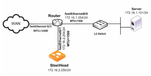
In this example, the:
router fastEthernet0/0 interface is attached to the layer-2 switch. The MTU is configured for 1500 bytes.router fastEthernet0/1 interface is attached to the SteelHead. The MTU is configured for 1500 bytes.router fastEthernet 0/2 interface is attached to the WAN. The MTU is configured for 1400 bytes.SteelHead is configured to optimize with full transparency.Without a Local PBR configuration on the router, optimized connections on the SteelHead can attempt to send IP datagrams of 1500 bytes across the WAN. Due to PMTU discovery, the router generates an ICMP fragment needed but do not fragment bit set message.
Because the SteelHead is configured with full transparency, the router forwards the ICMP message back to the server instead of the SteelHead. This results in the server reducing its segment size for the connection, when in fact, the SteelHead must be the one to reduce its segment size. This confusion results in transfer failure.
You can use the following Local PBR configuration on the router to ensure that packets received on fastethernet0/1, and trigger any ICMP message on the router, are forwarded to the SteelHead.
To configure Local PBR on the router
On the PBR router, at the system prompt, enter the following commands:Enable
Configure terminal
ip local policy route-map local_pbr_1
access-list 101 permit icmp host 172.16.2.254 any
route-map local_pbr_1 permit 10
match ip address 101
set ip next-hop 172.16.2.250
exit
exit
write memory