Modifying the base interfaces
Appliance conditions | No SSH/HTTPS channels | There is SSH/HTTPS channel already over IPv4 | There is SSH/HTTPS channel already over IPv6 |
SteelHead & SCC reachable over IPv4 and IPv6 | To establish an SSH/HTTPS channels: scc hostname <ip-address> scc enable | Until the existing SSH/HTTPS channel is broken explicitly the IPv4 SSH/HTTPS channel will continue to exist. Break the channels using the procedures described above. To reestablish the SSH/HTTPS channels: scc hostname <ip-address> scc enable | Until the existing SSH/HTTPS channel is broken explicitly the IPv6 SSH/HTTPS channel will continue to exist. Break the channels using the procedures described above. To reestablish the SSH/HTTPS channels: scc hostname <ip-address> scc enable |
SteelHead & SCC reachable over IPv4 only | To establish the SSH/HTTPS channel over IPv4: scc hostname <ip-address> scc enable | To establish the SSH/HTTPS channel over IPv4: scc hostname <ip-address> scc enable | Not applicable |
SteelHead & SCC reachable over IPv6 only | To establish the SSH/HTTPS channel over IPv6: scc hostname <ip-address> scc enable | Not applicable | To establish the SSH/HTTPS channel over IPv6: scc hostname <ip-address> scc enable |
Control | Description |
Primary DNS Server | Specify the IP address for the primary name server. The IP address can be either IPv4 or IPv6. For IPv6 specify an IP address using this format: eight 16-bit hexadecimal strings separated by colons, 128-bits. For example: 2001:38dc:0052:0000:0000:e9a4:00c5:6282 You don’t need to include leading zeros. For example: 2001:38dc:52:0:0:e9a4:c5:6282 You can replace consecutive zero strings with double colons (::). For example: 2001:38dc:52::e9a4:c5:6282 |
Secondary DNS Server | Optionally, specify the IP address for the secondary name server. |
Tertiary DNS Server | Optionally, specify the IP address for the tertiary name server. |
DNS Domain List | Specify an ordered list of domain names. If you specify domains, the system automatically finds the appropriate domain for each of the hosts that you specify in the system. |
Control | Description |
Add a New Host | Displays the controls for adding a new host. |
IP Address | Specify the IP address, either IPv4 or IPv6, for the host. For IPv6 specify an IP address using this format: eight 16-bit hexadecimal strings separated by colons, 128-bits. For example: 2001:38dc:0052:0000:0000:e9a4:00c5:6282 You don’t need to include leading zeros. For example: 2001:38dc:52:0:0:e9a4:c5:6282 You can replace consecutive zero strings with double colons (::). For example: 2001:38dc:52::e9a4:c5:6282 |
Hostname | Specify a hostname. |
Add | Adds the host. |
Remove Selected | Select the check box next to the name and click Remove Selected. |
Apply | Applies your settings to the running configuration. |
Control | Description |
Enable Proxy Settings | Provides network proxy access to the SteelHead. Enables the SteelHead to use a proxy to contact the Riverbed licensing portal and fetch licenses in a secure environment. You can optionally require user credentials to communicate with the proxy, and you can specify the method used to authenticate and negotiate user credentials. Proxy access is disabled by default. RiOS supports these proxies: Squid, Blue Coat Proxy SG, Microsoft WebSense, and McAfee Web Gateway. |
Web/FTP Proxy | Specify the IP address, either IPv4 or IPv6, for the network or FTP proxy. For IPv6 specify an IP address using this format: eight 16-bit hexadecimal strings separated by colons, 128-bits. For example: 2001:38dc:0052:0000:0000:e9a4:00c5:6282 You don’t need to include leading zeros. For example: 2001:38dc:52:0:0:e9a4:c5:6282 You can replace consecutive zero strings with double colons (::). For example: 2001:38dc:52::e9a4:c5:6282 |
Port | Optionally, specify the port for the network or FTP proxy. The default port is 1080. |
Enable Authentication | Optionally, select to require user credentials for use with network or FTP proxy traffic. Specify these values to authenticate the users: •User Name - Specify a username. •Password - Specify a password. •Authentication Type - Select an authentication method from the drop-down list: –Basic - Authenticates user credentials by requesting a valid username and password. This is the default setting. –NTLM - Authenticates user credentials based on an authentication challenge and response. –Digest - Provides the same functionality as basic authentication; however, digest authentication improves security because the system sends the user credentials across the network as a Message Digest 5 (MD5) hash. |
Proxy Whitelist | Optionally, add or remove domains from a proxy whitelist. |
Apply | Applies your changes to the running configuration. |
Control | Description |
Enable Primary Interface | Enables the appliance management interface, which can be used for both managing the SCC and serving data for a server-side out-of-path (OOP) configuration. |
Obtain IPv4 Address Automatically | Displays multiple IPv4 values assigned by DHCP server. (A DHCP server must be available so that the system can request the IP address from it.) |
Enable IPv4 Dynamic DNS | Select this option to send the hostname with the DHCP request for registration with Dynamic DNS. |
Specify IPv4 Address Manually | Select this option if you don’t use a DHCP server to set the IPv4 address. Specify these settings: •IPv4 Address - Specify an IP address. •IPv4 Subnet Mask - Specify a subnet mask. •Default IPv4 Gateway - Specify the default gateway IPv4 address. The default gateway must be in the same network as the primary interface. You must set the default gateway for in-path configurations. |
Obtain IPv6 Address Automatically | Displays multiple IPv6 values assigned by DHCP server. (A DHCP server must be available so that the system can request the IP address from it.) Note: If you change the primary or aux interface from IPv4 to IPv6 you must restart the httpd service. From the SCC command line, run this command: pm process httpd restart |
Enable IPv6 Dynamic DNS | Select this option to send the hostname with the DHCP request for registration with Dynamic DNS. |
Specify IPv6 Address Manually | Select this option and specify these settings to set an IPv6 address. •IPv6 Auto-Assigned - Displays the link-local address that is automatically generated when IPv6 is enabled on the interface. •IPv6 Address - Specify a combination of both the IPv6 address and IPv6 prefix. Use this format: <IPv6-address>/<IPv6-prefix>. For example: 210::33/64 •Add a New IPv6 Address - This option allows you to configure multiple IPv6 Addresses to the interface. Use this format: <IPv6-address>/<IPv6-prefix>. New IPv6 addresses are displayed as an entry with this label: IPv6-<address>. •IPv6 Gateway - Specify the gateway IP address. The gateway must be in the same network as the primary interface. To modify an existing IPv6 address, empty the contents of the corresponding text field and click Apply. To delete an existing IPv6 address, update the contents of the corresponding text field and click Apply. Note: If you selected Specify IPv6 Address Manually and assigned multiple IP addresses to your interface, then if you select Obtain IPv6 Address Automatically and click Apply, all the IP address assigned manually will be deleted. Note: If you change the primary or aux interface from IPv4 to IPv6 you must restart the httpd service. From the SCC command line, run this command: pm process httpd restart |
MTU | Specify the MTU value. The MTU is the largest physical packet size, measured in bytes, that a network can send. The default value is 1500. |
Control | Description |
Enable Aux Interface | Enables an auxiliary interface, which can be used only for managing the SCC. Typically this is used for device-management networks. |
Obtain IPv4 Address Automatically | Displays multiple IPv4 values assigned by DHCP server. (A DHCP server must be available so that the system can request the IP address from it.) |
Enable IPv4 Dynamic DNS | Select this option to send the hostname with the DHCP request for registration with Dynamic DNS. |
Specify IPv4 Address Manually | Select this option if you don’t use a DHCP server to set the IPv4 address. Specify these settings: •IPv4 Address - Specify an IP address. •IPv4 Subnet Mask - Specify a subnet mask. |
Obtain IPv6 Address Automatically | Displays multiple IPv6 values assigned by DHCP server. (A DHCP server must be available so that the system can request the IP address from it.) Note: If you change the primary or aux interface from IPv4 to IPv6 you must restart the httpd service. From the SCC command line, run this command: pm process httpd restart |
Enable IPv6 Dynamic DNS | Select this option to send the hostname with the DHCP request for registration with Dynamic DNS. |
Specify IPv6 Address Manually | Select this option and specify these settings to set an IPv6 address. •IPv6 Auto-Assigned - Displays the link-local address that is automatically generated when IPv6 is enabled on the interface. •IPv6 Address - Specify a combination of both the IPv6 address and IPv6 prefix. Use this format: <IPv6-address>/<IPv6-prefix>. For example: 210::33/64 •Add a New IPv6 Address - This option allows you to configure multiple IPv6 Addresses to the interface. Use this format: <IPv6-address>/<IPv6-prefix>. New IPv6 addresses are displayed as an entry with this label: IPv6 -<address>. To modify an existing IPv6 address, update the contents of the corresponding text field and click Apply. To delete an existing IPv6 address, empty the contents of the corresponding text field and click Apply. Note: If you selected Specify IPv6 Address Manually and assigned multiple IP addresses to your interface, then if you select Obtain IPv6 Address Automatically and click Apply, all the IP address assigned manually will be deleted. Note: If you change the primary or aux interface from IPv4 to IPv6 you must restart the httpd service. From the SCC command line, run this command: pm process httpd restart |
MTU | Specify the MTU value. The MTU is the largest physical packet size, measured in bytes, that a network can send. The default value is 1500. |
Control | Description |
Add a New Route | Displays the controls for adding a new route. |
Destination IPv4 Address | Specify the destination IP address for the out-of-path appliance or network management device. |
IPv4 Subnet Mask | Specify the subnet mask. |
Gateway IPv4 Address | Specify the IP address for the gateway. The gateway must be in the same network as the primary or auxiliary interface you’re configuring. |
Interface | Select an interface for the IPv4 route from the drop-down list. |
Add | Adds the route to the table list. |
Remove Selected | Select the check box next to the name and click Remove Selected. |
Control | Description |
Add a New Route | Displays the controls for adding a new route. |
Destination IPv6 Address | Specify the destination IP address. |
IPv6 Prefix | Specify a prefix. The prefix length is from 0 to 128 bits, separated from the address by a forward slash (/). |
Gateway IPv6 Address | Specify the IP address for the gateway. The gateway must be in the same network as the primary or auxiliary interface you’re configuring. |
Interface | Select an interface for the IPv6 route from the drop-down list. |
Add | Adds the route to the table list. |
Remove Selected | Select the check box next to the name and click Remove Selected. |
Control | Description |
Login Message | Type a message in the text box to appear on the Login page. |
MOTD | Specify a message in the text box to appear in the Dashboard. |
Apply | Applies your settings to the running configuration. |
Control | Description |
CPU Utilization | Enables an alarm if the average and peak threshold for the CPU utilization is exceeded. When an alarm reaches the rising threshold, it is activated; when it reaches the lowest or reset threshold, it is reset. After an alarm is triggered, it isn’t triggered again until it has fallen below the reset threshold. By default, this alarm is enabled, with a rising threshold of 90 percent and a reset threshold of 80 percent. •Rising Threshold - Specify the rising threshold. When an alarm reaches the rising threshold, it is activated. The default value is 90 percent. •Reset Threshold - Specify the reset threshold. When an alarm reaches the lowest or reset threshold, it is reset. After an alarm is triggered, it isn’t triggered again until it has fallen below the reset threshold. The default value is 80 percent. |
Disk Full | Enables an alarm if the system partitions (not the RiOS data store) are full or almost full. For example, RiOS monitors the available space on /var, that’s used to hold logs, statistics, system dumps, TCP dumps, and so on. By default, this alarm is enabled. This alarm monitors these system partitions: •Partition "/boot Full" Free Space •Partition "/bootmgr Full" Free Space •Partition "/config Full" Free Space •Partition "/data Full" Free Space •Partition "/scratch Full" Free Space •Partition "/var Full" Free Space |
Hardware | Fan Error - Enables an alarm and sends an email notification if a fan is failing or has failed and needs to be replaced. By default, this alarm is enabled. Flash Error - Enables an alarm when the system detects an error with the flash drive hardware. By default, this alarm is enabled. IPMI - Enables an alarm and sends an email notification if an Intelligent Platform Management Interface (IPMI) event is detected (not supported on all appliance models). This alarm triggers when there has been a physical security intrusion. These events trigger this alarm: •Chassis intrusion (physical opening and closing of the appliance case) •Memory errors (correctable or uncorrectable ECC memory errors) •Hard drive faults or predictive failures •Power supply status or predictive failures By default, this alarm is enabled. Memory Error - Enables an alarm and sends an email notification if a memory error is detected: for example, when a system memory stick fails. Power Supply - Enables an alarm and sends an email notification if an inserted power supply cord doesn’t have power, as opposed to a power supply slot with no power supply cord inserted. By default, this alarm is enabled. |
Licensing | Enables an alarm and sends an email notification if a license on the SCC is removed, is about to expire, has expired, or is invalid. This alarm triggers if the SCC has no MSPEC license installed for its currently configured model. •Autolicense critical event - This alarm triggers on an appliance when the Riverbed Licensing Portal can’t respond to a license request with valid licenses. •Autolicense information event - This alarm triggers if an information event for autolicense occurs, for example, when the portal returns licenses that are associated with a token that has been used on a different appliance. •Insufficient Appliance Management License(s) - This alarm triggers if the SCC has insufficient license(s). •Invalid License(s) - This alarm triggers if one or more licenses are invalid. •License(s) Expired - This alarm triggers if one or more features have at least one license installed, but all of them are expired. •License(s) Expiring - This alarm triggers if the license for one or more features is going to expire within two weeks. •License(s) Missing - This alarm triggers if one or more licenses are missing. Note: The licenses expiring and licenses expired alarms are triggered per feature. For example, if you install two license keys for a feature, LK1-FOO-xxx (expired) and LK1-FOO-yyy (not expired), the alarms don’t trigger, because the feature has one valid license. By default, this alarm is enabled. |
Link Duplex | Enables an alarm and sends an email notification when an interface wasn’t configured for half-duplex negotiation but has negotiated half-duplex mode. Half-duplex significantly limits the optimization service results. The alarm displays which interface is triggering the duplex alarm. •Interface aux Half-Duplex - Select to enable an alarm on this interface. •Interface primary Errors - Select to enable an alarm on this interface. The alarm displays which interface is triggering the duplex alarm. By default, this alarm is enabled. |
Link I/O Errors | Enables an alarm and sends an email notification when the link error rate exceeds 0.1 percent while either sending or receiving packets. This threshold is based on the observation that even a small link error rate reduces TCP throughput significantly. A properly configured LAN connection experiences very few errors. •Interface aux Half-Duplex - Select to enable an alarm on this interface. •Interface primary Errors - Select to enable an alarm on this interface. The alarm clears when the rate drops below 0.05 percent. You can change the default alarm thresholds by entering the alarm linkers threshold xxxxx CLI command at the system prompt. For details, see the Riverbed Command-Line Interface Reference Manual. By default, this alarm is enabled. |
Link State | Enables an alarm and sends an email notification if an Ethernet link is lost due to a network event. Depending on that link is down, the system can no longer be optimizing and a network outage could occur. •Interface aux Down- Select to enable an alarm on this interface. •Interface primary Down - Select to enable an alarm on this interface. This alarm is often caused by surrounding devices, like routers or switches, interface transitioning. It also accompanies service or system restarts on the appliance. For WAN/LAN interfaces, the alarm triggers if in-path support is enabled for that WAN/LAN pair. By default, this alarm is disabled. |
Memory Paging | Enables the memory paging alarm. If 100 pages are swapped every couple of hours, the system is functioning properly. If thousands of pages are swapped every few minutes, contact Riverbed Support at https://support.riverbed.com. By default, this alarm is enabled. |
Process Dump Creation Error | Enables an alarm that indicates that the system has detected an error while trying to create a process dump. To correct the issue, contact Riverbed Support at https://support.riverbed.com. |
SCC Configuration Backup | Enables an alarm when an SCC configuration backup occurs. |
SCC External Configuration Backup/Restore | Enables an alarm when an SCC external configuration backup and restore failure occurs. |
SCC External Statistics Backup/Restore | Enables an alarm when an SCC statistics backup and restore failure occurs. |
Secure Vault | Enables an alarm and sends an email notification if the system encounters a problem with the secure vault: •Secure Vault Locked - Indicates that the secure vault is locked. To optimize SSL connections or to use RiOS data store encryption, the secure vault must be unlocked. |
SSL | Enables an alarm if an error is detected in your SSL configuration. By default, this alarm is enabled. |
Temperature | Enables an alarm when the CPU temperature exceeds the rising threshold. When the CPU returns to the reset threshold, the rising alarm is cleared. •Critical Temperature - Enables an alarm and sends an email notification if the CPU temperature exceeds the rising threshold. When the CPU returns to the reset threshold, the critical alarm is cleared. The default value for the rising threshold temperature is 70ºC; the default reset threshold temperature is 67ºC. •Warning Temperature - Enables an alarm and sends an email notification if the CPU temperature approaches the rising threshold. When the CPU returns to the reset threshold, the warning alarm is cleared. –Rising Threshold - Specify the rising threshold (ºC). When an alarm reaches the rising threshold, it is activated. The default value is 70ºC. –Reset Threshold - Specify the reset threshold (ºC). When an alarm reaches the lowest or reset threshold, it is reset. After an alarm is triggered, it isn’t triggered again until it has fallen below the reset threshold. The default value is 67ºC. |
Control | Description |
Appliance too slow to respond | Enables an alarm when the appliance is too slow to respond. By default, this alarm is enabled. |
Configuration Change | Enables an alarm when a configuration change is detected. By default, this alarm is enabled. |
Duplex Interface | Enables an alarm when the appliance duplex interface is detected. |
High Appliance Usage Warning | Enables an alarm when high appliance usage is detected. •Connection Limit Warning - Enables an alarm when a connection limit is detected. By default, this alarm is enabled. |
PFS and RSP enabled together | Enables an alarm when PFS and RSP are enabled together. By default, this alarm is enabled. |
Time drift | Enables an alarm when time drift is detected. By default, this alarm is enabled. |
Too Many Half Open/Closed Connections | Enables an alarm when too many half-opened or half-closed connections are active. By default, this alarm is enabled. |
Unmanaged Appliances | You can set these alarms for unmanaged appliances: •Add Unmanaged Peer Exceptions - Select to enable an alarm when the SCC detects unmanaged peers. •Ignore Peer - Select to enable an alarm when a peer is ignored. •Comment - Optionally, specify a comment. |
Apply | Applies your settings to the running configuration. |
Control | Description |
Ignore Peer | Specify the IP address to suppress the alarm of the peer that’s unmanaged. |
Comment | Type a description to help you identify the unmanaged peer. |
Apply | Applies your settings to the running configuration. |
Control | Description |
Time Zone | Select a time zone from the drop-down list. The default value is GMT. Note: If you change the time zone, log messages retain the previous time zone until you reboot. |
Set Time Manually | Select to set the time manually. Select these options: •Change date - Specify the date in this format: yyyy/mm/dd •Change time - Specify military time in this format: hh:mm:ss |
Use NTP Time Synchronization | Select to use NTP time synchronization. |
Change Date | Specify the date in this format: yyyy/mm/dd |
Change Time | Specify military time in this format: hh:mm:ss |
Apply | Applies your settings to the running configuration. |
Control | Description |
Add a New NTP Server | Displays the controls to add a server. |
Hostname or IP Address | Specify the hostname or IP address for the NTP server. You can connect to an NTP public server pool: for example, 0.riverbed.pool.ntp.org. When you add an NTP server pool, the server is selected from a pool of time servers. The IP address can be either IPv4 or IPv6. For IPv6 specify an IP address using this format: eight 16-bit hexadecimal strings separated by colons, 128-bits. For example: 2001:38dc:0052:0000:0000:e9a4:00c5:6282 You don’t need to include leading zeros. For example: 2001:38dc:52:0:0:e9a4:c5:6282 You can replace consecutive zero strings with double colons (::). For example: 2001:38dc:52::e9a4:c5:6282 |
Version | Select the NTP server version from the drop-down list: 3 or 4. |
Enabled/Disabled | Select Enabled from the drop-down list to connect to the NTP server. Select Disabled from the drop-down list to disconnect from the NTP server. |
Key ID | Specify the MD5 or SH1 key identifier to use to authenticate the NTP server. The valid range is from 1 to 65534. The key ID must appear on the trusted keys list. |
Add | Adds the NTP server to the server list. |
Remove Selected | Select the check box next to the name and click Remove Selected. |
Control | Description |
Add a New NTP Authentication Key | Displays the controls to add an authentication key to the key list. Both trusted and untrusted keys appear on the list. |
Key ID | Optionally, specify the secret MD5 or SHA1 key identifier for the NTP server. The valid range is from 1 to 65534. |
Key Type | Select the authentication key type: MD5 or SHA1. |
Secret | Specify the shared secret. You must configure the same shared secret for both the NTP server and the NTP client. The MD5 shared secret: •is limited to 16 alphanumeric characters or fewer, or exactly 40 characters hexadecimal. •can’t include spaces or pound signs (#) •can’t be empty •is case sensitive The SHA1 shared secret: •is limited to exactly 40 characters hexadecimal •can’t include spaces or pound signs (#) •can’t be empty •is case sensitive The secret appears in the key list as its MD5 or SHA1 hash value. |
Add | Adds the authentication key to the trusted keys list. |
Remove Selected | Select the check box next to the name and click Remove Selected. |
Control | Description |
Add Port | Displays the controls to add a new port. |
Port Number | Specify the port to be monitored. |
Port Description | Specify a description of the type of traffic on the port. |
Add | Displays the controls for adding a port. |
Remove Selected | Select the check box next to the name and click Remove Selected. |
Control | Description |
Port Description | Specify a description of the type of traffic on the port. |
Apply | Applies your settings to the running configuration. |
Control | Description |
Enable SNMP Traps | Enables event reporting to an SNMP entity. |
System Contact | Specify the username for the SNMP contact. |
System Location | Specify the physical location of the SNMP system. |
Read-Only Community String | Specify a password-like string to identify the read-only community: for example, public. This community string overrides any VACM settings. Community strings can’t contain the pound sign (#). |
Apply | Applies your settings to the running configuration. |
Control | Description |
Add a New Trap Receiver | Displays the controls to add a new trap receiver. |
Receiver | Specify the destination IPv4 or IPv6 address or hostname for the SNMP trap. For IPv6 specify an IP address using this format: eight 16-bit hexadecimal strings separated by colons, 128-bits. For example: 2001:38dc:0052:0000:0000:e9a4:00c5:6282 You don’t need to include leading zeros. For example: 2001:38dc:52:0:0:e9a4:c5:6282 You can replace consecutive zero strings with double colons (::). For example: 2001:38dc:52::e9a4:c5:6282 |
Destination Port | Specify the destination port. |
Receiver Type | Select SNMPv1, v2c, or v3 (user-based security model). |
Remote User | (Appears only when you select v3.) Specify a remote username. |
Authentication | (Appears only when you select v3). Optionally, select either Supply a Password or Supply a Key to use while authenticating users. |
Authentication Protocol | (Appears only when you select v3.) Select an authentication method from the drop-down list: •MD5 - Specifies the Message-Digest 5 algorithm, a widely used cryptographic hash function with a 128-bit hash value. This is the default value. •SHA - Specifies the Secure Hash Algorithm, a set of related cryptographic hash functions. SHA is considered to be the successor to MD5. |
Password/Password Confirm | (Appears only when you select v3 and Supply a Password.) Specify a password. The password must have a minimum of eight characters. Confirm the password in the Password Confirm text box. |
Security Level | (Appears only when you select v3.) Determines whether a single atomic message exchange is authenticated. Select one of these levels from the drop-down list: •No Auth - Doesn’t authenticate packets and doesn’t use privacy. This is the default setting. •Auth - Authenticates packets but doesn’t use privacy. •AuthPriv - Authenticates packets using AES 128 and DES to encrypt messages for privacy. Note: A security level applies to a group, not to an individual user. |
Privacy Protocol | (Appears only when you select v3 and AuthPriv.) Select either the AES or DES protocol from the drop-down list. AES uses the AES128 algorithm. |
Privacy | (Appears only when you select v3 and AuthPriv.) Select Same as Authentication Key, Supply a Password, or Supply a Key to use while authenticating users. The default setting is Same as Authentication Key. |
Privacy Password | (Appears only when you select v3 and Supply a Password.) Specify a password. The password must have a minimum of eight characters. Confirm the password in the Privacy Password Confirm text box. |
MD5/SHA Key | (Appears only when you select v3 and Authentication as Supply a Key.) Specify a unique authentication key. The key is either a 32-hexadecimal digit MD5 or a 40-hexadecimal digit SHA digest created using md5sum or sha1sum. |
Privacy MD5/SHA Key | (Appears only when you select v3 and Privacy as Supply a Key.) Specify the privacy authentication key. The key is either a 32-hexadecimal digit MD5 or a 40-hexadecimal digit SHA digest created using md5sum or sha1sum. |
Community | For v1 or v2 trap receivers, specify the SNMP community name. For example, public or private v3 trap receivers need a remote user with an authentication protocol, a password, and a security level. |
Enable Receiver | Select to enable the new trap receiver. Clear to disable the receiver. |
Add | Adds a new trap receiver to the list. |
Remove Selected | Select the check box next to the name and click Remove Selected. |
Control | Description |
Add a New User | Displays the controls to add a new user. |
User Name | Specify the username. |
Authentication Protocol | Select an authentication method from the drop-down list: •MD5 - Specifies the Message-Digest 5 algorithm, a widely used cryptographic hash function with a 128-bit hash value. This is the default value. •SHA - Specifies the Secure Hash Algorithm, a set of related cryptographic hash functions. SHA is considered to be the successor to MD5. |
Authentication | Optionally, select either Supply a Password or Supply a Key to use while authenticating users. |
Password/Password Confirm | Specify a password. The password must have a minimum of eight characters. Confirm the password in the Password Confirm text box. |
Use Privacy Option | Select to use SNMPv3 encryption. |
Privacy Protocol | Select either the AES or DES protocol from the drop-down list. AES uses the AES128 algorithm. |
Privacy | Select Same as Authentication, Supply a Password, or Supply a Key to use while authenticating users. The default setting is Same as Authentication. |
Privacy Password | (Appears only when you select Supply a Password.) Specify a password. The password must have a minimum of eight characters. Confirm the password in the Privacy Password Confirm text box. |
Key | (Appears only when you select Supply a Key.) Specify a unique authentication key. The key is an MD5 or SHA-1 digest created using md5sum or sha1sum. |
MD5/SHA Key | (Appears only when you select Supply a Key.) Specify a unique authentication key. The key is either a 32-hexadecimal digit MD5 or a 40-hexadecimal digit SHA digest created using md5sum or sha1sum. |
Add | Adds the user. |
Remove Selected | Select the check box next to the name and click Remove Selected. |
Control | Description |
Add a New Security Name | Displays the controls to add a security name. |
Security Name | Specify a name to identify a requester allowed to issue gets and sets (v1 and v2c only). The specified requester can make changes to the view-based access-control model (VACM) security name configuration. This control doesn’t apply to SNMPv3 queries. To restrict v3 USM users from polling a particular subnet, use the RiOS Management ACL feature, located in the Administration > Security: Management ACL page. Traps for v1 and v2c are independent of the security name. |
Community String | Specify the password-like community string to control access. Use a combination of uppercase, lowercase, and numerical characters to reduce the chance of unauthorized access to the SteelHead. Community strings don’t allow printable 7-bit ASCII characters, except for white spaces. Also, the community strings can’t begin with a pound sign (#) or a hyphen (-). If you specify a read-only community string (located in the SNMP Basic page under SNMP Server Settings), it takes precedence over this community name and allows users to access the entire MIB tree from any source host. If this isn’t desired, delete the read-only community string. To create multiple SNMP community strings on a SteelHead, leave the default public community string and then create a second read-only community string with a different security name. You can also delete the default public string and create two new SNMP ACLs with unique names. |
Source IP Address and Mask Bits | Specify the host IPv4 or IPv6 address and mask bits to which you permit access using the security name and community string. |
Add | Adds the security name. |
Remove Selected | Select the check box next to the name and click Remove Selected. |
Control | Description |
Add a New Group | Displays the controls to add a new group. |
Group Name | Specify a group name. |
Security Models and Name Pairs | Click the + and select a security model from the drop-down list: •v1 or v2c - Displays another drop-down list. Select a security name. •v3 (usm) - Displays another drop-down list. Select a user. To add another Security Model and Name pair, click the plus sign (+). |
Add | Adds the group name and security model and name pairs. |
Remove Selected | Select the check box next to the name and click Remove Selected. |
Control | Description |
Add a New View | Displays the controls to add a new view. |
View Name | Specify a descriptive view name to facilitate administration. |
Includes | Specify the Object Identifiers (OIDs) to include in the view, separated by commas. For example, .1.3.6.1.4.1. By default, the view excludes all OIDs. You can specify .iso or any subtree or subtree branch. You can specify an OID number or use its string form. For example, .iso.org.dod.internet.private.enterprises.rbt.products.steelhead.system.model |
Excludes | Specify the OIDs to exclude in the view, separated by commas. By default, the view excludes all OIDs. |
Add | Adds the view. |
Remove Selected | Select the check box next to the name and click Remove Selected. |
Control | Description |
Add a New Access Policy | Displays the controls to add a new access policy. |
Group Name | Select a group name from the drop-down list. |
Security Level | Determines whether a single atomic message exchange is authenticated. Select one of these from the drop-down list: •No Auth - Doesn’t authenticate packets and doesn’t use privacy. This is the default setting. •Auth - Authenticates packets but doesn’t use privacy. •AuthPriv - Authenticates packets using AES or DES to encrypt messages for privacy. A security level applies to a group, not to an individual user. |
Read View | Select a view from the drop-down list. |
Add | Adds the policy to the policy list. |
Remove Selected | Select the check box next to the name and click Remove Selected. |
Control | Description |
SMTP Server | Specify the SMTP server. You must have external DNS and external access for SMTP traffic for this feature to function. The SCC doesn’t support IPv6 addresses to specify an SMTP server. For sending email over IPv6, you should specify the hostname of the email server. Note: Make sure you provide a valid SMTP server to ensure that the users you specify receive email notifications for events and failures. |
SMTP Port | Specify the port number for the SMTP server. Typically you don’t need to change the default port 25. |
Report Events via Email | Select this option to report alarm events through email. Specify a list of email addresses to receive the notification messages. Separate addresses by spaces, semicolons, commas, or vertical bars. These alarms are events: •Admission control •CPU utilization (rising threshold, reset threshold) •Temperature (rising threshold, reset threshold) •Data store wrap frequency •Domain authentication alert •Network interface duplex errors •Network interface link errors •Fan error •Flash error •Hardware error •IPMI •Licensing •Memory error •Neighbor incompatibility •Network bypass |
•NFSv2/v4 alarm •Non-SSL servers detected on upgrade •Optimization service (general service status, optimization service) •Extended memory paging activity •Secure vault •System disk full •Software version mismatch •Storage profile switch failed •TCP Stop Trigger scan has started •Asymmetric routes •Expiring SSL certificates •SSL peering certificate SCEP automatic reenrollment •Connection forwarding (ACK timeout, failure, lost EOS, lost ERR, keepalive timeout, latency exceeded, read info timeout) •Prepopulation or Proxy File Service •VSP general alarm •Storage profile switch failed •TCP Stop Trigger scan has started •Asymmetric routes •Expiring SSL certificates •SSL peering certificate SCEP automatic reenrollment •Connection forwarding (ACK timeout, failure, lost EOS, lost ERR, keepalive timeout, latency exceeded, read info timeout) •Prepopulation or Proxy File Service •VSP general alarm | |
Report Failures via Email | Select this option to report alarm failures through email. Specify a list of email addresses to receive the notification messages. Separate addresses by spaces, semicolons, commas, or vertical bars. These alarms are failures: •Data store corruption •System details report •Domain join error •RAID •Optimization service - unexpected halt •Critical temperature •Disk error •SSD wear warning |
Override Default Sender’s Address | Select this option to configure the SMTP protocol for outgoing server messages for errors or events. Specify a list of email addresses to receive the notification messages. Separate addresses by commas. You can also configure the outgoing email address sent to the client recipients. The default outgoing address is do-not-reply@hostname.domain. If you don’t specify a domain the default outgoing email is do-not-reply@hostname. You can configure the host and domain settings in the Networking > Networking: Host Settings page. |
Report Failures to Technical Support | Select this option to report serious failures such as system crashes to Riverbed Support. We recommend that you activate this feature so that problems are promptly corrected. Note: This option doesn’t automatically report a disk drive failure. In the event of a disk drive failure, contact Riverbed Support at support@riverbed.com. |
Apply | Applies your settings to the running configuration. |
Control | Description |
Minimum Severity | Select the minimum severity level for the system log messages. The log contains all messages with this severity level or higher. Select one of these levels from the drop-down list: •Emergency - The system is unusable; action must be taken immediately. •Alert - Action must be taken immediately. •Critical - Conditions that affect the functionality of the SteelHead. •Error - Conditions that probably affect the functionality of the SteelHead. •Warning - Conditions that could affect the functionality of the SteelHead, such as authentication failures. •Notice - Normal but significant conditions, such as a configuration change. This is the default setting. •Info - Informational messages that provide general information about system operations. Note: This control applies to the system log only. It doesn’t apply to the user log. |
Maximum Number of Log Files | Specify the maximum number of logs to store. The default value is 10. |
Lines Per Log Page | Specify the number of lines per log page. The default value is 100. |
Rotate Based On | Specifies the rotation option: •Time - Select Day, Week, or Month from the drop-down list. The default setting is Day. •Disk Space - Specify how much disk space, in megabytes, the log uses before it rotates. The default value is 16 MB. Note: The log file size is checked at 10-minute intervals. If there is an unusually large amount of logging activity, it is possible for a log file to grow larger than the set disk space limit in that period of time. |
Apply | Applies your setting to the running configuration. |
Control | Description |
Add a New Log Server | Displays the controls for configuring new log servers. |
Server IP or Hostname | Specify the server IP address. The IP address can be either IPv4 or IPv6. For IPv6 specify an IP address using this format: eight 16-bit hexadecimal strings separated by colons, 128-bits. For example: 2001:38dc:0052:0000:0000:e9a4:00c5:6282 You don’t need to include leading zeros. For example: 2001:38dc:52:0:0:e9a4:c5:6282 You can replace consecutive zero strings with double colons (::). For example: 2001:38dc:52::e9a4:c5:6282 |
Minimum Severity | Select the minimum severity level for the log messages. The log contains all messages with this severity level or higher. Select one of these levels from the drop-down list: •Emergency - The system is unusable; action must be taken immediately. •Alert - Action must be taken immediately. •Critical - Conditions that affect the functionality of the SteelHead. •Error - Conditions that probably affect the functionality of the SteelHead. •Warning - Conditions that could affect the functionality of the SteelHead, such as authentication failures. •Notice - Normal but significant conditions, such as a configuration change. This is the default setting. •Info - Informational messages that provide general information about system operations. |
Add | Adds the server to the list. |
Remove Selected | Select the check box next to the name and click Remove Selected. |
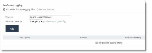
Control | Description |
Add a New Process Logging Filter | Displays the controls for adding a process level logging filter. |
Process | Select a process to include in the log from the drop-down list: •alarmd - Alarm control and management. •cifs - CIFS Optimization. •cmcfc - CMC automatic registration utility. •rgp - SCC connector, which handles SCC appliance communication. •rgpd - SCC client daemon, the connection manager. •cli - Command-line interface. •mgmtd - Device control and management, which directs the entire device management system. It handles message passing between various management daemons, managing system configuration and general application of system configuration on the hardware underneath through the Hardware Abstraction Layer Daemon (HALD). •http - HTTP optimization. •hald - Hardware Abstraction Layer Daemon, which handles access to the hardware. •notes - Lotus Notes optimization. •mapi - MAPI optimization. •nfs - NFS optimization. •pm - Process Manager, which handles launching of internal system daemons and keeps them up and running. •sched - Process Scheduler, which handles one-time scheduled events. •virtwrapperd - VSP VMWare interface. •vspd - VSP Watchdog. •statsd - Statistics Collector, which handles queries and storage of system statistics. •wdt - Watchdog Timer, the motherboard watchdog daemon. •webasd - Web Application Process, which handles the web user interface. •domain auth - Windows Domain Authentication. |
Minimum Severity | Select the minimum severity level for the log messages. The log contains all messages with this severity level or higher. Select one of these levels from the drop-down list: •Emergency - The system is unusable; action must be taken immediately. •Alert - Action must be taken immediately. •Critical - Conditions that affect the functionality of the SteelHead. •Error - Conditions that probably affect the functionality of the SteelHead. •Warning - Conditions that could affect the functionality of the SteelHead, such authentication failures. •Notice - Normal but significant conditions, such as a configuration change. •Info - Informational messages that provide general information about system operations. |
Add | Adds the filter to the list. The process now logs at the selected severity and higher level. |
Remove Selected | Select the check box next to the name and click Remove Selected to remove the filter. |
Control | Description |
Change Password | Specify this option to change the password. |
New Password | Specify a new password. |
Confirm New Password | Confirm the new password. |
Apply | Applies your settings to the running configuration. |
Control | Description |
Current Configuration: <configuration name> | View Running Config - Displays the running configuration settings in a new browser window. Save - Saves settings that have been applied to the running configuration. Revert - Reverts your settings to the running configuration. |
Save Current Configuration | Specify a new filename to save settings that have been applied to the running configuration as a new file, and then click Save As. |
Control | Description |
Import a New Configuration | Displays the controls for importing a new configuration. |
IP/Hostname | Specify the IP address or hostname of the SteelHead from which you want to import the configuration. |
Remote Admin Password | Specify the administrator password for the remote SteelHead. |
Remote Config Name | Specify the name of the configuration you want to import from the remote SteelHead. |
New Config Name | Specify a new, local configuration name. |
Import Shared Data Only | Takes a subset of the configuration settings from the imported configuration and combines them with the current configuration to create a new configuration. Import shared data is enabled by default. |
Import | When the Import Shared Data Only check box is selected, activates the imported configuration and makes it the current configuration. This is the default. When the Import Shared Data Only check box isn’t selected, adds the imported configuration to the Configuration list. It doesn’t become the active configuration until you select it from the list and click Activate. |
Remove Selected | Select the check box next to the name and click Remove Selected. |
To Change Active Configuration | Under Change Active Configuration, select the configuration to activate from the drop-down list and click Activate. |
Control | Description |
Authentication Methods | Specifies the authentication method. Select an authentication method from the drop-down list. The methods are listed in the order in which they occur. If authorization fails on the first method, the next method is attempted, and so on, until all of the methods have been attempted. |
For RADIUS/TACACS+, fallback only when servers are unavailable. | Specifies that the SteelHead falls back to a RADIUS or TACACS+ server only when all other servers don’t respond. This is the default setting. You must select this option if you want a safety account login on AAA servers that are unreachable. When this feature is disabled, the SteelHead doesn’t fall back to the RADIUS or TACACS+ servers. If it exhausts the other servers and doesn’t get a response, it returns a server failure. |
Safety Account | Creates a safety account so that admin/sys admin users can login to the SCC even if remote authentication servers are unreachable. A safety account increases security and conforms to Defense Information Systems Agency (DISA) requirements. Only the selected safety account will be allowed to login in cases where the AAA server isn’t reachable. (Only one user can be assigned to the safety account.) You can create a system administrator user in the Administrator > Security: User Permissions page. For details, see “Managing user permissions” on page 128. |
Safety Account User | Select the user from the drop-down list. |
Authorization Policy | Appears only for some Authentication Methods. Optionally, select one of these policies from the drop-down list: •Remote First - Check the remote server first for an authentication policy, and only check locally if the remote server doesn’t have one set. This is the default behavior. •Remote Only - Checks the remote server. •Local Only - Checks the local server. All remote users are mapped to the user specified. Any vendor attributes received by an authentication server are ignored. |
Default User | Select the default user from the drop-down box. |
Apply | Applies your settings to the running configuration. |
Control | Description |
Never | Select to require the current user to log in when the SCC opens. |
When logged in as admin | Select to log in as the admin user for the appliance when the SCC opens. Note: The registered user must have administrative privileges. |
When logged in as the appliance registered user | Select to log in when the SCC opens using the same name as the registered user to log in to the SCC. For this option to function properly, the SCC login must match the registered user login for the system. |
Control | Description |
These settings control the log in information used when the SCC for an individual appliance is accessed directly from the Dashboard of the SCC. These settings control how the URLs are generated for the appliances shown on the Dashboard. | |
Always use http | Select to always generate the appliance URL using the HTTP protocol. |
Always use https | Select to always generate the appliance URL using the HTTPS protocol. |
Use https if enabled, otherwise http | Select to generate the appliance URL automatically based on whether the appliance is SSL-enabled (HTTPS) or not (HTTP). |
Use the Fully-Qualified Domain Name provided by the appliance | Select to use the fully qualified domain name provided by the appliance. This is the default setting. If the FQDN isn’t obtainable, the registered address will be used. Note: The SCC resolves the FQDN to an IP. |
Use the IP Address/Hostname registered with the SCC | Select to use the IP Address/Hostname registered with the SCC. |
Control | Description |
Use Common Appliance Credentials | Displays the controls for the common administration login. When enabled, the Common Appliance Username/Password is used for all appliance connections. The appliance-specific username/password is ignored |
User Name | Enter the username. |
Password | Enter the password. |
Confirm Password | Confirm the password. |
Control | Description |
Enable/disable the certificate authority | Select the check box to enable certificate authority. - or - Clear the check box to disable certificate authority. |
Cipher bits | Select the key length from the drop-down list. The default value is 2048. |
Signing algorithm | Select the signing algorithm from the drop-down list. The default value is SHA256withRSA. |
Apply | Applies the settings to the running configuration. After you click Apply, the Certificate Authority tabs are displayed for viewing or replacing the certificate. |
Control | Description |
Details | Displays the certificate details. |
PEM | Displays the certificate in PEM format. |
Replace | Displays the controls for replace or generating a CA-Signed certificate. |
Import Existing Private Key and CA-Signed Public Certificate (One File in PEM format) | Select this option if the existing private key and CA-signed certificate are located in one file. The page expands displaying Private Key and CA-Signed Public Certificate controls for browsing to the key and certificate files or a text box for copying and pasting the key and certificate. |
Private Key | The private key is required regardless of whether you’re adding or updating. •Local File - Browse to the local file. •Text - Paste the content of the file. •Decryption Password - Specify the password used to decrypt, if necessary. •Change - Changes the settings. |
Import Existing Private Keys and CA-Signed Public Certificate (Two Files in PEM format) | Select this option if the existing private key and CA-signed certificate are located in two files. The page expands displaying Private Key and CA-Signed Public Certificate controls for browsing to the key and certificate files or text boxes for copying and pasting the keys and certificates. |
Private Key | A private key is optional for existing server configurations. •Private Key Local File - Browse to the local file containing the private key. •Private Key Text - Paste the private key text. |
CA-Signed Public Certificate | •LocalCert Text - Paste the content of the certificate text file. •File - Browse to the local file. •Decryption Password - Specify the password used to decrypt, if necessary. •Change - Changes the settings. |
Generate New Private Key and Self-Signed Public Certificate | Select this option to generate a new private key and self-signed public certificate. •Cipher Bits - Select the key length from the drop-down list. The default value is 2048. •Common Name - Specify the domain name of the server. •Organization Name - Specify the organization name (for example, the company). •Organization Unit Name - Specify the organization unit name (for example, the section or department). •Locality - Specify the city. •State (no abbreviations) - Specify the state. •Country (2-letter code) - Specify the country (2-letter code only). •Email Address - Specify the email address of the contact person. •Validity Period (Days) - Specify how many days the certificate is valid. •Change - Changes the settings. •Generate New Private Key and Certificate - Generates new private key and certificate. |
Control | Description |
Optional Local Name | Optionally, specify the name of the trusted CA store. |
Local File | Select this option and browse to the local file. |
Cert text | Select this option to copy and paste the certificate authority. |
Add | Adds the certificate authority to the trusted CA store. |
Management Console page | Feature (to configure or change this feature) | Required settings for read permission | Required settings for read/write permission |
Manage > Topology: Sites & Networks | Networks | Network Settings Read-Only | Network Settings read/write Policy Push read/write |
Sites | Network Settings Read-Only QoS/Path Selection Read-Only | Network Settings read/write Policy Push read/write QoS/Path Selection read/write | |
Manage > Applications: App Definitions | Applications | Network Settings Read-Only | Network Settings read/write Policy Push read/write |
Manage > Services: Quality of Service | Enable QoS | Network Settings Read-Only | Network Settings read/write QoS/Path Selection read/write Policy Push read/write |
Manage QoS Per Interface | Network Settings Read-Only | Network Settings read/write QoS/Path Selection read/write Policy Push read/write | |
QoS Profile | QoS/Path Selection Read-Only | QoS/Path Selection read/write Policy Push read/write | |
Manage > Services: QoS Profile Details | QoS Profile Name | QoS/Path Selection Read-Only | QoS/Path Selection read/write Policy Push read/write |
QoS Classes | QoS/Path Selection Read-Only | QoS/Path Selection read/write Policy Push read/write | |
QoS Rules | QoS/Path Selection Read-Only | Network Settings read/write QoS/Path Selection read/write Policy Push read/write | |
Manage > Services: Path Selection | Enable Path Selection | Network Settings Read-Only | Network Settings read/write Policy Push read/write |
Path Selection Rules | Network Settings Read-Only QoS/Path Selection Read-Only | Network Settings read/write QoS/Path Selection read/write Policy Push read/write | |
Uplink Status | Network Settings Read-Only QoS/Path Selection Read-Only Reports read/write | — | |
Manage > Topology: Clusters | Interceptor Clusters | Network Settings Read-Only | Interceptor/Cluster Settings read/write Policy Push read/write |
Page | Description |
SCC Settings | Manages the SCC features: for example, host settings, network settings and reports. |
AAA Configurations | Authenticates and authorizes SCC users. |
Page | Description |
Global | Configures Global group settings. |
<group> | Configures the <group> settings. |
Control | Description |
admin/monitor | Click the right arrow to modify the admin and monitor accounts. |
Clear Login Failure Details | Clears the account log in failure details and closes the fields for changing the password. |
Change Password | Enables password protection. Password protection is an account control feature that allows you to select a password policy for more security. When you enable account control on the Administration > Security: Password Policy page, a user must use a password. When a user has a null password to start with, the administrator can still set the user password with account control enabled. However, once the user or administrator changes the password, it can’t be reset to null as long as account control is enabled. •Password - Specify a password in the text box. •Password Confirm - Retype the new administrator password. |
Enable Account | Activates the account. Clear the check box to disable the administrator or monitor account. When enabled, you may make the account the default user for RADIUS and TACACS+ authorization. You may only designate one account as the default user. Once enabled, the default user account may not be disabled or removed. The Accounts table displays the account as permanent. |
Allow Policy Push for Non-Admin Connected Appliances | Enables administrator users to perform configuration pushes to appliances connected with nonadministrator role-based management users, provided the nonadministrator role-based management users have read/write privileges on the appliance. |
Apply | Applies your changes to the running configuration. |
Control | Description |
Add a New User | Displays the controls for adding a new user. |
Account Name | Specify a name for the role-based account. |
Password | Specify a password in the text box, and then retype the password for confirmation. |
Enable Account | Select the check box to enable the new account. |
Make this The AAA Default User (for RADIUS and TACACS+ logins) | Select to make the user the default AAA user to provide strict AAA access for RADIUS and TACACS+ logins. |
Policy Visibility Restricted | Restricts viewing, editing, and deleting of policies in groups for which RBM users don’t have access. •Users with deny access to a group can’t view the policies associated with that group from the Manage->Policy page. •Users with read-only access to a group can only view the policies associated with that group from the Manage > Policy page. Read-only users can’t edit policies. •Users can‘t view or attach a policy to an accessible group if that policy is already attached to a group for which the user doesn’t have read/write permission. Users can still view and edit the policies associated with the groups for which they have access. Users with only read/write access to a group can view and edit the policies associated for that group. |
User Roles | Create system administrator or role-based management accounts for users. •Administrator - Creates a system administrator account for the user. This is an administrator account with full access to configurations and reports on this appliance. This account can also be used to create, edit, and remove user accounts. Create a system administrator account to increase security and to conform to Defense Information Systems Agency (DISA) requirements. In cases where an AAA server isn’t reachable and the admin user or system administrator isn’t able to login, you can create a safety account in the Administrator > Security: General Settings page. For details, see “Configuring general security settings” on page 121. •RBM User - Select to create a role based management user and apply permissions for each role below. –CMC (SCC) Settings - Manages the SCC features: for example, host settings, network settings and reports. –AAA Configurations - Authenticates and authorizes SCC users. |
Groups | •Global - Configures Global group permissions. |
Appliance Management | Controls appliance upgrades, policy pushes, and so forth. •Appliance Upgrade - Configures permissions for appliance upgrade. •File Transfer - Configures permissions for file transfers on managed appliances. •Non Admin Connected Appliance's Policy - Enables administrator users to perform configuration pushes to appliances connected with nonadministrator role-based management users, provided the nonadministrator role-based management users have read/write privileges on the appliance. If the push fails, verify if the nonadministrator role-based management user has the required permissions to modify the page that’s being pushed on the appliance and on the SCC: for example, to push QoS changes the user must also have read/write permissions for Role Based Accounts > Appliance Management Roles > Optimization Settings > Qos/Path Selection. •SteelHead Backup - Configures permissions for SteelHead backups on managed appliances. •Operation Status - Configures permissions for operation status on managed appliances. •CLI Commands - Configures permissions for CLI commands to managed appliances. |
Appliance Settings | Manage appliance permissions, such as cluster configuration, host settings, network settings, and so forth. •Interceptor/Cluster Settings - Configures permissions for Interceptor clusters. You must also include the Policy Push role. •General Settings - Configures permissions for general system settings. •Network Settings - Configures permissions for topology definitions, site and network definitions, application definitions, host interface settings, network interface, DNS cache, hardware assist rules, host labels, and port labels. You must include this role for users configuring path selection or enforcing QoS policies in addition to the QoS and Path Selection roles. •Reports - Configures permissions for reports. •Basic Diagnostics - Configures permissions for basic diagnostic reports. •SteelFusion Branch Storage Device Service - Configures permissions for SteelFusion Branch. •TCP Dumps - Configures permissions for TCP Dump. |
Appliance AAA Configuration | Appliance security permissions. •Security Settings - Configures security permissions, including RADIUS and TACACS authentication settings and the secure vault password. |
Optimization Settings | Manage appliance optimization setup. •SteelHead In-Path Rules - Configures permissions for TCP traffic for optimization and optimizing traffic with in-path rules. This role includes WAN visibility to preserve TCP/IP address or port information. For details about WAN visibility, see the SteelHead Deployment Guide •QoS/Path Selection - Configures permissions for QoS policies and path selection. You must also include the Network Settings role for QoS and path selection. |
Application Optimization Policies | Configure optimization permissions for different applications. •Optimization Service - Configures permissions for alarms, performance features, SkipWare, HS-TCP, and TCP optimization. •CIFS Optimization - Configures permissions for CIFS optimization settings (including SMB signing) and Overlapping Open optimization. •HTTP Optimization - Configures permissions for enhanced HTTP optimization: URL learning, parse and prefetch, object prefetch table, keepalive, insert cookie, file extensions to prefetch, and the ability to set up HTTP optimization for a specific server subnet. •Oracle Forms Optimization - Configures permissions for Oracle E-business application content and forms applications. •MAPI Optimization - Configures permissions for MAPI and sets Exchange and NSPI ports. •SQL Optimization - Configures permissions for SQL optimization. •NFS Optimization - Configures permissions for NFS optimization. •Notes Optimization - Configures permissions for Lotus Notes optimization. •Citrix Optimization - Configures permissions for Citrix optimization. •SSL Optimization - Configures permissions for SSL support and the secure inner channel. •Replication Optimization - Configures permissions for the SRDF/A, FCIP, and SnapMirror storage optimization modules. •Domain Authentication - Configures permissions for joining a Windows domain and configuring Windows domain authentication. |
Branch Services | Branch services permissions: •Proxy File Service (PFS) - Configures permissions for a virtualized environment on the client SteelHead. The functionality can include third-party packages such as a firewall security package, a streaming video server, or a package that provides core networking services (for example, DNS and DHCP). This role includes permission to install VMware tools and add subnet side rules. For details, see the RSP User Guide. •RSP/VSP - Configures permissions for Riverbed Services Platform (RSP) and Virtual Services Platform (VSP). |
Add | Adds your settings to the system. |
Remove Selected Accounts | Select the check box next to the name and click Remove Selected. |
Control | Description |
Login Attempts Before Lockout | Specify the maximum number of unsuccessful login attempts before temporarily blocking user access to the SteelHead appliance. The user is prevented from further login attempts when the number is exceeded. The default for the strong security template is 3. The lockout expires after the amount of time specified in Timeout for User Login After Lockout elapses. |
Timeout for User Login After Lockout | Specify the amount of time, in seconds, that must elapse before a user can attempt to log in after an account lockout due to unsuccessful login attempts. The default for the strong security template is 300. |
Days Before Password Expires | Specify the number of days the current password remains in effect. The default for the strong security template is 60. To set the password expiration to 24 hours, specify 0. To set the password expiration to 48 hours, specify 1. Leave blank to turn off password expiration. |
Days to Warn User of an Expiring Password | Specify the number of days the user is warned before the password expires. The default for the strong security template is 7. |
Days to Keep Account Active After Password Expires | Specify the number of days the account remains active after the password expires. The default for the strong security template is 305. When the time elapses, RiOS locks the account permanently, preventing any further logins. |
Days Between Password Changes | Specify the minimum number of days before which passwords can’t be changed. |
Minimum Interval for Password Reuse | Specify the number of password changes allowed before a password can be reused. The default for the strong security template is 5. |
Enable Temporary Password Setting | Specify a temporary password to improve security and to conform to Defense Information Systems Agency (DISA) requirements. A temporary password can be enabled only if Account Control is enabled. If a temporary password is set, then the password set by Admin/Sys Admin for the new user shall expire on the first log in of the new user. A password expired page will appear for new users after the first login. If a temporary password is set and the Admin/Sys Admin resets the password for the existing user, the password will expire at the first log in after the reset. A password expired page will appear for existing users upon the first login after a password reset. |
Control | Description |
Minimum Password Length | Specify the minimum password length. The default for the strong security template is 14 alphanumeric characters. |
Minimum Uppercase Characters | Specify the minimum number of uppercase characters required in a password. The default for the strong security template is 1. |
Minimum Lowercase Characters | Specify the minimum number of lowercase characters required in a password. The default for the strong security template is 1. |
Minimum Numerical Characters | Specify the minimum number of numerical characters required in a password. The default for the strong security template is 1. |
Minimum Special Characters | Specify the minimum number of special characters required in a password. The default for the strong security template is 1. |
Minimum Character Differences Between Passwords | Specify the minimum number of characters that must be changed between the old and new password. The default for the strong security template is 4. |
Maximum Consecutively Repeating Characters | Specify the maximum number of times a character can occur consecutively. |
Prevent Dictionary Words | Select to prevent the use of any word that’s found in a dictionary as a password. By default, this control is enabled. |
Apply | Applies your settings to the running configuration. |
Control | Description |
Set a Global Default Key | Enables a global server key for the RADIUS server. |
Global Key | Specify the global server key. |
Confirm Global Key | Confirm the global server key. |
Timeout | Specify the time-out period in seconds (1 to 60). The default value is 3. |
Retries | Specify the number of times you want to allow the user to retry authentication. The default value is 1. |
Apply | Applies your settings to the running configuration. |
Control | Description |
Add a RADIUS Server | Displays the controls to add a RADIUS server. |
Hostname or IP Address | Specify the hostname or server IP address. The IP address can be either IPv4 or IPv6. For IPv6 specify an IP address using this format: eight 16-bit hexadecimal strings separated by colons, 128-bits. For example: 2001:38dc:0052:0000:0000:e9a4:00c5:6282 You don’t need to include leading zeros. For example: 2001:38dc:52:0:0:e9a4:c5:6282 You can replace consecutive zero strings with double colons (::). For example: 2001:38dc:52::e9a4:c5:6282 |
Authentication Port | Specify the port for the server. |
Authentication Type | Select one of these authentication types: •PAP - Password Authentication Protocol (PAP), which validates users before allowing them access to the RADIUS server resources. PAP is the most flexible protocol but is less secure than CHAP. •CHAP - Challenge-Handshake Authentication Protocol (CHAP), which provides better security than PAP. CHAP validates the identity of remote clients by periodically verifying the identity of the client using a three-way handshake. This validation happens at the time of establishing the initial link and might happen again at any time. CHAP bases verification on a user password and transmits an MD5 sum of the password from the client to the server. •MS-CHAPv2 - MS-CHAP is the Microsoft version of CHAP. MS-CHAPv2 is a more secure authentication protocol than PAP or CHAP. (CHAP uses MD5 while MS-CHAPv2 uses MD4 and SHA-1 which might not be FIPS compliant.) |
Override the Global Default Key | Overrides the global server key for the server. |
Server Key - Specify the override server key. | |
Confirm Server Key - Confirm the override server key. | |
Timeout | Specify the time-out period in seconds (1 to 60). The default value is 3. |
Retries | Specify the number of times you want to allow the user to retry authentication. Valid values are from 0 to 5. The default value is 1. |
Enabled | Enables the new server. |
Add | Adds the RADIUS server to the list. |
Remove Selected | Select the check box next to the name and click Remove Selected. |
Control | Description |
Set a Global Default Key | Enables a global server key for the server. |
Global Key | Specify the global server key. |
Confirm Global Key | Confirms the global server key. |
Timeout | Specify the time-out period in seconds (1 to 60). The default value is 3. |
Retries | Specify the number of times you want to allow the user to retry authentication. Valid values are from 0 to 5. The default is 1. |
Apply | Applies your settings to the running configuration. |
Control | Description |
Add a TACACS+ Server | Displays the controls for adding a TACACS+ server. |
Hostname or IP Address | Specify the hostname or server IP address. |
Authentication Port | Specify the port for the server. The default value is 49. |
Authentication Type | Select either PAP or ASCII as the authentication type. The default value is PAP. |
Override the Global Default Key | Specify this option to override the global server key for the server. |
Server Key | Specify the override server key. |
Confirm Server Key | Confirm the override server key. |
Timeout | Specify the time-out period in seconds (1 to 60). The default is 3. |
Retries | Specify the number of times you want to allow the user to retry authentication. Valid values are from 0 to 5. The default is 1. |
Enabled | Enables the new server. |
Add | Adds the TACACS+ server to the list. |
Remove Selected | Select the check box next to the name and click Remove Selected. |
Control | Description |
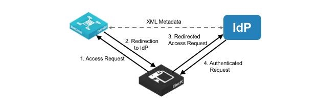
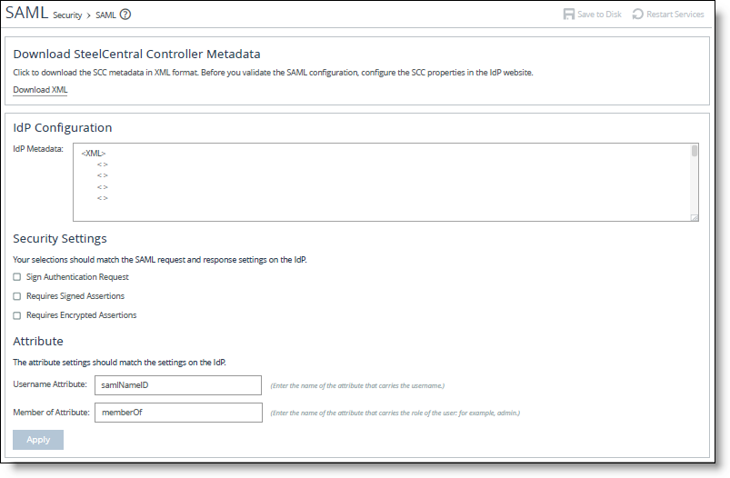
IdP Metadata | Paste the IdP metadata you copied or received from the IdP website. |
Security Settings | Sign Authentication Request - Select this option to have SCC sign the SAML authentication request sent to the identity provider. Signing the initial login request sent by SCC allows the identity provider to verify that all login requests originate from a trusted service provider. |
Requires Signed Assertions - Select if SAML assertions must be signed. Some SAML configurations require signed assertions to improve security. | |
Requires Encrypted Assertions - Select this option to indicate to the SAML identity provider that SCC requires encrypted SAML assertion responses. When this option is selected, the identity provider encrypts the assertion section of the SAML responses. Even though all SAML traffic to and from SCC is already encrypted by the use of HTTPS, this option adds another layer of encryption. | |
Attribute | User Name Attribute - Enter the name of the IdP variable that carries the username of the user. The user name attribute is mandatory and must be sent by your identify provider in the SAML response to align the login with a configured SteelHead account. Default value is samlNameId. |
Member of Attribute - Enter the name of the IdP variable that carries the role of the user. Default value is memberOf. |
Control | Description |
Password | Specify a password and click Unlock Secure Vault. Initially the secure vault is keyed with a default password known only to the RiOS software. This enables the system to automatically unlock the vault during system start up. You can change the password, but the secure vault doesn’t automatically unlock on start up. To optimize SSL connections or to use RiOS data store encryption, you must unlock the secure vault. |
Unlock Secure Vault | Unlocks the vault. |
Control | Description |
Current Password | Specify the current password. If you’re changing the default password that ships with the product, leave the text box blank. |
New Password | Specify a new password for the secure vault. |
New Password Confirm | Retype the new password for the secure vault. |
Change Password | Changes the password to the new value. |
Control | Description |
Enable Management ACL | Select this check box to enable the management ACL. |
Apply | Applies your settings to the running configuration. |
Control | Description |
Add a New Rule | Displays the controls for adding a new ACL rule. |
Action | Select one of these rule types from the drop-down list: •Allow - Allows a matching packet access to the SteelHead. This is the default action. •Deny - Denies access to any matching packets. |
Service | Optionally, select Specify Protocol, or HTTP, HTTPS, SOAP, SNMP, SSH, Telnet. When specified, the Destination Port is dimmed. |
Protocol | (Appears only when Service is set to Specify Protocol.) Optionally, select All, TCP, UDP, or ICMP from the drop-down list. The default setting is All. When set to All or ICMP, the Service and Destination Ports are dimmed. |
Source Network | Optionally, specify the source subnet of the inbound packet: for example, 1.2.3.0/24. |
Destination Port | Optionally, specify the destination port of the inbound packet, either a single port value or a port range of port1-port2, where port1 must be less than port2. Leave it blank to specify all ports. |
Interface | Optionally, select an interface name from the drop-down list. Select All to specify all interfaces. |
Description | Optionally, describe the rule to facilitate administration. |
Rule Number | Optionally, select a rule number from the drop-down list. By default, the rule goes to the end of the table (just above the default rule). SteelHeads evaluate rules in numerical order starting with rule 1. If the conditions set in the rule match, then the rule is applied, and the system moves on to the next packet. If the conditions set in the rule don’t match, the system consults the next rule. For example, if the conditions of rule 1 don’t match, rule 2 is consulted. If rule 2 matches the conditions, it is applied, and no further rules are consulted. Note: The default rule, Allow, which allows all remaining traffic from everywhere that hasn’t been selected by another rule, can’t be removed and is always listed last. |
Log Packets | Tracks denied packets in the log. By default, packet logging is enabled. |
Add | Adds the rule to the list. The Management Console redisplays the Rules table and applies your modifications to the running configuration, which is stored in memory. |
Remove Selected | Select the check box next to the name and click Remove Selected. |
Move Selected | Moves the selected rules. Click the > next to the desired rule position; the rule moves to the new position. |
Control | Description |
Default Web Login ID | Specify the username that appears in the authentication page. The default value is admin. |
Web Inactivity Timeout | Specify the number of idle minutes before time-out. The default value is 15. A value of 0 disables time-out. |
Allow Session Timeouts When Viewing Auto-Refreshing Pages | By default, session time-out is enabled, which stops the automatic updating of the report pages when the session times out. Clear the Allow box to disable the session time-out, remain logged in indefinitely, and automatically refresh the report pages. Note: Disabling this feature poses a security risk. |
Apply | Applies your settings to the running configuration. |
Control | Description |
Issued To/Issued By | Common Name - Specifies the common name of the certificate authority. |
Email - Specifies the organization email. | |
Organization - Specifies the organization name (for example, the company). | |
Locality - Specifies the city. | |
State - Specifies the state. | |
Country - Specifies the country. | |
Validity | Issued On - Specifies the date the certificate was issued. |
Expires On - Specifies the date the certificate expires. | |
Fingerprint | Specifies the SSL fingerprint. |
Key | Type - Specifies the key type. |
Size - Specifies the sizes in bytes. |
Control | Description |
Import Certificate and Private Key | Imports the certificate and key. The page displays controls for browsing to and uploading the certificate and key files. You can also use the text box to copy and paste a PEM file. The private key is required regardless of whether you’re adding or updating the certificate. |
Certificate | Select the action. •Upload - Browse to the local file in PKCS-12, PEM, or DER formats. •Paste it here (PEM) - Copy and then paste the contents of a PEM file. |
Private Key | Select the private key origin. •The Private Key is in a separate file (see below) - You can either upload it or copy and paste it. •This file includes the Certificate and Private Key •The Private Key for this Certificate was created with a CSR generated on this appliance. |
Separate Private Key | Select the action: •Upload (PEM or DER formats) - Browse to the local file in PEM or DER formats. •Paste it here (PEM only) - Paste the contents of a PEM file. |
Decryption Password | Specify the decryption password, if necessary. Passwords are required for PKCS-12 files, optional for PEM files, and never needed for DER files. |
Import Certificate and Key | Imports the certificate and key. |
Generate Self-Signed Certificate and New Private Key | Select to generate a new private key and self-signed public certificate. |
Organization Name - Specify the organization name (for example, the company). | |
Organization Unit Name - Specify the organization unit name (for example, the section or department). | |
Locality - Specify the city. | |
State (no abbreviations) - Specify the state. | |
Country (2-letter code) - Specify the country (2-letter code only). | |
Email Address - Specify the email address of the contact person. | |
Validity Period (Days) - Specify how many days the certificate is valid. The default value is 730. | |
Private Key | Cipher Bits - Select the key length from the drop-down list. The default value is 1024. |
Generate Certificate and Key | Generates a private key and CSR. |
Apply | Applies your settings to the running configuration. |
Control | Description |
Common Name (required) | Specify the common name (hostname) of the peer. |
Organization Name | Specify the organization name (for example, the company). |
Organization Unit Name | Specify the organization unit name (for example, the section or department). |
Locality | Specify the city. |
State | Specify the state. Don’t abbreviate. |
Country (2-letter code) | Specify the country (2-letter code only). |
Email Address | Specify the email address of the contact person. |
Generate CSR | Generates the Certificate Signing Request. |
Control | Description |
Add Access Code | Displays the controls for adding an access code. |
Description of Use | Type a description, such as the hostname or IP address of the appliance you’re using. |
Generate New Access Code | Generates the new access code. Click Add to add the code to the running configuration. The access code is displayed in the table. |
Import New Access Code | Copy and paste an existing access code in the text box. |
Add | Adds the access code to the running configuration. The access code is displayed in the table. |
Control | Description |
Protocol | Select from the drop-down list the file server protocol for the backup server for storing or retrieving the backup: •CIFS - Specify a domain name, username, and password. •NFS - Specify the hostname or IP address and the remote path. •SSH - Specify a username and password or you can configure a backup using an RSA public key that doesn’t require password authentication. Note: If you back up to an NFS or SSH server and the same backup location is subsequently exposed via CIFS, the backup can fail. If the backups and restores are slow, use CIFS and NFS. |
Hostname or IP Address | Specify the hostname or IP address for the backup server. |
Remote Path | Specify the directory path on the backup server for the backup file. For example, for CIFS: \<sharename>\<directory>\<directory> or <sharename>/<directory> For example, for NFS: /<mount>/<point>/<directory> For example, for SSH: /<directory>/<directory> Note: The directory must already exist on the backup server. |
CIFS Domain (CIFS only) | Specify the CIFS domain. Tip: If the username corresponds to a local account (as opposed to a domain account), this field should contain the NETBIOS name of the backup server. |
User Name | Specify a valid username for CIFS or SSH access. |
Password | Supply a valid password for CIFS or SSH access. |
Password Confirm | Confirm the password for CIFS or SSH access. |
Time Limit for Statistics Backup | Specify the time limit, in minutes. The default value is 0. |
Disk Space Limit | Specify the disk space limit, in megabytes. The default value is 0. |
Total Capacity | Select the drop-down error to view more information. •Available Space - Displays the available space, such as: Available to SCC Data and Reserved for Other SCC. •Used Space - Displays the used space, such as: Used by SCC Configuration Snapshots, Used by Appliance Snapshots, and Used by Statistics. •Used by Other Data - Displays the used by other data information. |
Control | Description |
Protocol | Select SSH from the drop-down list. Note: If you back up to an NFS or SSH server and the same backup location is subsequently exposed via CIFS, the backup can fail. |
Hostname or IP Address | Specify the hostname or IP address for the backup server. |
Remote Path | Specify the directory path on the backup server for the backup file. For example, for SSH: /<directory>/<directory> Note: The directory must already exist on the backup server. |
User Name | Specify the username. |
SSH Authentication Type | Select Public Key and click Generate Key to generate the public key. The public key is generated in the Public Key text box. |
Public Key | After you click Generate Key, the key appears in the text box. Copy the public key to the user’s target machine: for example: /u/administrator/.ssh/authorized_keys |
Generate Key | Generates the public key in the Public Key text box. |
Time Limit for Statistics Backup | Specify the time limit, in minutes. The default value is 0. |
Disk Space Limit | Specify the disk space limit, in megabytes. The default value is 0. |
Total Capacity | Select the drop-down error to view more information. •Available Space - Displays the available space, such as: Available to SCC Data and Reserved for Other SCC. •Used Space - Displays the used space, such as: Used by SCC Configuration Snapshots, Used by Appliance Snapshots, and Used by Statistics. •Used by Other Data - Displays the used by other data information. |
Control | Description |
Schedule SCC Configuration Backup | Enables the backup of appliance configuration data. Complete these settings: •Start at - Specify the start using this format: yyyy/mm/dd hh:mm:ss •Repeat every - Specify the number of days the SCC configuration backup operation should be repeated. •Maximum SCC Snapshots Retained - Specify the maximum number of SCC snapshots. |
Schedule Appliance Snapshots Backup | Enables the backup of appliance snapshots data. You should perform a full backup before you can schedule appliance snapshot backup. Complete these settings: •Start at - Specify the start date using this format: yyyy/mm/dd hh:mm:ss •Repeat every - Specify the number of days for that the SCC snapshot backup operation should be repeated. |
Schedule Statistics Backup | Enables the backup of appliance statistic data. Statistics backups are incremental. Complete these settings: •Start at - Specify the start date using this format: yyyy/mm/dd hh:mm:ss •Repeat every - Specify the number of days for that the statistics backup operation should be repeated. |
Apply | Applies your changes to the running configuration. |
Operation | Description |
Backup SCC Configuration | Performs a backup of the current SCC configurations. •New Snapshot Name - Specify the new snapshot name in the text box. |
Restore SCC Snapshot | Restores the specified SCC snapshot. •Restore Snapshot Name - Select the name from the drop-down list. •Restore Secure Vault - Select to enable the restore secure vault option. •Vault Password - Specify the vault password. Leave blank if using the factory password. •Restore Primary and Aux network interfaces - Select to restore primary and auxiliary network interfaces. |
Remove SCC Snapshot | Removes the specified SCC snapshot. •Remove Snapshot Name - Select the snapshot name from the drop-down list. |
Backup Appliance Snapshots | Performs a backup of the current appliance snapshot. •Exclude nightly snapshots older than <number> Days - Specify the number of days to be excluded. The default is 0. |
Restore Appliance Snapshot | Restores the specified appliance snapshot. |
Backup Statistics | Performs a backup of the current SCC statistics. |
Restore Statistics | Restores the latest statistics backup. |
Control | Description |
Start Time | Specify the start time for the job. Use this format: hh:mm:ss The duration of Maintenance Window should be at least three hours. |
End Time | Specify the end time for the job. Use this format: hh:mm:ss |
Apply | Applies your changes to the running configuration. |
Control | Description |
Name | Specify a name for the job. |
Comment | Specify a comment. |
Interval (seconds) | Specify the number of seconds between job recurrences. Specify 0 to run the job one-time only. |
Executes on | Specify the start time and end time using the format yyyy/mm/dd hh:mm:ss |
Enable/Disable Job | Select the check box to enable the job, clear the check box to disable the job. |
Apply Changes | Applies the changes to the current configuration. |
Cancel/Remove This Job | Cancels and removes the job. |
Execute Now | Runs the job. |
Remove Selected Jobs | Select the check box next to the name and click Remove Selected Jobs. |
Control | Description |
Add a New License | Displays the controls to add a new license. |
Licenses Text Box | Copy and paste the license key provided by Riverbed Support or Sales into the text box. Separate multiple license keys with a space, Tab, or Enter. |
Add | Adds the license. |
Fetch Updates Now | Contacts the Riverbed license portal and downloads all applicable licenses for the SteelHead. |
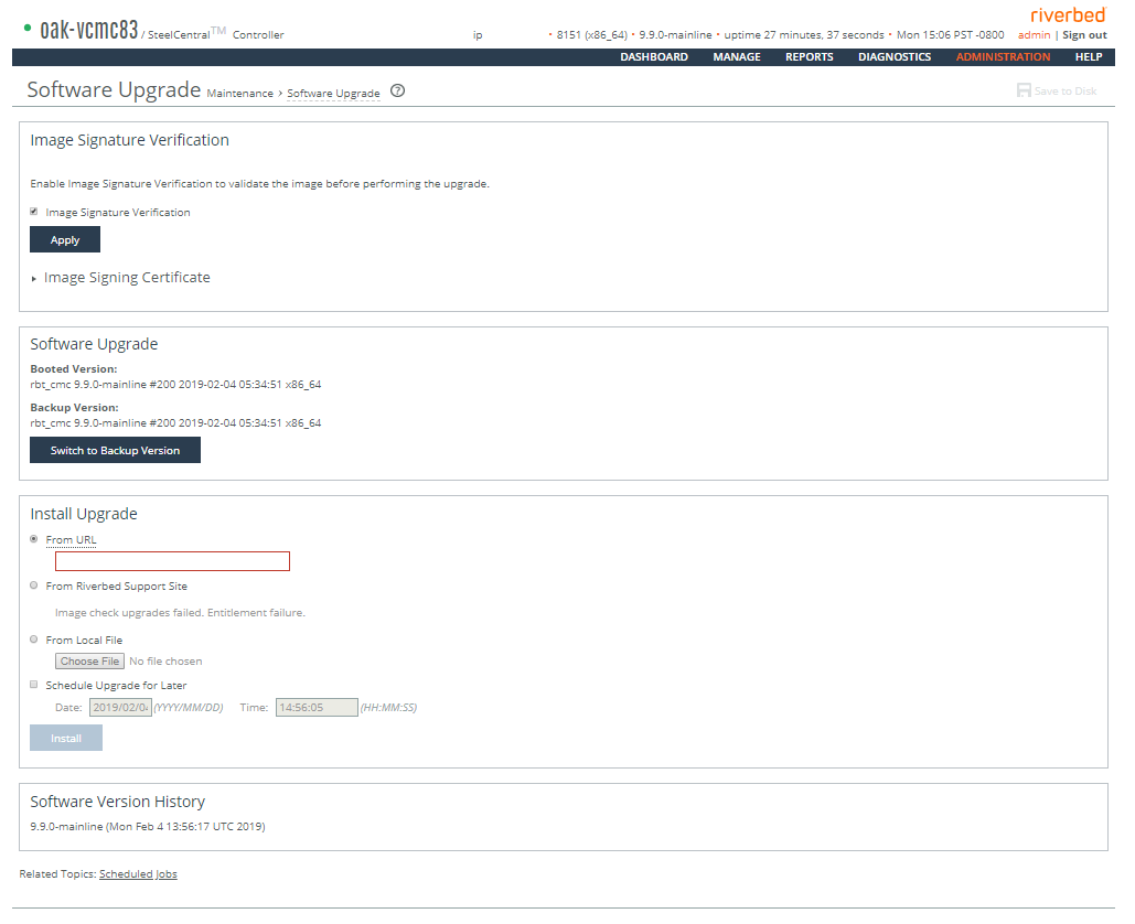
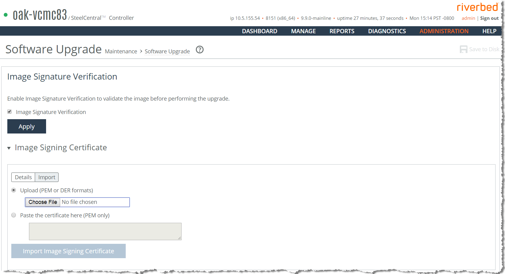
Control | Description |
Switch to Backup Version | Switches to the backup version on the next reboot. |
Cancel | Cancels the software version switch on the next reboot. |
Control | Description |
From URL | Select this option and specify the URL. Use one of these formats: http://host/path/to/file https://host/path/to/file ftp://user:password@host/path/to/file scp://user:password@host/path/to/file |
From Riverbed Support Site | Click this option and select the target release number from the drop-down list. The system uploads and installs the new image immediately after you click Install. To upload and install the image later, schedule another date or time before you click Install. |
From Local File | Select this option and specify the path, or click Browse to go to the local file directory. If you specify a file to upload in the Local File text box, the image is uploaded immediately; however the image is installed and the system is rebooted at the time you specify. |
Schedule Upgrade for Later | Schedules the upgrade process. Specify the date and time to run the upgrade: yyyy/mm/dd hh:mm:ss |
Install | Click to install the software upgrade on your system, unless you schedule it for later. The software image can be quite large; uploading the image to the appliance and installing it can take a few minutes. Downloading a delta image directly from the Riverbed Support site is faster because the downloaded image includes only the incremental changes. As the upgrade progresses, status messages appear. After the installation is complete, the system reminds you to reboot the appliance to switch to the new version of the software. |
Cancel | Cancels your changes. |