Managing Your Network
This chapter describes how to use the SCC to manage remote Riverbed appliances. This chapter includes these sections:
Managing sites and networks
You configure your network topology, that is networks, sites, and uplinks in the Sites & Networks page. This sections includes these topics:
Previously, the management paradigm for the SCC was appliances and appliance groups. SCC 9.0 and later introduced a new paradigm for hybrid networking made up of sites, networks, uplinks, and regions.
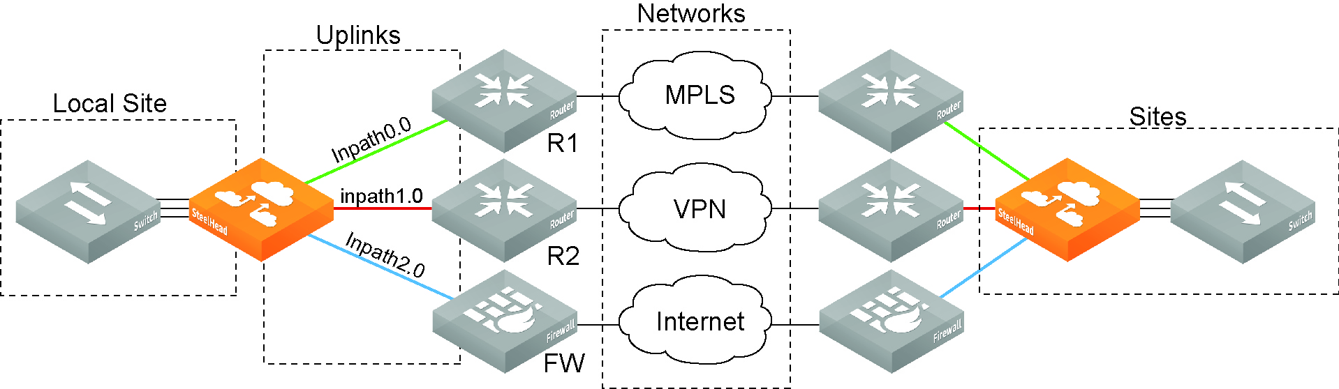
Hybrid network architecture combines private assets such as MPLS-based WAN networks with public services such as the Internet. RiOS provides application-level Quality of Service (QoS) and WAN path selection to control network consumption and prioritize critical and latency sensitive applications, while minimizing use by noncritical applications.
RiOS 9.0 and later provide the ability to configure a network topology and define applications policies based on business requirements. These two features provide the reusable building blocks that form the basis for configuring the features in a hybrid network: QoS, path selection, secure transport, and web proxy.
Defining a topology made up of sites, uplinks, networks, and regions is essential for configuring and managing hybrid features, such as QoS, path selection, secure transport, application statistics, and web proxy.
You define your network topology and application policies once and then reuse them as needed. The topology provides the network point-of-view to all other possible sites, including the network of the remote site and a remotely ping-able IP address.
You create a network topology to provide the building blocks for path selection, QoS, secure transport, application statistics, and web proxy. For example, SCC uses the topology definition to:
•share the remote site information between peers.
•determine possible remote paths for path selection.
•precompute the estimated end-to-end bandwidth for QoS, based on the remote uplinks.
A network topology includes these WAN topology properties:
•Networks - The networks represent the WAN clouds that sites and site types use to communicate to each other using Primary MPLS, VSAT, or the Internet. Basically, a network connects two uplinks between two sites. The SCC creates two nonsecure networks: MPLS and Internet. You can create additional secure and nonsecured networks or rename the precreated networks based on your topology requirements. You can also configure the Max Backoff Interval for a network to improve path selection performance. If there is no traffic at a site, the Max Backoff Interval default value of 1800 seconds determines how often that uplink is probed. Networks are important for path selection and secure transport. For details, see
“Defining networks” on page 178. •Sites - Define the discrete physical locations of Riverbed devices such as SteelHeads in the network (for example, a branch office or data center) so that you can more easily configure and manage your network. A site is a logical grouping of subnets and represents the physical and logical topology of a site type. You classify traffic for each site using IP addresses. Sites are linked to one or more networks. The local sites use the WAN in the network definition to connect to the other sites. The default site is a catch-all site that’s the only site needed to backhaul traffic. Sites are used with the path selection, QoS, and secure transport features. For details, see
“Defining sites” on page 182. •Site Types - Groups one or more sites based on common attributes, such as business function and size. Riverbed automatically creates the basic site types: Data Center, Branch, and Headquarters. Site types are the building blocks for QoS profiles and pushing 9.0 and later features to SteelHeads. For details, see
“Defining site types” on page 191. •Uplinks - Define the last network segment connecting the local site to a network. You define carrier-assigned characteristics to an uplink: for example, the upload and download bandwidth and latency. An uplink must be directly (L2) reachable by at least one SteelHead or Interceptor in the local network. An uplink doesn’t need to be a physical in-path connection. Path selection uses only local uplinks. SteelHeads deployed in hybrid networks send ICMP probes on uplinks to establish contact with the appliances in the network. This uplink probing frequency can affect the scaling and performance of hybrid networks. Path selection rule-aware probing improves deployment scalability of hybrid networking. For details, see
“Defining uplinks” on page 201. •Uplink Types - An uplink type is a name for similar functioning uplinks. On the SCC, uplink types can be used across multiple sites and path selection rules can be created using these names. The name must be unique at a site (but it can be same across different sites) so that the system can detect which path selection rule uses which uplinks. Because path selection rules are global on the SCC, you’re restricted to eight uplink types. Uplink types are the building blocks for path selection. For example, you can label uplink types as primary, secondary, and tertiary based on the path selection preference. The uplink type can be based on the type of interface or network resource, such as Verizon or global resource of uplink abstraction that’s tied to a network. On the SteelHead, this field is called the
Uplink Name; on the SCC it is the
Uplink Type. For details, see
“Defining uplink types” on page 206. •Regions - Groups of sites based on a geographic location, such as North America, Europe, and so on. Regions are particularly important in reporting. Regions help you to troubleshoot network issues. For details, see
“Defining site regions” on page 192. Network topology
How is a site different from an appliance?
A site completes the topology by informing the SteelHead of what subnets reside at that location and what SteelHead is associated with them. When you register a SteelHead for the first time in the SCC it is known as an appliance. After your appliances are registered in the SCC, you create a site and select the appliance to be a part of the site. A site may or may not contain a SteelHeads. You should add all remote sites in your network even if there is no SteelHead associated with them.
If you have to manage legacy QoS and path selection configuration settings, this is an old policy push as opposed to the new hybrid policy push. If you have a mixed network where you’re managing legacy QoS and path selection settings and new ones, you will have to maintain two sets of configuration settings. You can still add SteelHeads to a site even though they’re not receiving new hybrid configuration settings but for the new hybrid features in 9.0 and later, the sites must be configured with those SteelHeads.
Before you begin
Gather the necessary information for your network topology:
•Gather existing appliance group names and the appliance information (such as IP address and serial number) that belong to them. Often, existing appliance groups correspond to a particular location—these appliances populate your sites in your network topology.
•Determine which appliances and subnets are associated with which sites in your network. Sites are essential to managing QoS, path selection, secure transport, application statistics, and web proxy.
•Create a network deployment diagram to help you identify networks, sites, and uplinks.
Defining networks
You define networks in the Sites & Networks page. On the Sites & Networks page you enable a specific network to be securable, that is, to encrypt traffic for secure transport. You can only define secure networks on the SCC; you can’t define secure networks on the SteelHead.
Networks represent the WAN clouds that sites and site types use to communicate to each other using Primary MPLS, VSAT, or the Internet. Essentially, a network connects two uplinks between two sites.
Networks are very important for path selection and secure transport. A secure network is specifically used for the secure transport. The SCC creates two nonsecure networks: MPLS and Internet. You can create additional secure and nonsecured networks or rename the precreated networks based on your topology requirements.
For secure transport, you must specify that a network is securable to ensure that the network is part of the secure transport group. A secure transport group is a set of SteelHeads that share the same cryptographic keys and have connectivity to each other. Any member of the secure transport group can create a tunnel to any other member of the same group instantaneously, without delay. The traffic doesn’t incur any added latency waiting for the tunnels to establish. For detailed information about configuring secure transport, see “Managing secure transport” on page 274.
You can specify a secure transport concentrator if you don’t want to overload your SteelHead in the demilitarized zone (DMZ) so that you can perform secure transport or if you want to off load secure transport to be done for Internet-bound traffic only. For detailed information, see
“To configure a secure transport concentrator” on page 194.Traffic aware backoff probing
With RiOS 9.2 and SCC 9.2 or later, SteelHeads with path selection enabled automatically perform Traffic Aware Backoff Probing. SteelHeads gradually reduce probing frequency to remote sites that have no traffic, from the default rate of every 2 seconds down to the default Max Backoff interval of every 1800 seconds. You configure the Max Backoff Interval when you define a network on the SCC.
You can change the Max Backoff Interval using the SCC to whatever value is best suited for your network environment.
On the SteelHead, you can view the back-off probe setting using the show path-selection debug networks CLI command.
For detailed information about improving hybrid scaling probing techniques using the Max Backoff Interval in Networks, see “Hybrid network path selection probing techniques” on page 52.
To define a network
1. Choose Manage > Topology: Sites & Networks to display the Sites & Networks page.
The predefined networks appear: MPLS and Internet. You can edit or delete these networks. The SCC doesn’t automatically link default uplinks to these networks.
2. Click + Add a Network to display the New Network pop-up window.
Adding a network
3. Complete the configuration as described in this table.
Control | Description |
Network Name | Specify the network name, for example, AT&T or MPLS. The network name must be unique and can’t contain spaces or special characters. |
Securable using Secure Transport | Specify whether this network is securable using secure transport. To enable secure transport, you must specify that a network is securable to ensure that the network is part of the secure transport group. A member of the secure transport group can create a secure path to any other member of the same group instantaneously, without delay. Select public if you want to use UDP encapsulation on the secure traffic using the port number defined for the in-path interface. The secure transport service enables group encryption for path selection deployments. RiOS adds all appliances having a secured uplink to a secure transport group. You can secure traffic flowing between any two appliances in the secure transport group by directing it to a secured uplink using path selection service rules. Secure transport uses UDP to encapsulate traffic on a public network. |
Public Network | Specify if the network represents the Internet. |
Max Backoff Interval | Specify the maximum time, in seconds, that the system backs off probing to sites in case there is no traffic. The default value is 1800 seconds. Uplinks to a remote site are probed at the uplink Timeout default rate of 2 seconds only if there is traffic at the site or if there is path failover, otherwise probing is backed off using the Max Backoff Interval. For the initial configuration push, the probes occur at the default rate of 1800 seconds. After that, the probes occur according to the values you have set for the Max Backoff Interval and the uplink’s Timeout field. |
4. Click Save to save your settings.
To define a secure network
1. Choose Manage > Topology: Sites & Networks to display the Sites & Networks page.
2. Click + Add a Network to display the New Network pop-up window.
Adding a networks
3. Specify a network name, select Securable using Secure Transport to ensure that the network is part of the secure transport group, and click Save.
4. Under Sites, select the site you want to associate with the secure network and click Edit Site to display the Edit a Site pop-up window.
5. To associate a new site click + Add a Site to display the Edit a Site pop-up window and specify the site name, type, and region.
6. Under Uplinks, click
+ Add a New Uplink and select the secured network from the Network drop-down list. Define the remaining parameters for the uplink. For details, see
“Defining uplinks” on page 201. Associating the secure network to an uplink
7. Click Save to save your settings.
To edit network settings
1. Choose Manage > Topology: Sites & Networks to display the Sites & Networks page.
2. Click the > next to the network name that you want to edit to expand the page.
Editing a network
3. Complete the configuration as described in this table.
Control | Description |
Network Name | Specify the network name, for example, AT&T or MPLS. The network name must be unique and can’t contain spaces or special characters. |
Securable using Secure Transport | Specify whether this network is securable using secure transport. To enable secure transport, you must specify that a network is securable to ensure that the network is part of the secure transport group. A member of the secure transport group can create a secure path to any other member of the same group instantaneously, without delay. Select public if you want to use UDP encapsulation on the secure traffic using the port number defined for the in-path interface. The secure transport service enables group encryption for path selection deployments. RiOS adds all appliances having a secured uplink to a secure transport group. You can secure traffic flowing between any two appliances in the secure transport group by directing it to a secured uplink using path selection service rules. Secure transport uses UDP to encapsulate traffic on a public network. |
Public Network | Specify if the network represents the Internet. |
Max Backoff Interval | Specify the maximum time, in seconds, that the system backs off probing to sites in case there is no traffic. The default value is 1800 seconds. Uplinks to a remote site are probed at the uplink Timeout default rate of 2 seconds only if there is traffic at the site or if there is path failover, otherwise probing is backed off using the Max Backoff Interval. For the initial configuration push, the probes occur at the default rate of 1800 seconds. After that, the probes occur according to the values you have set for the Max Backoff Interval and the uplink’s Timeout field. |
Apply/Revert | Applies or reverts your settings. |
4. Click Save to save your settings.
Defining sites
You define sites in the Sites & Networks page. Sites are required for hybrid networking features: QoS, path selection, secure transport, application statistics, and web proxy. SCC 9.5 or later supports 1000 sites.
You can migrate appliances to sites using the bulk import method or a single manual method. For bulk migration you download a text file and fill it out. For detailed information, see
“Migrating appliances to sites” on page 209.A site is a grouping of subnets and represents the physical and logical topology of a site type. You classify traffic for each site using IP addresses. Site types are typically a data center, small, medium and large branch office, and so on.
Sites manage the flow of traffic through SteelHeads, as the site properties link behavior and location.
On the SCC, when you create a site, you should assign all the SteelHeads to that site—this can be multiple SteelHeads in the case of a parallel or serial deployment or it could be none in the case where there are no SteelHeads at that site.
If you have completed a state migration or RMA operation, the appliance needs to be manually added into the site on which it was a member. If the appliance being replaced was a secure transport concentrator, this configuration needs to be manually changed as well.
Custom probe IP addresses
Path selection users can specify, on a per site basis, specific endpoints to be probed to determine path availability rather than having the SCC automatically use that site's SteelHead in-path interfaces as probe endpoints. You configure a custom probe when you create a site.
Each SteelHead probes its neighbors in each site at the default Timeout rate of 2 seconds. When you configure a custom probe for a site, instead of probing each of the SteelHead in-path interfaces in the site, the SteelHead probes an endpoint IP address that you specify. This endpoint can be an a router, switch, or any system in the site.
For service sensitive path selection deployments, custom-probe endpoints can better distinguish between true path availability versus false positives or inaccurate assumptions of service availability. You use the custom probe feature to define, on a per site basis, IP addresses that must be available for a path to be considered available to use.
This figure shows SteelHead-8 (SteelHead-8) probing the endpoint (R-3) in Site-3 rather than the SteelHeads located in the site, that is SteelHead-4 and SteelHead-5.
SteelHead 8 (SteelHead-8) probing an endpoint (R-3) in Site-3
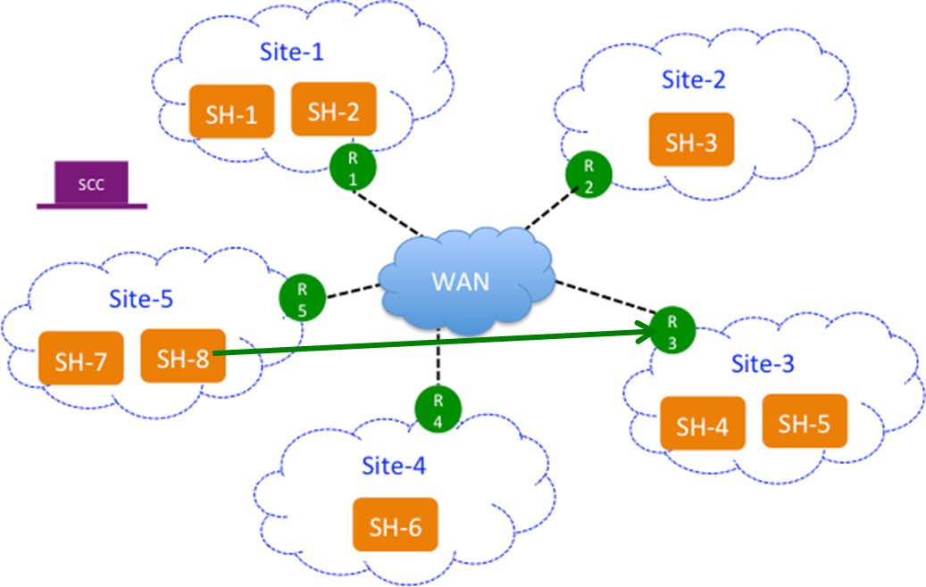
If the endpoint supports GRE encapsulation, then the probe will be successful from the other sites, otherwise the probes will fail.
If custom endpoints aren’t specified, then the SCC pushes the in-path interfaces as peers on the SteelHeads and vice a versa.
This feature is optional.
Troubleshooting
These troubleshooting tips can help you configure sites in the SCC.
Where is the Local Site field in the SCC?
The SteelHead Local Site field is replaced by the Site Name field in the SCC. The SCC field has a different name because the SCC pushes the configuration settings relative to the SteelHead receiving the push. In other words, you have specified in the SCC which SteelHead belongs to that site and you push that information to the specified SteelHead. The SteelHead Local Site field is renamed automatically.
What happened to the Default Site in the SteelHead?
The SteelHead Default Site is renamed to the site you specified as a recipient of the backhaul traffic in the SCC. In the SteelHead, the default site owns the all zero destination network (that is, 0.0.0.0), eliminating the need to configure every single Internet subnet. In the SCC, you can’t build a site and give it the 0.0.0.0 subnet because once the configuration is pushed to the SteelHead the 0.0.0.0 subnet belongs to the site that traffic is being backhauled to, which is the default site.
Why is there no peer IP address field in the SCC?
There is no field for the peer IP address to probe on the SCC because the SCC automatically fills in this value with the SteelHead in-path IP addresses. The SCC uses the SteelHead in-path IP addresses that you have associated to that site. If no SteelHead is assigned to that site, the default gateway is used. This is only relevant to path selection configurations.
What is the Internet Traffic field used for?
For path selection, the most important setting in a site is the Internet Traffic field. This field functions differently on the SteelHead. In the SCC, you specify how Internet-bound traffic is routed. You can choose Direct to Internet if you’re putting public Internet traffic directly at the site. Direct to Internet traffic sends all traffic with an unknown destination to the specified default gateway.
Your other choice is Backhaul through Site. Configure this option if you have to send your traffic back through a specific site, typically the data center. The Backhaul through Site option sends all traffic to whatever site you specify in this field and this becomes the default site on the SteelHead. On the SteelHead, the default site is automatically renamed after you push your settings, so you don’t have to configure the default site on the SteelHead. You simply specify it on the SCC.
As a best practice, always configure the data center first.
To define a site
1. Choose Manage > Topology: Sites & Networks to display the Sites & Networks page.
2. Click + Add a Site to display the pop-up window.
Defining a site
3. Complete the configuration as described in this table.
Control | Description |
Basic Information | Specify the basic information for the site: •Site Name - Specify the name of the site for example, DCEurope. Site names should reflect the location or region so that you can track issues. The site name must be unique and can’t contain special characters. Site names can contain spaces. •Site Type - Specify the site type. The basic site types are predefined: Data Center, Branch, and Headquarters. A maximum of 16 site types can be defined. •Region - Specify the region in which the site is located. Regions help in reporting and troubleshooting problems. •Description - Optionally, provide the intent of this site so that others can easily understand what this site is used for. A new site type and site region are created when the site is created. |
Contact Information | Optionally, specify the contact information for the site: •Name - Specify the name of the person responsible for the site. •Job Title - Specify the job title for the person responsible for the site. •Email - Specify the email address for the contact person for the site. •Address - Specify the address for the site. •City/Town - Specify the city or town for the site. •State/Province - Specify the state or province for the site. •Country - Specify the country the site. |
Riverbed Information | Specify the connection information for Riverbed peers for the site: •Add Appliance - Specify the hostname or serial number for the site peer. You must enter each peer separately. The peer must be registered (that is, added as an appliance) in SCC. For details about registering appliances, see “To add an appliance” on page 217. When you add a site in the SCC you don’t have to specify the IP addresses of the SteelHeads at each given site because the SCC dynamically adds them to the site configuration that it sends to the SteelHeads. |
Custom Probe | Endpoint - Path selection users can specify, on a per site basis, specific endpoints to be probed to determine path availability rather than having the SCC automatically use that site's SteelHead in-path interfaces as probe endpoints. For service sensitive path selection deployments, custom-probe endpoints can better distinguish between true path availability versus false positives or inaccurate assumptions of service availability. You use the custom probe feature to define, on a per site basis, IP addresses that must be available for a path to be considered available to use. IP addresses must be separated by a comma or semicolon. |
Network Information | Specify the subnets for the site. Separate subnets with a comma, a semicolon, or a new line. You must list all the subnets either manually or copy and paste them from a spreadsheet. |
Internet Traffic | (Use only when path selection is enabled.) Specify how Internet access is achieved at this site. •Direct to Internet - Traffic is sent based on path selection rules configured. Typically, the data center is specified as Direct to Internet because it isn’t backhauling traffic through any remote branches. •Backhaul through site - Specify the subnet to backhaul traffic through the site. All out-bound traffic is sent or relayed to the specified site, no matter what path selection rule is configured. The backhaul traffic option sends all unknown traffic to whatever site you choose in this field—this becomes the default site on the SteelHead. On the SteelHead, the default site is automatically renamed after you push your settings. You don’t need to configure the default site on the SteelHead. You simply choose it on the SCC. |
Uplinks | Click + Add New Uplink to display the controls. For detailed information, see “To define an uplink” on page 202.— or — Select a site connectivity template from the drop-down list if you have configured one. For detailed information about configuring a site connectivity template, see “To define a site connectivity template” on page 188. |
4. Click Save to save your settings.
Defining site connectivity templates
You define site connectivity templates in the Sites & Networks page.
A site connectivity template is a container for one or more uplinks that are used at different sites. We recommend you use the site connectivity template if you have the same uplinks with common uplink properties at more than one site. Common uplink properties that are independent of a site configuration are defined in a site connectivity template. The template is then applied to a site, thereby creating a copy of the uplinks of the template to the site. After the uplinks are copied to a site, you must define the site-specific configuration for the uplinks. Any changes made to the site connectivity template don’t affect the sites that have uplinks.
Site connectivity templates enable you to define the characteristics of a site once and use it for multiple sites. For example, if you add a SteelHead to the network at a new site, you can choose a site template that defines the configuration for multiple sites. The site template includes a description that explains the intent of the configuration. This description is important because if a new network administrator has to make changes to the configuration, it will be clear what type of configuration it is and how it is used.
To define a site connectivity template
1. Choose Manage > Topology: Sites & Networks to display the Sites & Networks page.
2. Under Site Connectivity Templates, click Add a Template to display the New Site dialog box and scroll down to the Add Uplinks panel.
Site connectivity template
3. Complete the configuration as described in this table.
Control | Description |
Name | Specify the name for the template. The name must be unique and can’t contain spaces or special characters. |
Add New Uplink | Click the + to expand the panel. |
Network | Select the network from the drop-down list. |
Uplink Type | Specify a name for similar functioning uplinks. On the SCC, uplink types can be used across multiple sites and path selection rules can be created using these names. The name must be unique at a site (but it can be same across different sites) so that the system can detect which path selection rule uses which uplinks. Because path selection rules are global on the SCC, you’re restricted to eight uplink types. Uplink types are the building blocks for path selection. For example, you can label uplink types as primary, secondary, and tertiary based on the path selection preference. The uplink type can be based on the type of interface or network resource, such as Verizon or global resource of uplink abstraction that’s tied to a network. On the SteelHead, this field is called the Uplink Name; on the SCC it is the Uplink Type. |
In-Path Interface | Specify the in-path interface that relays traffic from for the uplink from the drop-down list. •Is Default for inpath0_0 - Specify to make this interface the default uplink to relay traffic through the selected interface. The SCC allows you to add many uplinks tied to the same in-path interface, or virtual uplinks. The SCC doesn’t know which of these uplinks will be the default uplink. This option enables you to specify which in-path interface should be used as the default uplink •Enable GRE Tunneling - Specify for SteelHeads that are behind a firewall to provide IPv4 generic routing encapsulation (GRE) for direct uplinks used in path selection. Direct uplinks using GRE become direct tunneled uplinks. You must create direct tunneled uplinks to steer traffic over any uplink that traverses a stateful firewall between a server-side SteelHead and a client-side SteelHead. Without GRE, traffic attempting to switch midstream to an uplink that traverses a stateful firewall might be blocked. The firewall needs to track the TCP connection state and sequence numbers for security reasons. Because the firewall hasn’t logged the initial connection handshake, and has partial or no packet sequence numbers, it blocks the attempt to switch to the secondary uplink and might drop these packets. To traverse the firewall, path selection can encapsulate that traffic into a GRE tunnel. For details about firewalled path selection deployments, see the SteelHead Deployment Guide. |
Bandwidth Up | (Applicable only for QoS deployments.) Specify the bandwidth up value in kilobits per second. RiOS uses the bandwidth to precompute the end-to-end bandwidth for QoS. The SteelHead automatically sets the bandwidth for the default site to this value. The uplink rate is the bottleneck WAN bandwidth, not the interface speed out of the WAN interface into the router or switch. For example, if your SteelHead connects to a router with a 100-Mbps link, don’t specify this value—specify the actual WAN bandwidth (for example, T1 or T3). Different WAN interfaces can have different WAN bandwidths; you must enter the bandwidth link rate correctly for QoS to function properly. |
Bandwidth Down | (Applicable only for QoS deployments.) Specify the bandwidth down value in kilobits per second. RiOS uses the bandwidth to precompute the end-to-end bandwidth for QoS. The SteelHead automatically sets the bandwidth for the default site to this value. The uplink rate is the bottleneck WAN bandwidth, not the interface speed out of the WAN interface into the router or switch. For example, if your SteelHead connects to a router with a 100-Mbps link, don’t specify this value—specify the actual WAN bandwidth (for example, T1 or T3). Different WAN interfaces can have different WAN bandwidths; you must enter the bandwidth link rate correctly for QoS to function properly. |
Probe Settings | Specify the probe settings for path selection monitoring. The SCC uses ICMP pings to monitor the uplink state dynamically. If one uplink fails, traffic is redirected to the next available uplink. When the original uplink comes back up, the traffic is redirected back to it. Specify the probe settings for the uplink: •DSCP - Select the DSCP marking for the ping packet. You must select this option if the service providers are applying QoS metrics based on DSCP marking and each provider is using a different type of metric. Path selection-based DSCP marking can also be used in conjunction with PBR on an upstream router to support path selection in cases where the SteelHead is more than a single L3 hop away from the edge router. The default marking is preserve. Preserve specifies that the DSCP level or IP ToS value found on pass-through and optimized traffic is unchanged when it passes through the SteelHead. |
Probe Settings cont. | •Timeout - Specify how much time, in seconds, elapses before the system considers the uplink to be unavailable. The default value is 2 seconds. RiOS uses ICMP pings to probe the uplinks. If the probes don’t make it back within this timeout setting and the system loses the number of packets defined by the threshold value, it considers the uplink to be down and triggers an alarm. •Threshold - Specify how many time-out probes the system must receive before the uplink is considered unavailable and an alarm is triggered; the default value is 3 failed successive packets. This value also determines how many probes the system must receive to consider the uplink to be available. RiOS uses ICMP pings to monitor uplink availability. If the ping responses don’t make it back within the probe timeout and the system loses the number of packets defined by this threshold, it considers the uplink to be down and triggers an alarm. |
•Bandwidth - Specify the maximum probing bandwidth for this uplink. You can increase the efficiency of probing by limiting the number of probes that occur per second on an uplink. In the SCC when you create an uplink you can enforce a bandwidth rate limit on all probes in Probe Settings: Bandwidth field. The default bandwidth is 128 kbps. On the SteelHead, you can view your settings using the show path-selection debug uplinks CLI command. |
4. Click Save to save your settings.
Click the template name to display details about the template. Click + Add New Uplink to add additional uplinks to an existing template.
Defining site types
You define site types in the Sites & Networks page.
Site types group one or more sites based on their business organization or other functionality. Riverbed creates three basic site types for you: Data Center, Headquarters, and Branch. You can create other site types in addition to these default site types. When you create sites, you must provide the site type that the site belongs. Site types are the building blocks for QoS profiles and pushing new features in SCC 9.0 and later to SteelHeads.
You must create site and sites types before migrating or configuring QoS. When creating QoS profiles, We recommend selecting site types rather than sites to make QoS more manageable. A QoS profile is a container for QoS rules and classes that apply to a source and destination site type or site. Sites should only be selected when creating exceptions for QoS profiles containing the site types. When you push QoS profiles, only the selected site types or sites in the push are applied to the QoS profiles. For detailed information about migrating QoS policies and configuring QoS, see “Managing QoS” on page 282.
The default site types can’t be deleted or modified.
To define a site type
1. Choose Manage > Topology: Sites & Networks to display the Sites & Networks page.
2. Under Site Types, click the > to expand the page.
3. Click the + to display the New Site Type pop-up window.
Defining site types
4. Complete the configuration as described in this table.
Control | Description |
Site Type name | Specify the name for the site type. The name must be unique and can’t contain spaces or special characters. |
Description | Specify a description for the site type. This description will help you make configuration changes and to associate issues with particular sites. |
5. Click Save to save your settings.
Defining site regions
You define site regions in the Sites & Networks page.
Site regions are a group of uplinks in a particular location used for information filtering. Example site regions include North America, Europe, or Asia.
Site regions are basically a group of uplinks in a particular location. Site regions can help you configure groups of sites (that is, using site templates) and identify issues with sites.
To define a site region
1. Choose Manage > Topology: Sites & Networks to display the Sites & Networks page.
2. Under Site Regions, click the arrow to expand the page.
3. Click the + to display the New Site Region dialog box.
Defining a site region
4. Complete the configuration as described in this table.
Control | Description |
Site Region | Specify the region for the site. The name must be unique and can’t contain spaces or special characters. |
5. Click Save to save your settings.
Creating a secure transport concentrator
Secure transport concentrators are auxiliary sites which are associated with a primary site that requires secure transport. These auxiliary sites must always be linked to the primary site. The concentrators contain only appliances that will perform secure transport. The concentrators inherit most of their properties from the primary site and the properties are resolved when you perform a hybrid push from the Sites & Networks page.
Typically, the secure transport concentrator is located in a data center. In the data center, in addition to SteelHeads that perform path selection and QoS, there are devices that perform secure transport. All the networks and uplinks that go into these devices are secured. The SCC designates these devices in the site and creates an auxiliary site called a secure transport concentrator.
In the case of backhauling traffic, a branch office sends Internet-bound encrypted data to the data center that has the secure transport concentrator. At the data center, data is decrypted and path selection is performed (that is, Any - Default site - relay) rule will probed for Internet-bound traffic. Internet-bound traffic is relayed as per the rule and is sent to the Internet.
Best practices for creating a secure transport concentrator
1. Create a site for which you need secure transport, typically the data center. Define the topology for the site appropriately, that is create secure networks and uplinks. Call this SiteA.
2. Create a secure transport concentrator associated with SiteA. The SCC prompts you to add appliances and link them to the SiteA.
3. You will inherit most of the properties of SiteA (that is, the linked site). You will be prompted to import uplinks from the linked site but only for secured networks. If there are no secure networks in the associated site then the SCC issues an error.
4. The secure transport concentrator uplinks will change the gateway of the inherited uplinks. The other properties aren’t be editable.
To configure a secure transport concentrator
1. Choose Manage > Topology: Sites & Networks to display the Sites & Networks page.
2. Click + Add a Site to display the pop-up window.
4. Click Secure Transport Concentrator to expand the page.
Configuring a secure transport concentrator
5. Complete the configuration as described in this table.
Control | Description |
Secure Transport Concentrator | Specify the secure transport concentrator. Secure transport concentrators receive only the secure portion of the path selection policy. They perform dedicated encryption services for SteelHeads participating in hybrid networking. •Add Appliance - Specify the appliance from the drop-down list to be the secure transport concentrator. In the text box, specify the hostname or serial number or IP address. The concentrators contain only appliances which will perform secure transport. |
Secure Transport Concentrator Uplinks | Specify the secure transport concentrator uplinks to connect this site to securable networks. At least one uplink, which is associated with a secure and public network, is required. Click + Add New Uplink to display the controls for configuring uplinks. You can only specify the gateway IP address for this uplink. The remaining uplink attributes are inherited from the uplinks defined for the same site. |
6. Click + Add a New Uplink to expand the page.
Configuring secure transport uplinks
7. Complete the configuration as described in this table.
Control | Description |
Network | Select the network name from the drop-down list, for example, MPLS. Each uplink must have a unique interface, gateway, and probe DSCP setting. A topology doesn’t allow duplicate uplinks. |
Uplink Type | Specify a name for similar functioning uplinks. On the SCC, uplink types can be used across multiple sites and path selection rules can be created using these names. The name must be unique at a site (but it can be same across different sites) so that the system can detect which path selection rule uses which uplinks. Because path selection rules are global on the SCC, you’re restricted to eight uplink types. Uplink types are the building blocks for path selection. For example, you can label uplink types as primary, secondary, and tertiary based on the path selection preference. The uplink type can be based on the type of interface or network resource, such as Verizon or global resource of uplink abstraction that’s tied to a network. On the SteelHead, this field is called the Uplink Name; on the SCC it is the Uplink Type. |
Gateway IP | Specify the gateway IP address. |
In-Path Interface | Specify the in-path interface that relays traffic from for the uplink from the drop-down list. •Is Default for inpath0_0 - Specify to make this interface the default uplink to relay traffic through the selected interface. The SCC allows you to add many uplinks tied to the same in-path interface, or virtual uplinks. The SCC doesn’t know which of these uplinks will be the default uplink. This option enables you to specify which in-path interface should be used as the default uplink •Enable GRE Tunneling - Specify for SteelHeads that are behind a firewall to provide IPv4 generic routing encapsulation (GRE) for direct uplinks used in path selection. Direct uplinks using GRE become direct tunneled uplinks. You must create direct tunneled uplinks to steer traffic over any uplink that traverses a stateful firewall between a server-side SteelHead and a client-side SteelHead. Without GRE, traffic attempting to switch midstream to an uplink that traverses a stateful firewall might be blocked. The firewall needs to track the TCP connection state and sequence numbers for security reasons. Because the firewall hasn’t logged the initial connection handshake, and has partial or no packet sequence numbers, it blocks the attempt to switch to the secondary uplink and might drop these packets. To traverse the firewall, path selection can encapsulate that traffic into a GRE tunnel. For details about firewalled path selection deployments, see the SteelHead Deployment Guide. |
Bandwidth Up | (Applicable only for QoS deployments.) Specify the primary interface bandwidth up value in kilobits per second. RiOS uses the bandwidth to precompute the end-to-end bandwidth for QoS. The SCC automatically sets the bandwidth for the default site to this value. The uplink rate is the bottleneck WAN bandwidth, not the interface speed out of the WAN interface into the router or switch. For example, if your SteelHead connects to a router with a 100-Mbps link, don’t specify this value—specify the actual WAN bandwidth (for example, T1 or T3). Different WAN interfaces can have different WAN bandwidths; you must enter the bandwidth link rate correctly for QoS to function properly. |
Bandwidth Down | (Applicable only for QoS deployments.) Specify the primary interface bandwidth down value in kilobits per second. RiOS uses the bandwidth to precompute the end-to-end bandwidth for QoS. The SCC automatically sets the bandwidth for the default site to this value. The uplink rate is the bottleneck WAN bandwidth, not the interface speed out of the WAN interface into the router or switch. For example, if your SteelHead connects to a router with a 100-Mbps link, don’t specify this value—specify the actual WAN bandwidth (for example, T1 or T3). Different WAN interfaces can have different WAN bandwidths; you must enter the bandwidth link rate correctly for QoS to function properly. |
Probe Settings | Specify the probe settings for path selection monitoring. The SCC uses ICMP pings to monitor the uplink state dynamically. If one uplink fails, traffic is redirected to the next available uplink. When the original uplink comes back up, the traffic is redirected back to it. Specify the probe settings for the uplink: •DSCP - Select the DSCP marking for the ping packet. You must select this option if the service providers are applying QoS metrics based on DSCP marking and each provider is using a different type of metric. Path selection-based DSCP marking can also be used in conjunction with PBR on an upstream router to support path selection in cases where the SteelHead is more than a single L3 hop away from the edge router. The default marking is preserve. Preserve specifies that the DSCP level or IP ToS value found on pass-through and optimized traffic is unchanged when it passes through the SteelHead. |
Probe Settings cont. | •Timeout - Specify how much time, in seconds, elapses before the system considers the uplink to be unavailable. The default value is 2 seconds. RiOS uses ICMP pings to probe the uplinks. If the probes don’t make it back within this timeout setting and the system loses the number of packets defined by the threshold value, it considers the uplink to be down and triggers an alarm. •Threshold - Specify how many time-out probes the system must receive before the uplink is considered unavailable and an alarm is triggered; the default value is 3 failed successive packets. This value also determines how many probes the system must receive to consider the uplink to be available. RiOS uses ICMP pings to monitor uplink availability. If the ping responses don’t make it back within the probe timeout and the system loses the number of packets defined by this threshold, it considers the uplink to be down and triggers an alarm. |
•Bandwidth - Specify the maximum probing bandwidth for this uplink. You can increase the efficiency of probing by limiting the number of probes that occur per second on an uplink. The default bandwidth is 128 kbps. On the SteelHead, you can view your settings using the show path-selection debug uplinks CLI command. |
8. Click Save to save your settings.
Viewing site details
You can view site details, including the appliance, optimization savings, reachability, site type, region, path selection rules, and QoS classes in the Sites & Networks: Site Details page. You can perform these actions:
•Edit path selection rules. For details, see “Configuring path selection rules” on page 270.
•View optimization savings. For details, see “Viewing optimized throughput reports” on page 345.
•View application statistics. On the right side of the page, the throughput for the top ten applications is displayed.
•Edit QoS profiles. For details, see “Adding classes and rules to QoS profiles” on page 286.
•View sites reachability. Scroll to the bottom of the page to view site reachability.
To view site details
1. Choose Manage > Topology: Sites & Networks to display the Sites & Networks page.
2. Under Sites, scroll to the site you want to view and click View Site to display the Sites Details page.
Viewing sites details
To edit site details
1. Choose Manage > Topology: Sites & Networks to display the Sites & Networks page.
2. Under Sites, scroll to the site you want to edit and click Edit Site to display the Edit a Site Details pop-up window.
Editing a site
Defining uplinks
You define uplinks in the Sites & Networks page. Configuring a network topology requires defining uplinks.
An uplink is the last network segment connecting the local site to a network. At a high level, you can define multiple uplinks to a given network. The SteelHead monitors the state of the uplink and, based on this, selects the appropriate uplink for a packet. Selecting appropriate uplinks for packets provides more control over network link use.
Remote uplinks are also important for QoS because they define the available bandwidth for remote sites. RiOS uses the specified bandwidth to compute the end-to-end bottleneck bandwidth for QoS.
You can define an uplink based on an egress interface and, optionally, the next-hop gateway IP address. You can specify different DSCP marks per uplink for a given flow, allowing an upstream router to steer packets based on the observed marking.
The uplink probing frequency can affect the scaling and performance of hybrid networks. Leveraging the SteelHead’s traffic awareness, you can accelerate probing to sites that are seeing traffic, while backing off probing for sites that aren’t seeing traffic. Uplinks are probed at the uplink Timeout default rate of 2 seconds only if there is traffic at the site or if there is path failover, otherwise probing is backed off using the Max Backoff Interval of 1800 seconds. You configure the Max Backoff Interval when you define a network. You can change the Max Backoff Interval to whatever value are best suited for your hybrid network.
If the probe responses don’t make it back within the probe timeout period, the probe is considered lost. If the system loses the number of packets defined by the probe threshold, it considers the uplink to be down and triggers an alarm, indicating that the uplink is unavailable. If one uplink fails, the SteelHead directs traffic through another available uplink. When the original uplink comes back up, the SteelHead redirects the traffic back to it.
Path selection uses only local uplinks. You can also create site connectivity templates, which consist of a set of one or more uplinks for use with multiple sites that share the same uplink structure, such as dual uplink sites or branch sites. When the site connectivity template is applied to a site, the uplinks defined in the template uplinks are cloned. For details about site templates, see
“Defining site connectivity templates” on page 187.For detailed information about defining tunneled uplinks, see the SteelHead User Guide for SteelHead CX.
To define an uplink
1. Choose Manage > Topology: Sites & Networks to display the Sites & Networks page.
2. Click + Add a Site and scroll down to the Add Uplinks.
3. Click + Add a New Uplink to expand the page.
Defining an uplink
4. Complete the configuration as described in this table.
Control | Description |
Network | Select the network name from the drop-down list, for example, MPLS. |
Uplink Type | Specify a name for similar functioning uplinks. On the SCC, uplink types can be used across multiple sites and path selection rules can be created using these names. The name must be unique at a site (but it can be same across different sites) so that the system can detect which path selection rule uses which uplinks. Because path selection rules are global on the SCC, you’re restricted to eight uplink types. Uplink types are the building blocks for path selection. For example, you can label uplink types as primary, secondary, and tertiary based on the path selection preference. The uplink type can be based on the type of interface or network resource, such as Verizon or global resource of uplink abstraction that’s tied to a network. On the SteelHead, this field is called the Uplink Name; on the SCC it is the Uplink Type. |
Gateway IP | Specify the gateway IP address. |
In-Path Interface | Specify the in-path interface that relays traffic from for the uplink from the drop-down list. •Is Default for inpath0_0 - Specify to make this interface the default uplink to relay traffic through the selected interface. The SCC allows you to add many uplinks tied to the same in-path interface, or virtual uplinks. The SCC doesn’t know which of these uplinks will be the default uplink. This option enables you to specify which in-path interface should be used as the default uplink •Enable GRE Tunneling - Specify for SteelHeads that are behind a firewall to provide IPv4 generic routing encapsulation (GRE) for direct uplinks used in path selection. Direct uplinks using GRE become direct tunneled uplinks. You must create direct tunneled uplinks to steer traffic over any uplink that traverses a stateful firewall between a server-side SteelHead and a client-side SteelHead. Without GRE, traffic attempting to switch midstream to an uplink that traverses a stateful firewall might be blocked. The firewall needs to track the TCP connection state and sequence numbers for security reasons. Because the firewall hasn’t logged the initial connection handshake, and has partial or no packet sequence numbers, it blocks the attempt to switch to the secondary uplink and might drop these packets. To traverse the firewall, path selection can encapsulate that traffic into a GRE tunnel. For details about firewalled path selection deployments, see the SteelHead Deployment Guide. |
Bandwidth Up | (Applicable only for QoS deployments.) Specify the primary interface bandwidth up value. RiOS uses the bandwidth to precompute the end-to-end bandwidth for QoS. The SCC automatically sets the bandwidth for the default site to this value. The uplink rate is the bottleneck WAN bandwidth, not the interface speed out of the WAN interface into the router or switch. For example, if your SteelHead connects to a router with a 100-Mbps link, don’t specify this value—specify the actual WAN bandwidth (for example, T1 or T3). Different WAN interfaces can have different WAN bandwidths; you must enter the bandwidth link rate correctly for QoS to function properly. |
Bandwidth Down | (Applicable only for QoS deployments.) Specify the primary interface bandwidth down value. RiOS uses the bandwidth to precompute the end-to-end bandwidth for QoS. The SCC automatically sets the bandwidth for the default site to this value. The uplink rate is the bottleneck WAN bandwidth, not the interface speed out of the WAN interface into the router or switch. For example, if your SteelHead connects to a router with a 100-Mbps link, don’t specify this value—specify the actual WAN bandwidth (for example, T1 or T3). Different WAN interfaces can have different WAN bandwidths; you must enter the bandwidth link rate correctly for QoS to function properly. |
Probe Settings | Specify the probe settings for path selection monitoring. The SCC uses ICMP pings to monitor the uplink state dynamically. If one uplink fails, traffic is redirected to the next available uplink. When the original uplink comes back up, the traffic is redirected back to it. Specify the probe settings for the uplink: •DSCP - Select the DSCP marking for the ping packet. You must select this option if the service providers are applying QoS metrics based on DSCP marking and each provider is using a different type of metric. Path selection-based DSCP marking can also be used in conjunction with PBR on an upstream router to support path selection in cases where the SteelHead is more than a single L3 hop away from the edge router. The default marking is preserve. Preserve specifies that the DSCP level or IP ToS value found on pass-through and optimized traffic is unchanged when it passes through the SteelHead. |
Probe Settings cont. | •Timeout - Specify how much time, in seconds, elapses before the system considers the uplink to be unavailable. The default value is 2 seconds. RiOS uses ICMP pings to probe the uplinks. If the ping responses don’t make it back within this timeout setting and the system loses the number of packets defined by the threshold value, it considers the uplink to be down and triggers an alarm. •Threshold - Specify how many time-out probes the system must receive before the uplink is considered unavailable and an alarm is triggered; the default value is 3 failed successive packets. This value also determines how many probes the system must receive to consider the uplink to be available. RiOS uses ICMP pings to monitor uplink availability. If the ping responses don’t make it back within the probe timeout and the system loses the number of packets defined by this threshold, it considers the uplink to be down and triggers an alarm. |
•Bandwidth - Specify the maximum probing bandwidth for this uplink. You can increase the efficiency of probing by limiting the number of probes that occur per second on an uplink. The default bandwidth is 128 kbps. On the SteelHead, you can view your settings using the show path-selection debug uplinks CLI command. |
5. Click Save to save your settings.
Defining uplink types
You define uplink types in the Sites & Networks page.
An uplink type is a name for similar functioning uplinks. On the SCC, uplink types can be used across multiple sites and path selection rules can be created using these names. The name must be unique at a site (but it can be same across different sites) so that the system can detect which path selection rule uses which uplinks. Because path selection rules are global on the SCC, you’re restricted to eight uplink types.
Uplink types are the building blocks for path selection. You select the path preference order using the uplink types created, and it is used in various sites. We recommend that you reuse the same uplink types at different sites in order to label uplinks based on the preference for path selection. For example, you can label uplink types as primary, secondary, and tertiary based on the path selection preference. The uplink type can be based on the type of interface or network resource, such as Verizon or global resource of uplink abstraction that’s tied to a network.
On the SteelHead, this field is called the Uplink Name, on the SCC it is the Uplink Type. We recommend using the same name for an uplink in all sites connecting to the same network.
To define an uplink type
1. Choose Manage > Topology: Sites & Networks to display the Sites & Networks page.
2. Under Uplink Types, click the > to expand the page.
3. Click the + to display the New Uplink Type dialog box.
New uplink types
4. Complete the configuration as described in this table.
Control | Description |
Network | Specify the network for the uplink type from the drop-down list. |
Uplink Type | Specify a name for similar functioning uplinks. On the SCC, uplink types can be used across multiple sites and path selection rules can be created using these names. The name must be unique at a site (but it can be same across different sites) so that the system can detect which path selection rule uses which uplinks. Because path selection rules are global on the SCC, you’re restricted to eight uplink types. Uplink types are the building blocks for path selection. For example, you can label uplink types as primary, secondary, and tertiary based on the path selection preference. The uplink type can be based on the type of interface or network resource, such as Verizon or global resource of uplink abstraction that’s tied to a network. On the SteelHead, this field is called the Uplink Name; on the SCC it is the Uplink Type. |
5. Click Save to save your settings.
Managing appliances
You manage Riverbed appliances in the Appliances page. The SCC uses appliance groups and appliance policies to facilitate centralized configuration, management, and reporting of remote Riverbed appliances. This section includes these topics:
SCC 9.0 introduced the concept of sites, networks, and uplinks to create a topology for deployments of Riverbed appliances. Sites, networks, and uplinks are required in 9.0 or later for path selection, simplified QoS, and the secure transport features. For detailed information about configuring sites, networks, and uplinks, see
“Managing Interceptor clusters” on page 298. For detailed information about migrating appliances to sites and networks, see
“Migrating appliances to sites” on page 209.Organizing remote appliances into appliance groups enables you to more effectively manage, monitor, and configure Riverbed appliances. For example, at the group level you can apply policies, push configurations, set passwords, and so forth. Appliance groups can be based on location, similarity of features, or whatever criteria you choose. All groups and appliances are contained in the root default Global group. The SCC supports up to 1500 appliance groups.
If you have a deployment of 1500 or more appliances, you might experience delays in legacy and hybrid networking pushes and during the initial upgrade of the software.
Appliance policies are a set of configuration settings for an appliance or an appliance group. All policy configurations from the Global group are inherited by all child groups and individual appliances. You can apply a policy to an appliance group and push configuration changes to members of a group with a single action. To modify configurations, you can apply different policies at the group or appliance level. For greater flexibility, you can configure policies to inherit some feature-set values from the parent group but override others. For detailed information about adding and configuring policies, see
“Managing path selection” on page 268.The Appliances page contains an Appliance/Group table that displays all appliances and appliance groups managed by the SCC. The data from managed appliances is cached by the SCC every five minutes. Alarms poll the cached data every five minutes, therefore, the data can lag up to ten minutes between the event happening on the managed appliance and the SCC triggering an alarm. The Appliance/Group table varies according to the operation you have chosen to perform.
Control | Description |
Groups and Managed Appliances | Lists individual appliances or by appliance group membership. •Click the + next to the appliance group name to expand or collapse the child groups or appliances. •Click the > next to the appliance group name to expand or collapse the page to assign policies or edit group properties. •Click the > next to the appliance name to expand or collapse the page to add or remove policies, configure appliance policies, edit appliance settings, run appliance utilities (that is, reconnect and change the serial number), and view inherited policies. |
Product/Model | Displays the appliance type (for example, SteelHead, SteelHead EX, Interceptor, or SteelFusion) and the model number. |
Connection | Specifies the current connection status for the SCC and the appliance and displays the alarm status for the appliance. The status represents the most severely triggered alarm. If two equally severe alarms have been triggered, the status representing the newer alarm is displayed. •Under Connection, click the error message to go to the Appliance Details page where the appliance alarms and their status are listed. |
 Cluster | Specifies the appliance is part of a cluster.
|
 Branch Managed | Specifies the appliance is managed individually at the branch office. You can’t manage this SteelHead from the SCC. |
 Auto-Configure | Specifies that a policy push will occur automatically the next time the appliance connects.
|
 Push Recommended | Specifies that the configuration shared by this appliance and the SCC has changed and a push is required to synchronize the appliance. |
Policies | Displays the policies assigned to the group. |
Site | Displays the site that this appliance belongs to. |
Time Zone | Displays the time zone for the appliance: for example US/Pacific. |
The Interceptor and the SteelHead Mobile have limited functionality in the Appliance/Group table.
Migrating appliances to sites
If you’re planning on configuring the hybrid networking features: path selection, simplified QoS, or secure transport you must migrate your appliances to sites, networks, and uplinks. For detailed information about sites, networks, and uplinks, see
“Managing Interceptor clusters” on page 298. Prior to 9.0 the management paradigm for the SCC was appliances and appliance groups. The SCC includes a migration wizard with CSV import and export so that you can easily migrate appliances to sites.
With defined sites, you can easily track user issues based on the location of the appliance and troubleshoot problems. Sites are required for path selection, QoS, and secure transport. For detailed information about sites, see
“Defining sites” on page 182.The SCC provides these migration tools:
•Bulk migration using a CSV template - Bulk migration allows you to migrate groups of appliances to more than one site in a single operation. The bulk migration wizard provides a custom CSV template. The SCC automatically populates the template with the appliances, group names, serial numbers, hostnames, and IP addresses currently managed by the SCC. For details, see
“To bulk migrate appliances to sites using the CSV template” on page 210. •Create a new site from selected appliances - Alternatively you can create individual sites manually using the Create a New Site form in the Appliances page or the detailed New Sites form (for features such as secure transport) on the Sites & Networks page. Creating sites allows the user to map their unassigned appliances to sites. For details, see
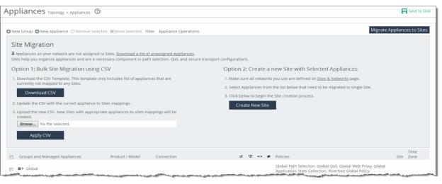
“To create a new site from selected appliances” on page 211. To bulk migrate appliances to sites using the CSV template
1. Choose Manage > Topology: Appliances to display the Appliances page.
2. Click Migrate Appliances to Sites to display the Site Migration page.
Migrating appliances to sites
3. Click Download CSV to download the CSV template and open it in Excel.
4. Define the sites. The Site Name, Site Type, Site Region, Subnets, and Peers (if custom endpoints configured) are required. The Site Name column doesn’t accept commas. We recommend creating the region and type before you populate this CSV template.
Object type
(i.e., site; required) | Site name (required) Don’t use commas. | Site type (required) | Site region (required) | Subnets (comma-separated list) | Connectivity template | Uplink1 gateway |
Site | Sacramento CA | Branch | USA | 10.0.1.0/24, 10.0.2.0/24 | Optional | Optional |
Site | San Francisco CA | Branch | USA | 10.0.3.0/24, 10.0.4.0/24 | Optional | Optional |
Uplink Gateway fields are ignored unless a connectivity template is specified. If one is specified, then Uplink Gateway is required. Internet Traffic can be either Direct-to-Net or backhauled through a site. Specify a site to backhaul through or leave blank for Direct-to-Net.
5. Associate appliances to sites. The Object Type, Serial Number, and Site Name are required. The Site Name doesn’t accept commas. You can also assign the appliance to an already existing site: for example, existing sites.
Object type
(i.e., appliance; required) | Serial number (required) | Hostname | IP address | Site name
(required) Don’t use commas. |
SteelHead | C48YG0000490F | Pacific | 10.0.1.0/24 | Sacramento CA |
SteelHead EX | C48WN000099B | Atlantic | 10.0.1.2/24 | New York New York |
6. Close and save the CSV file.
7. On the Appliances page under Option 1, click Browse to navigate to the CSV template.
8. Click Apply CSV to upload the new CSV template to the SCC. New sites with appropriate appliances to sites mappings are created and displayed in the Appliance/Group table.
To create a new site from selected appliances
1. Choose Manage > Topology: Appliances to display the Appliances page.
2. Select the appliances you want to migrate.
3. Click Migrate Appliances to Sites to display the Site Migration panel.
Migrating appliances to sites
4. Select the appliances in the Appliance/Group table to be migrated to single site.
Selecting appliances to migrate in appliance/group table
5. Under Option 2, click Create New Site to expand the page and display the controls to create a site. Under Riverbed Appliances, the selected appliances automatically appear.
Selected appliances displayed in the create a new site panel
Managing appliance groups
All groups are based on a nested hierarchy. Appliance groups allow you to assign policies to appliances in that group. Global group policies can be overridden by policies lower in the hierarchy. The hierarchical management of devices allows access to all of the Riverbed appliances and in a global infrastructure.
You should carefully design your network hierarchy so that you can identify what policies are needed on the appliances in each group. Carefully designing the group hierarchy will ensure that you implement the best solution for your network.
You can perform these actions on appliance groups in the Appliances page:
All groups are based on a nested hierarchy. Appliance groups allow you to assign policies to appliances in that group. Global group policies can be overridden by policies lower in the hierarchy. The hierarchical management of devices allows access to all of the Riverbed appliances in a global infrastructure.
To add a group
1. Choose Manage > Topology: Appliances to display the Appliances page.
2. Click New Group to expand the page.
Adding a group
3. Complete the configuration as described in this table.
Control | Description |
Name | Specify the name for the group. |
Parent Group | Select the parent group from the drop-down list. The default value is Global. |
Comment | Specify a description to help you identify the group. |
Add | Adds the group to the Appliance/Group table. The SCC redisplays the table and applies your changes to the running configuration, that’s stored in memory. |
4. Click Save to Disk to save the settings permanently.
To edit an appliance group
1. Choose Manage > Topology: Appliances to display the Appliances page.
2. In the Appliances table, click the group name to expand the page.
3. Click Edit Group to modify the parent group and comments.
Editing a group
4. Select the parent group from the drop-down list.
5. Type a comment to help you identify the group in the Comment text box.
6. Click Apply to apply your settings to the running configuration.
To add a policy to an appliance group
1. Choose Manage > Topology: Appliances to display the Appliances page.
2. Click the group name to expand the page.
3. Click Policies to expand the page.
Adding or removing policies
4. Click Add/Remove Policies to display the pop-up window.
Adding and removing policies
5. Select the policy you want to add. A message is displayed stating the policy has been added. To remove the policy, click Revert.
The policy is displayed in the Policy Pages table. The SCC redisplays the table and applies your changes to the running configuration, that’s stored in memory.
6. Click Done to return to the Appliance/Group table.
Adding appliances
You can manage remote appliances in the Appliances page. SteelHeads must be registered with the SCC so that you can monitor and manage them with the SCC. SteelHeads are designed to send a registration request periodically to the SCC so that they’re automatically registered. If can take up to an hour for all registered SteelHeads to appear in the Appliances page. An unregistered SteelHead appears on the Appliances page with the error “NO ADDRESS SPECIFIED.” You can manually add the SteelHead in the Appliances page.
Adding a Riverbed appliance creates a connection between the SCC and the appliance. After you have registered an appliance, you can configure features and push configurations to remote appliances by group or for individual appliances using the SCC. The SCC collects statistics, health, and connection history information from registered appliances.
If you have SteelHeads that are behind a firewall you can run a CLI command that creates an SSL authorized port. For detailed information about adding an authorized port using the CLI, see “Connecting SteelHeads when the SCC is behind a firewall” on page 26.
To view how many SteelHeads an SCC can manage, go to Knowledge Base article
S14106.
You can perform these actions on remote appliances:
If you’re planning to configure path selection, QoS, or secure transport in SCC 9.0 or later you must migrate your existing appliances to sites and networks. For detailed information about migrating to sites, networks, and uplinks, see “Migrating appliances to sites” on page 57.
To add an appliance
1. Choose Manage > Topology: Appliances to display the Appliances page.
2. Click + New Appliance to expand the page.
Adding an appliance
3. Complete the configuration as described in this table.
Control | Description |
Appliance Type | Identify the appliance type. The options are: •SteelHead •SteelHead EX •SteelCentral Controller for SteelHead Mobile •SteelHead Interceptor •SteelFusion Core |
Serial Number | Specify the serial number for the appliance. The serial number is required to register an appliance. |
Hostname or IP Address | Optionally, specify the IP address or hostname for the remote appliance. |
Comment | Optionally, specify a description to help you identify the appliance or appliance group. |
Group | Select the group from the drop-down list. The default value is Global. |
Branch Managed | Select to prevent any remote action from being performed on the specified appliance. For example, you wouldn’t be able to push configurations to this appliance from the SCC. |
Auto Configure | (Use only when policies have been configured.) Select to automatically push the current configuration (as defined by the policies for the appliance or appliance group) to the current SteelHead the next time it connects to the SCC. This feature is available only when the SteelHead is disconnected. This setting is automatically disabled after a policy push. |
User Name | Specify the administrator username for the remote appliances. |
Password | Specify the corresponding password. |
Confirm Password | Confirm the corresponding password. |
Add | Adds the appliance to the Appliance/Group table. The SCC redisplays the table and applies your changes to the running configuration, that’s stored in memory. |
4. Click Save to Disk to save the settings permanently.
To remove an appliance
1. Choose Manage > Topology: Appliances to display the Appliances page.
2. Select the check box next to the appliance name that you want to remove and click Remove Selected. The SCC redisplays the table and applies your changes to the running configuration, that’s stored in memory.
To move an appliance or a group
1. Choose Manage > Topology: Appliances to display the Appliances page.
2. Select the check box next to the appliance name or group name that you want to move.
3. Click Move Selected and move the appliance or group up or down. Click Cancel Move to return the appliance to the original position in the list.
When you move a group, all appliances and subgroups within that group move.
4. Click Save to save the settings permanently.
Filtering the display of appliances
You can define filters to display only those appliances that need to be managed in the Appliances page.
To filter the display of managed appliances
1. Choose Manage > Topology: Appliances to display the Appliances page.
2. In the menu bar at the top of the page, click Filter to expand the page.
Filtering an appliance
3. Select the appliances that match the specified filter criteria.
4. Type an expression into the fields to filter the display of appliances. The filter applies only to appliances, not groups.
5. Click Apply Filter to select the appliances that match the criteria specified.
Managing appliance settings
You can manage these appliance-specific settings in the Appliances page: Appliances tabs.
•Configure Appliance Pages - You can configure or modify appliance feature settings, such as host settings, SSL settings, base interfaces, and so on. For details, see
“Managing appliance pages” on page 239. To display appliance tabs
1. Choose Manage > Topology: Appliances to display the Appliances page.
2. Select the name of the appliance you want to edit to expand the page and display the Appliance tabs.
Displaying appliance tabs

3. You can perform operations on policies, configuration settings, appliance properties, appliance utilities (that is, reconnect and serial number), and inherited policies.
To add a policy to an appliance
1. Choose Manage > Topology: Appliances to display the Appliances page.
2. Select the appliance name to expand the page and display the Appliance tabs.
Adding a policy to an appliance
3. Click the + Add/Remove Policies to display the pop-up window.
Displaying the add/remove policy
4. Select the policy you want to add. A message is displayed stating the policy has been added. To remove the policy, click Revert.
5. Click Done to return to the appliances and group table.
To edit appliance properties
1. Choose Manage > Topology: Appliances to display the Appliances page.
2. Select the appliance name to expand the page and display the Appliance tabs.
3. Select the Edit Appliance tab to display the appliance properties.
4. Complete the configuration as described in this table.
Control | Description |
Serial Number | Displays the serial number for the appliance. |
Hostname or IP Address | Specify the hostname or IP address for the appliance. |
Comment | Specify a comment to help you identify the appliance. |
Group | Select a group from the drop-down list. The default group is Global. |
Branch Managed | Select to prevent any remote action from being performed on the specified appliance. For example, you wouldn’t be able to push configurations to this appliance from the SCC. |
Trusted | Select to untrust an appliance. Only applicable to manually trusted appliances. |
Auto Configure | (Use only when the policies have been configured.) Select to automatically push the current configuration (as defined by the policies for the appliance or appliance group) to the current remote appliance the next time it connects to the SCC. This feature is available only when the remote appliance is disconnected. This setting is automatically disabled after the push. |
User Name | Specify the username for the appliance. |
Password/Confirm Password | Specify and confirm the password for the appliance. |
Apply | Applies your settings to the running configuration. |
5. Click Save to Disk to save your settings permanently.
To run appliance utilities
1. Choose Manage > Topology: Appliances to display the Appliances page.
2. Select the name of the appliance you want to edit to display the Edit Appliance tab.
3. Click Appliance Utilities to display the Editing Appliance Configuration <appliance>, Utilities panel.
Running appliances utilities
4. Complete the configuration as described in this table.
Control | Description |
Update | Click Update to update the current appliance serial number. Sets the serial number for the appliance to the actual value stored on the appliance itself. The value is changed system-wide; the appliance remains accessible. The appliance must be connected to update the serial number. |
Reconnect | Click Reconnect to reconnect the SCC to the current appliance. You can establish a new connection to an appliance in about 30 seconds. Reconnecting doesn’t affect policy configurations. |
To view policies inherited by an appliance
1. Choose Manage > Topology: Appliances to display the Appliances page.
2. Select the name of the appliance you want to view to display the Edit Appliance tab.
3. Select the Inherited Policies tab to display the policies for the appliance.
Displaying inherited policies
4. Select the page to display the inherited policies.
Managing appliance operations
You can perform these appliance operations for specified appliances or appliance groups in the Appliances page: Appliance Operations.
Appliance operation | Task |
Push Polices | |
Replace (Generate) Peering Certificates | |
License Update | |
Start/Stop Services | |
Shutdown | |
Set Password | |
Unlock the Secure Vault | |
Change Secure Vault Password | |
Send CLI Commands | |
SteelCentral NetShark | |
Disable the SSL Server Certificate Export | |
Remove SteelFusion Configuration | |
Join/Leave Windows Domain | |
Pushing policies to selected appliances or appliance groups
You can push SCC configurations (in the form of policies) to selected appliances or appliance groups.
Any changes made to policies on the SCC don’t take effect on remote appliances until the new configurations are pushed to the appliances.
When you push SCC configurations (in the form of policies) to selected appliances or appliance groups, appliance page configurations are also pushed.
For details about appliance page configurations, see
“Managing appliance pages” on page 239. Any scheduled operations on appliance groups execute according to the time on the SCC, not the time on the remote appliance. For example, if the SCC clock is set to Pacific Daylight Time (PDT) but the remote appliance clock is set to Central European Summer Time (CEST), then an operation scheduled for midnight on the SCC (PDT) is executed at 9:00 AM on the remote appliance (CEST). This operation applies only to SteelHeads and Interceptors.
For detailed information about pushing global policies, see
“Performing global policy pushes” on page 235.You can abort a pending policy push using the SCC CLI command cmc policy abort job <job-id>.
To push a configuration to an appliance or an appliance group
1. Choose Manage > Topology: Appliances to display the Appliances page.
2. Click Appliance Operations to display the Appliance Operations page.
3. Select the appliances or appliance groups to which you want to push settings in the appliances table.
4. Select Push Policies from the operation drop-down list.
5. Complete the configuration as described in this table.
Control | Description |
Include Path Selection, QoS, and Applications (RiOS 9.0 and later); Web Proxy and Application Stats Collection (RiOS 9.1 and later) | Specify to include path selection rules, QoS profiles, applications, web proxy settings, and application statistics in the policy push. Applicable to RiOS 9.0.x or later. |
Restart Optimization Service If Required | Specify to automatically restart the RiOS service on the appliances after the push. |
Restart QoS Service If Required | Specify to automatically restart the QoS service, if required. •For legacy outbound QoS (Advanced) policy changes: The QoS service must first be disabled if the policy push changes queue type of an existing QoS class. If the QoS service isn’t disabled the policy push fails. •For legacy outbound QoS (Basic) and outbound QoS (Advanced): Disables the QoS service on all appliances that you push to. This option temporarily disrupts QoS enforcement. |
Schedule Deferred Push | Specify to schedule the action for a later time and date. If this option isn’t selected, the action occurs the next time the appliance connects. •Date and Time - Specify the date and time in this format: yyyy/mm/dd hh:mm:ss This operation applies only to SteelHeads and Interceptors. |
Push | Pushes your configuration changes to the selected appliances and groups. Note: You can abort a pending policy push using the SCC CLI command:
cmc policy abort job <job-id> |
Replacing (generating) peering certificates
You can replace the peering certificates used to secure the inner channel between the SteelHeads by generating new private keys and self-signed public certificates.
If possible, the certificates are signed by the certificate authority, otherwise they’re self-signed.
A policy push must be initiated to all SteelHeads for the new certificates to be used in peering. If the policy push excludes any affected SteelHeads, SSL optimization to the SteelHeads doesn’t work properly.
If CA is enabled, all newly generated certificates are automatically be signed. The existing certificates must be replaced to be signed.
To replace (generate) peering certificates
1. Choose Manage > Topology: Appliances to display the Appliances page.
2. Click Appliance Operations to display the Appliance Operations page.
3. Select Replace (Generate) Peering Certificates from the operation drop-down list.
4. Under Self-Signed Certificate, complete the configuration as described in this table.
Control | Description |
Common Name | Specify the common name of a certificate. •Appliance Hostname - Select if the common name is the hostname or IP address. •Custom Name - Select to specify a common name other than the hostname or IP address. To facilitate configuration, you can use wildcards in the name: for example, *.example.com. If you have three origin servers using different certificates, such as webmail.example.com, internal.example.com, and marketingweb.example.com, on the server-side SteelHeads, all three server configurations can use the same certificate name *.example.com. |
Organization Name | Specify the organization name (for example, the company). |
Organization Unit Name | Specify the organization unit name (for example, the section or department). |
Locality | Specify the city. |
State | Specify the state. |
Country | Specify the country (2-letter code only). |
Email Address | Specify the email address of the contact person. |
Validity Period | Specify how many days the certificate is valid. |
5. Click Replace to replace the peering certificates.
Enabling and disabling image signature verification
Perform this task to enable or disable image signature verification on a group of managed appliances. For more information about image signature verification, see “Image signature verification” on page 22.
This feature is enabled by default. We strongly recommend that it remain enabled at all times. Disable this feature only when absolutely necessary.
To enable image signature verification on a group of managed appliances
1. Choose Manage > Topology: Appliances.
2. Click Appliance Operations to expand the page.
3. Select the appliances or groups of appliances that you want to enable with this feature.
4. Select Image Signature Verification from the operation drop-down list.
5. Check the Image Signature Verification check box.
6. Click Apply.
Updating licenses
The SCC fetches and pushes licenses to selected appliances or groups. You can also fetch a license from the Riverbed License portal and store it locally. This option ignores the selected appliances and applies the license to all appliances specified in the license file.
To update a license
1. Choose Manage > Topology: Appliances to display the Appliances page.
2. Click Appliance Operations to expand the page.
3. Select License Update from the operation drop-down list.
4. Under License Update Method, complete the configuration as described in this table.
Control | Description |
Update License using Riverbed Licensing Portal | Select the option to update the license using the Riverbed Licensing Portal. |
From Local File | Click this option and specify the path, or click Browse to navigate to the local file directory. |
Update | Updates the current license. |
Starting and stopping appliances
You can start and stop the system service on selected appliances and appliance groups.
For detailed information about user permissions, see “User permissions” on page 620.
To start or stop an appliance or an appliance group
1. Choose Manage > Topology: Appliances to display the Appliances page.
2. Click Appliance Operations to expand the page.
3. Select Start/Stop Services from the operation drop-down list.
4. Complete the configuration as described in this table.
Control | Description |
Service Action | Select Start, Stop, or Restart from the drop-down list. |
Clean Data Store | Specify this option to clear the RiOS data store. This option only applies to SteelHeads. |
Schedule Deferred Service Action | Specify to schedule the action for a later time and date. If this option isn’t selected, the action occurs the next time the appliance connects. •Date and Time - Specify the date and time in this format: yyyy/mm/dd hh:mm:ss This option only applies to SteelHeads and Interceptors. |
Apply | Click Apply to apply your changes to the selected appliances or appliance groups. |
The results of this operation can be viewed in the Operation History page. For detailed information about operation history, see “Managing appliance operation history” on page 313.
Shutting down appliances
Shut down the system on selected appliances and appliance groups. You can also clean the data store and schedule a shutdown.
To shut down an appliance or an appliance group
1. Choose Manage > Topology: Appliances to display the Appliances page.
2. Click Appliance Operations to expand the page.
3. Select Shutdown from the operation drop-down list.
4. Complete the configuration as described in this table.
Control | Description |
Clean Data Store | Specify to clean the RiOS data store. |
Schedule Deferred Shutdown | Specify to schedule the action for a later time and date. If this option isn’t selected, the action occurs the next time the appliance connects. •Date and Time - Specify the date and time in this format: yyyy/mm/dd hh:mm:ss |
Shutdown | Select the check box next to the name of the appliance and appliance groups you want to shut down and click Shutdown. |
The results of this operation can be viewed in the Operation History page. For detailed information about operation history, see “Managing appliance operation history” on page 313.
Setting the password for appliances
You can set the password for administrator and monitor users on selected appliances and groups.
The SCC sets the password used to connect with the remote appliance. The SCC automatically updates the password that’s used by the SCC to connect with the remote appliance.
To set the password for an appliance or an appliance group
1. Choose Manage > Topology: Appliances to display the Appliances page.
2. Click the Appliance Operations tab to expand the page.
3. Select Set Password from the operation drop-down list.
4. Complete the configuration as described in this table.
Control | Description |
User | Type admin or monitor in the text box. |
Password | Specify the password. |
Confirm Password | Confirm the password. |
Set Password | Sets the specified password. |
The results of this operation can be viewed in the Operation History page. For detailed information about operation history, see “Managing appliance operation history” on page 313.
Unlocking the secure vault
You can unlock the Secure Vault on selected appliances and appliance groups.
The SCC unlocks the secure vault on the selected appliances or groups if the correct password has been specified. If successful, this operation also automatically updates the stored copy of the secure vault password for each selected appliance.
When the secure vault on an appliance or an appliance group is locked, you can’t push some configuration settings.
This operation applies only to SteelHeads.
To unlock the secure vault on an appliance or an appliance group
1. Choose Manage > Topology: Appliances to display the Appliances page.
2. Click Appliance Operations to display the Appliance Operations page.
3. Select Unlock Secure Vault from the operation drop-down list.
4. Specify the password and click Unlock Vault to unlock the secure vault on the selected appliances or appliance groups.
The results of this operation can be viewed in the Operation History page. For detailed information about operation history, see “Managing appliance operation history” on page 313.
Changing the secure vault password
You can change the password for the Secure Vault on selected appliances and appliance groups.
The SCC must know the current secure vault password, that’s set on the SSL configuration page of each appliance. This operation automatically updates the stored copy of each password on the selected appliance.
This operation applies only to SteelHeads, SteelHead EXs, and Mobile Controllers.
To change the secure vault password on an appliance or an appliance group
1. Choose Manage > Topology: Appliances to display the Appliances page.
2. Click Appliance Operations to display the Appliance Operations page.
3. Select Change Secure Vault Password from the operation drop-down list.
4. Specify the current password, or leave the text box blank if the factory default password is.
5. Specify the new vault password, or leave the text box blank to reset to the factory default password.
6. Confirm the new secure vault password.
7. Click Change Password to change the secure vault password.
The results of this operation can be viewed in the Operation History page. For detailed information about operation history, see “Managing appliance operation history” on page 313.
Sending CLI commands
You can send a set of CLI commands to the selected appliances and groups.
To send CLI commands to an appliance or an appliance group
1. Choose Manage > Topology: Appliances to display the Appliances page.
2. Click Appliance Operations to display the Appliance Operations page.
3. Select Send CLI Commands from the operation drop-down list.
4. Complete the configuration as described in this table.
Control | Description |
Text field | Paste or type the set of CLI commands in the provided text field. Each command must be on a separate line. This feature provides the flexibility to configure your appliances using CLI commands. For example, using the CLI commands in policies: •enables you to configure new appliance features. •enables you to override specific configuration items at a subpage granularity without maintaining multiple copies of otherwise identical policies. Sending CLI commands has these restrictions: •The SCC can’t parse the CLI commands itself and perform a check to verify if they’re compatible with the rest of the configuration, therefore, a failure is harder to diagnose. •The CLI commands from all assigned policies are sent with every push. Given this, you must check each policy that’s assigned to each parent group and individually check its details to review exactly what was pushed. |
Schedule Deferred Command Execution | Specify to schedule the action for a later time and date. If this option isn’t selected, the action occurs the next time the appliance connects. •Date and Time - Specify the date and time in this format: yyyy/mm/dd hh:mm:ss |
Send | Executes the commands on the appliance. |
Starting or stopping SteelCentral NetShark service
You can start or stop the SteelCentral NetShark service; it can take up to five minutes to take effect.
This operation applies only to SteelHeads and can take up to five minutes to take effect.
To start or stop the SteelCentral Shark service
1. Choose Manage > Topology: Appliances to display the Appliances page.
2. Click Appliance Operations to display the Appliance Operations page.
3. Select SteelCentral NetShark from the operation drop-down list.
4. Complete the configuration as described in this table.
Control | Description |
Service Action | Select Start or Stop from the drop-down list. |
Apply | Applies your settings to the running configuration. |
Disabling SSL server certificate export
You can disable the SSL server certificate export feature. For security reasons, once a certificate export has been disabled, it can’t be reenabled.
This operation applies only to SteelHeads.
Consider making SSL server certificates and private keys nonexportable with your particular security goals in mind. Before doing so, you must have a thorough understanding of its impact. Use caution and consider these best practices before making SSL configurations nonexportable:
•After disabling export on a new SteelHead running 7.0.1, you can’t reenable it unless you clear the secure vault and perform a factory reset on the SteelHead. (Performing a factory reset results in losing your configuration settings.)
•After upgrading a SteelHead to 7.0.1 and disabling export, you can’t export any preexisting or newly added server certificates and private keys to another SteelHead.
•After disabling export, any newly added server certificates and keys are marked as nonexportable.
•After disabling export and then downgrading a SteelHead to a previous RiOS version, you can’t export any of the existing server certificates and private keys. You can export any newly added server certificates and private keys.
•Disabling export prevents you from copying the secure vault content.
To disable SSL server certificate export
1. Choose Manage > Topology: Appliances to display the Appliances page.
2. Click Appliance Operations to display the Appliance Operations page.
3. Select Disable SSL Server Certificate Export from the operation drop-down list.
4. Click Disable Export.
Removing SteelFusion Core
You can disconnect the SteelFusion Edge from a SteelFusion Core or a high availability peer appliance, and delete the existing SteelFusion Edge configuration.
For detailed information, see the SteelHead User Guide for SteelHead EX.
This operation applies only to SteelHead EXs.
To remove SteelFusion Core
1. Choose Manage > Topology: Appliances to display the Appliances page.
2. Click Appliance Operations to display the Appliance Operations page.
3. Select Remove SteelFusion Configuration from the operations drop-down list.
4. Click Remove.
Joining or leaving a windows domain
You can join or leave a Windows domain; this action can take up to five minutes to take effect.
For detailed information about Windows domains, see the SteelHead User Guide for SteelHead CX.
To join or leave a Windows domain
1. Choose Manage > Topology: Appliances to display the Appliances page.
2. Click Appliance Operations to display the Appliance Operations page.
3. Select Join/Leave a Windows Domain from the operation drop-down list.
4. Complete the configuration as described in this table.
Control | Description |
Domain action | Joins or leaves the domain. If you’re in domain mode and have joined a domain, you can’t change to local work-group mode until you leave the domain. |
Active Directory Domain Name/Realm | Specify the domain in which to make the SteelHead a member. Typically, this is your company domain name. RiOS supports Windows 2000 or later domains. RiOS doesn’t support nondomain accounts other than administrator accounts. If you create Local mode shares on a nonadministrator account, your security permissions for the share aren’t preserved on the origin-file server. |
Join Account Type | Specifies which account type the server-side SteelHead uses to join the domain controller. You can optimize the traffic to and from hosted Exchange Servers. You must configure the server-side SteelHead in integrated Active Directory mode for Windows 2003 or Windows 2008 and higher domains. This mode allows the SteelHead to use authentication within the Active Directory on the Exchange Servers that provide Microsoft Exchange online services. The domain that the server-side SteelHead joins must be either the same as the client user or any domain that trusts the domain of the client user. When you configure the server-side SteelHead in integrated Active Directory mode, the server-side SteelHead doesn’t provide any Windows domain controller functionality to any other machines in the domain and doesn’t advertise itself as a domain controller. In addition, the SteelHead doesn’t perform any replication nor hold any AD objects. When integrated with the Active Directory, the server-side SteelHead has just enough privileges so that it can have a legitimate conversation with the domain controller and then use transparent mode for NTLM authentication. Select one of these options from the drop‑down list: •Active Directory integrated (Windows 2008 and later) - Configures the server-side SteelHead in integrated Active Directory mode for Windows 2008 DCs and higher and supports authentication across domains. This is the default setting. You must explicitly specify the Windows 2008 DCs as a comma-separated list in the Domain Controller field. The list should contain either the name or IP address of the Windows 2008 DCs. You must have Administrator privileges to join the domain. Additionally, if the user account is in a domain that is different from the domain to which the join is being performed, specify the user account in the format domain\username. Do not specify the user account in the format username@realmname. In this case, domain is the short domain name of the domain to which the user belongs. •Workstation - Joins the server-side SteelHead to the domain with workstation privilege. You can join the domain to this account type using any ordinary user account that has the permission to join a machine to the domain. This is the default setting. •Active Directory integrated (Windows 2003) - Configures the server-side SteelHead in Active Directory integrated mode. If the account for the server-side SteelHead was not already present, it’s created in organizational unit (OU) domain controllers. If the account existed previously as a domain computer then its location doesn’t change. You can move the account to a different OU later. You must have Administrator privileges to join the domain. This option doesn’t support cross-domain authentication where the user is from a domain trusted by the domain to which the server-side SteelHead is joined. Even though the SteelHead is integrated with Active Directory, it doesn’t provide any Windows domain controller functionality to any other machines in the domain. |
Domain Login | Specify the login name, which must have domain join privileges. Domain administrator credentials aren’t strictly required, except when you join the domain as an Active Directory integration. RiOS deletes domain administrator credentials after the join. |
Password | Specify the password. This control is case sensitive. |
Domain Controller Name(s) | Specify the hosts that provide user login service in the domain, separated by commas. If the Join Account Type is Active Directory Integrated 2008 or later and the Windows domain controllers are a combination of Windows 2003, 2008 and higher then a name list of Windows 2008 or higher domain controllers is required. We recommend specifying the domain controller names in environments where there is varying latency between the SteelHead and the domain controllers. |
Short Domain Name | Optionally, specify the short domain (NetBIOS) name if it doesn’t match the first portion of the Active Directory domain name. The short domain name is case sensitive. |
Apply | Applies your changes to the running configuration. |
Fetching appliance-specific configurations
You can copy (that is, fetch) appliance-specific configuration settings into the Appliance pages. The remote appliance must be connected to the SCC.
You can’t fetch the VSP page and SteelFusion configuration for high availability (HA).
To fetch appliance-specific configurations
1. Choose Manage > Topology: Appliances to display the Appliances page.
2. Select the name of the appliance you want to copy to expand the page and display the Appliance tabs.
3. Select the Appliances Pages tab to expand the page.
4. Scroll to the bottom of the page.
Fetching appliance configurations
5. Select the check box. By default, none of the fetched pages are included.
6. Click Fetch Appliance Config to display the configuration pages in the pages table.
Performing global policy pushes
You can perform global policy pushes for path selection, QoS, web proxy, application Statistics collection, and the Riverbed Global Policy from the Appliances page.
When you perform a policy push, the SCC is the master configuration; any local changes made on SteelHeads are overwritten.
In SCC 9.0 or later when the SCC creates custom applications using port or host labels, the SCC assumes that the port and host labels are created at the Global policy level (that is, under the Global group). When you perform a policy push to the SteelHead, if the appliance pages include port or host labels, then the policy push might fail. If you’re running RiOS 9.0 or later, we recommend you create any appliance level host and port labels in the Global policy, delete the appliance level pages to include these, and use global policies going forward. For non-RiOS 9.0 or later appliances, we recommend you use Global level host and port labels.
For detailed information about pushing policies to selected appliances or appliance groups, see
“Pushing policies to selected appliances or appliance groups” on page 224.To perform global policy pushes for path selection, QoS, web proxy, and application statistics collection
1. Choose Manage > Topology: Appliances to display the Appliances page.
Global policy push
2. To the right of Global, click the feature link to display the global policy push controls for the feature.
3. Under Policy Push Control on the right side of the page, click Include in Push to expand the page and display the Push to Appliances panel.
Pushing settings
To exclude appliances from the push, under Push Control on the right side of the page, click Exclude from Push. (This option only appears if you have clicked Include in Push.)
4. Complete the configuration as described in this table.
Control | Description |
Push to Appliances | Select to push your path selection rules: •Site Types - Click the text box to display site types to choose from. Select the site types one at a time to add them to the text box. After you select the site type, it is displayed in the text box. To remove a site type, click the X. To view what sites make up the site type, click See More. We recommend that you choose site types rather than sites to organize your rules as site types make the management of rules easier. •Sites - Click the text box to display sites to choose from. Select the sites one at a time to add them to the text box. After you select the site, it is displayed in the text box. To remove a site, click the X. To view site details, click See Details. |
Push All | Pushes all related configurations, such as applications, QoS, and path selection rules. |
Push Only Path Selection Configuration | Pushes only path selection configuration settings to remote appliances. |
Push | Pushes configuration settings to the selected sites or site types. Click Clear to clear your settings. |
You can view the status of your pushes. In the Push Status panel click More to be directed to the Operations table that lists the status of current pushes.
To push settings for the Riverbed global policy
1. Choose Manage > Topology: Appliances to display the Appliances page.
Global policy push
2. To the right of Global, click Riverbed Global Policy to display the Editing Policy Riverbed Global Policy page.
Pushing Riverbed global policy settings
3. Select Include in Policy Push for the policy pages that you want to include in the Riverbed Global Policy and click Apply.
4. To view push status, choose Manage > Operations > Operation History and view the Operations table. The status of current pushes are listed.
Trusting appliances using security keys
You enable the SCC to trust detected appliances based on an appliance-specific security keys in the Appliances page. Strict key verification prevents the SCC from inadvertently connecting with rogue appliances. If you select this option, the SCC doesn’t connect with appliances whose correct SSH public keys are not known by the SCC.
The SCC requires you to enter the SteelHead SSH public key before allowing communication.
You must enable strict key verification and configure security keys for the appliance before you can trust appliances using a security key.
For details about creating security keys on appliances, see
“Managing SSL settings” on page 256.To trust appliances by key verification
1. Choose Administration > Security: SCC Security to display the SCC Security page.
2. Scroll to the bottom of the page, select Strict Key Verification, and click Apply.
3. Retrieve the SSH public key of a SteelHead with this command:
Steelhead # show ssh server publickey
SSH server public key: ssh-rsa
<<security key is displayed>>
4. Copy the security key.
5. Choose Manage > Topology: Appliances to display the Appliances page.
6. Scroll to the bottom of the page and click Trust Appliances by Key to expand the page.
Trusting appliances by key verification
7. Paste the security keys in the text box and click Trust.
Pasting keys
8. Click Save to Disk to save your settings permanently.
Managing appliance pages
You configure appliance configuration settings in the Appliances page: Appliance Pages tab. Appliance configuration settings are organized into appliance configuration pages so that you can easily configure common features, such as host settings and in-path rules.
Each appliance configuration page lists the applicable appliances and supported software on the right side of the page. You must pay close attention to the supported software versions—if the feature isn’t supported by the software you’re running your configuration changes can’t be pushed to the appliance. For details about feature restrictions for appliances, see “Legacy policy push restrictions” on page 21.
Changes made to the appliance configuration pages aren’t applied until you have pushed the configuration to the appliance. For detailed information about pushing configuration settings to appliances, see
“Pushing policies to selected appliances or appliance groups” on page 224.You can configure or modify these settings in the Appliance Pages tab.
Feature | Configuration procedure |
Host Settings | |
Base Interfaces | |
In-Path Interfaces | |
Subnet Side Rules | |
Secure Socket Layer (SSL) | |
Licenses | |
Web Settings | |
Outbound QoS Interfaces | |
Inbound QoS Interfaces | |
Path Selection | |
Connection Forwarding | |
Web Proxy Settings | |
SteelFusion Settings | |
Virtual Services Platform | |
Data Interfaces | |
SAML | |
To configure or modify appliance feature settings
1. Choose Manage > Topology: Appliances to display the Appliances page.
2. Select the name of the appliance you want to configure to expand the page and display the Appliance tabs.
Displaying appliance tabs
3. Select the Appliance Pages tab to display the Appliance Configuration Pages list.
Displaying the appliance configuration pages list
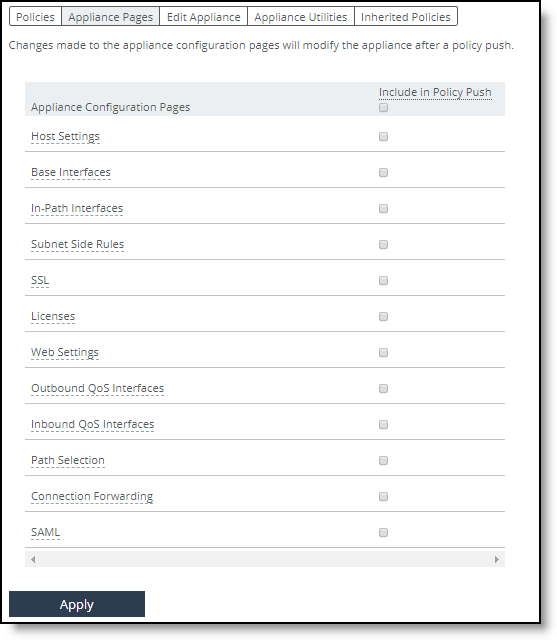
4. Select the name of the feature, such as Host Settings, to display the configuration settings you can configure or modify. On the right side of each feature appliance configuration pages is a list of applicable appliances.
Displaying appliance configuration pages
5. To configure features for the specified appliance directly from this page, complete the configuration as described in this table.
Control | Description |
Editing Appliance | Select the appliance you want to edit from the drop-down list. |
Page | Select the feature you want to configure from the drop-down list. |
Include/Exclude | Optionally either click Include to include this page in the policy push or click Exclude to exclude this page from the policy push. |
Page Applicable to | On the right side of the page is a list of applicable appliances and software restrictions. Make sure you have the correct product and software version installed—if you have a version mismatch you can’t push configuration changes to your appliances. |
Changes made to the appliance configuration settings are modified on the remote appliance after a policy push. When you perform a policy push, the SCC is the master configuration; any local changes made on SteelHeads are overwritten.
These sections describe each feature you can configure or modify in detail.
Managing host settings
You can edit host settings in the Editing Appliance Configuration: <hostname>, Host Settings page.
This page applies to SteelHead, SteelHead EX, and Interceptor.
To configure host settings
1. Choose Manage > Topology: Appliances to display the Appliances page.
2. Select the name of the appliance you want to edit to expand the page and display the Appliance tabs.
3. Select the Appliance Pages tab to display the Appliance Configuration Pages list.
4. Under Appliance Configuration Pages, click Host Settings to display the Editing Appliance Configuration: <hostname>, Host Settings page.
Managing host settings
5. Click Include or Exclude to include or exclude this configuration from the policy push for the specified appliance. Your changes aren’t applied to the specified appliance until the policy is pushed to the appliance.
6. Complete the configuration as described in this table.
Control | Description |
Hostname | Specify the hostname of the appliance. |
Apply | Applies your settings to the running configuration. |
Managing base interfaces
You can configure base interface settings in the Appliance Configuration: <hostname>, Base Interfaces page.
This page applies to SteelHead, SteelHead EX, and Interceptor.
When you initially ran the configuration wizard, you set required settings for the base interfaces for the SteelHeads. Only use the controls on this page if you require modifications or additional configuration:
•Primary Interface - On the appliance, the primary interface is the port you connect to the LAN switch. The primary interface is the appliance management interface. You connect to the primary interface to use the Management Console or the CLI.
•Auxiliary Interface - On the appliance, the auxiliary interface is an optional port you can use to connect the appliance to a non-Riverbed network management device. The IP address for the auxiliary interface must be on a subnet different from the primary interface subnet.
•Main Routing Table - Displays a summary of the main routing table for the appliance. If necessary, you can add static routes that might be required for out-of-path deployments or particular device management subnets.
To configure base interface settings
1. Choose Manage > Topology: Appliances to display the Appliances page.
2. Select the name of the appliance you want to edit to expand the page and display the Appliance tabs.
3. Select the Appliance Pages tab to display the Appliance Configuration Pages list.
4. Under Appliance Configuration Pages, click Base Interfaces to display the Editing Appliance Configuration: <hostname>, Base Interfaces page.
Editing the primary interface
5. Click Include or Exclude to include or exclude this configuration from the policy push for the specified appliance. Your changes aren’t applied to the specified appliance until the policy is pushed to the appliance.
6. Under Primary Interface, complete the configuration as described in this table.
Control | Description |
Enable Primary Interface | Enables the appliance management interface, which can be used for both managing the SteelHead and serving data for a server-side out-of-path (OOP) configuration. |
Obtain IPv4 Address Automatically | Select this option to automatically obtain the IP address from a DHCP server. A DHCP server must be available so that the system can request the IP address from it. Note: The primary and in-path interfaces can share the same network subnet. The primary and auxiliary interfaces can’t share the same network subnet. |
Enable IPv4 Dynamic DNS | Select this option to send the hostname with the DHCP request for registration with Dynamic DNS. The hostname is specified in the Networking > Networking: Host Settings page. |
Specify IPv4 Address Manually | Select this option if you don’t use a DHCP server to set the IPv4 address. Specify these settings: •IPv4 Address - Specify an IP address. •IPv4 Subnet Mask - Specify a subnet mask. •Default IPv4 Gateway - Specify the default gateway IPv4 address. The default gateway must be in the same network as the primary interface. You must set the default gateway for in-path configurations. |
Do Not Assign An IPv4 Address | Enables the interface without assigning an IP address. Use this option if all traffic on this interface is for VSP. |
Specify IPv6 Address Manually | Select this option and specify these settings to set an IPv6 address. •IPv6 Address - Specify an IP address using this format: eight 16-bit hexadecimal strings separated by colons, 128-bits. For example: 2001:38dc:0052:0000:0000:e9a4:00c5:6282 You don’t need to include leading zeros. For example: 2001:38dc:52:0:0:e9a4:c5:6282 You can replace consecutive zero strings with double colons (::). For example: 2001:38dc:52::e9a4:c5:6282 •IPv6 Prefix - Specify a prefix. The prefix length is 0 to 128, separated from the address by a forward slash (/). In this example, 60 is the prefix: 2001:38dc:52::e9a4:c5:6282/60 •IPv6 Gateway - Specify the gateway IP address. The gateway must be in the same network as the primary interface. Note: You can’t set an IPv6 address dynamically using a DHCP server. |
Speed and Duplex | •Speed - Select a speed from the drop-down list. The default value is Auto. •Duplex - Select Auto, Full, or Half from the drop-down list. The default value is Auto. If your network routers or switches don’t automatically negotiate the speed and duplex, be sure to set them manually. The speed and duplex must match (LAN and WAN) in an in-path configuration. If they don’t match, you might have a large number of errors on the interface when it is in bypass mode, because the switch and the router aren’t set with the same duplex settings. |
MTU | Specify the MTU value. The MTU is the largest physical packet size, measured in bytes, that a network can send. The default value is 1500. |
7. Under Auxiliary Interface, complete the configuration as described in this table.
Control | Description |
Enable Aux Interface | Enables an auxiliary interface, which can be used only for managing the SteelHead. It can’t be used for an out-of-path (OOP) SteelHead data service. Typically this is used for device-management networks. |
Obtain IPv4 Address Automatically | Select this option to automatically obtain the IP address from a DHCP server. A DHCP server must be available so that the system can request the IP address from it. Note: The primary and in-path interfaces can share the same subnet. The primary and auxiliary interfaces can’t share the same network subnet. |
Enable IPv4 Dynamic DNS | Select this option to send the hostname with the DHCP request for registration with Dynamic DNS. The hostname is specified in the Networking > Networking: Host Settings page. |
Specify IPv4 Address Manually | Select this option if you don’t use a DHCP server to set the IPv4 address. Specify these settings: •IPv4 Address - Specify an IP address. •IPv4 Subnet Mask - Specify a subnet mask. |
Do Not Assign An IPv4 Address | Enables the interface without assigning an IP address. Use this option if all traffic on this interface is for VSP. |
Specify IPv6 Address Manually | Select this option and specify these settings to set an IPv6 address. •IPv6 Address - Specify an IP address, using this format: eight 16-bit hexadecimal strings separated by colons, 128-bits. For example: 2001:38dc:0052:0000:0000:e9a4:00c5:6282 You don’t need to include leading zeros. For example: 2001:38dc:52:0:0:e9a4:c5:6282 You can replace consecutive zero strings with double colons (::). For example: 2001:38dc:52::e9a4:c5:6282 •IPv6 Prefix - Specify a prefix. The prefix length is 0 to 128, separated from the address by a forward slash (/). In this example, 60 is the prefix: 2001:38dc:52::e9a4:c5:6282/60 Note: You can’t set an IPv6 address dynamically using a DHCP server. |
Speed and Duplex | •Speed - Select the speed from the drop-down list. The default value is Auto. •Duplex - Select Auto, Full, or Half from the drop-down list. The default value is Auto. If your network routers or switches don’t automatically negotiate the speed and duplex, be sure to set them on the device manually. The speed and duplex must match (LAN and WAN) in an in-path configuration. To avoid a speed and duplex mismatch, configure your LAN external pair to match the WAN external pair. |
MTU | Specify the MTU value. The MTU is the largest physical packet size, measured in bytes, that a network can send. The default value is 1500. |
8. Click Apply to apply your changes to the running configuration.
Under the Main IPv4 Routing table, you can configure a static routing in the main routing table for out-of-path deployments or if your device management network requires static routes.
To configure main IPv4 routing table
1. Under the Main IPv4 Routing Table, click + Add a New Route to expand the page.
Managing IPv4 routes
2. Complete the configuration as described in this table.
Control | Description |
Add a New Route | Displays the controls to add a route. |
Destination IPv4 Address | Specify the destination IP address. |
Gateway IPv4 Address | Specify the IP address for the gateway. The gateway must be in the same network as the in-path interface. |
Interface | Specify the interface for the IPv4 route from the drop-down list. |
Add | Adds the route to the table list. |
Remove Selected | Select the check box next to the name and click Remove Selected. |
You can configure a static routing in the main routing table for out-of-path deployments or if your device management network requires static routes.
To configure main IPv6 routing table
1. Under the Main IPv6 Routing Table, click + Add a New Route to expand the page.
Adding IPv6 routing table
2. Complete the configuration as described in this table.
Control | Description |
Add a New Route | Displays the controls for adding a new route. |
Destination IPv6 Address | Specify the destination IP address. |
IPv6 Prefix | Specify a prefix. The prefix length is from 0 to 128 bits, separated from the address by a forward slash (/). |
Gateway IPv6 Address | Specify the IP address for the gateway. The gateway must be in the same network as the primary or auxiliary interface you’re configuring. |
Interface | Select an interface for the IPv6 route from the drop-down list. |
Add | Adds the route to the table list. |
Remove Selected | Select the check box next to the name and click Remove Selected. |
Managing in-path interface settings
You can edit in-path interface settings in the Editing Appliance Configuration: <hostname>, In-Path Interfaces page.
You configure in-path interfaces for deployments where the SCC is in the direct path (the same subnet) as the client and the server in your network. You also set the in-path gateway (WAN router).
In the Riverbed system, appliances have a unique in-path interface for each pair of LAN/WAN ports. For each appliance, the SCC detects LAN/WAN pairs, including those added through bypass cards, and identifies them according to slot (for example, inpath0_0, inpath0_1, inpath1_0, inpath1_1, and so on).
In the In-Path Interfaces page, you can clear either the IPv4 Address field or the IPv6 Address field, but not both. You must use the CLI to clear both addresses. Use the no interface <interface name> ip address and the no interface <interface name> ipv6 address <ipv6_addr> to clear both. For details, see the Riverbed Command-Line Interface Reference Manual.
For management interfaces, use the main routing table. For detailed information about the main routing table, see
“Managing base interfaces” on page 243.This page applies to SteelHead, SteelHead EX, and Interceptor.
To configure in-path interfaces
1. Choose Manage > Topology: Appliances to display the Appliances page.
2. Select the name of the appliance you want to edit to expand the page and display the Appliance tabs.
3. Select the Appliance Pages tab to display the Appliance Configuration Pages list.
4. Under Appliance Configuration Pages, click In-Path Interfaces to display the Editing Appliance Configuration: <hostname>, In-Path Interfaces page.
Displaying the in-path interfaces page
5. To enable link state propagation, under In-Path Settings, complete the configuration as described in this table.
Control | Description |
Enable Link State Propagation | Enables this control to shorten the recovery time of a link failure in physical in-path deployments. Link state propagation (LSP) communicates link status between the devices connected to the SteelHead. When you enable this LSP, RiOS monitors the link state of each SteelHead LAN-WAN pair. If either physical port loses link status, the corresponding interface disconnects, blocking the link. This control allows a link failure to quickly propagate through a chain of devices. If the link recovers, the SteelHead restores the corresponding interface automatically. LSP is enabled by default. Note: You can’t reach a MIP interface when LSP is also enabled and the corresponding in-path interface fails. •SteelHead (in the cloud) models don’t support LSP. •SteelHead (virtual edition) appliances running RiOS 8.0.3 and later with ESXi 6.5 using a Riverbed NIC card support LSP. These SteelHead (virtual edition) appliance configurations don’t support LSP: •SteelHead-v models running ESX/ESXi 4.0 or 4.1 •SteelHead-v models running RiOS 8.0.2 or earlier |
6. Select the interface that you want to edit to expand the page.
Configuring in-path interfaces
7. Complete the configuration as described in this table.
Control | Description |
IPv4 Address | Specify an IP address. This IP address is the in-path main interface. Note: In the In-Path Interfaces page, you can clear either the IPv4 Address field or the IPv6 Address field, but not both. You must use the CLI to clear both addresses. Use the no interface <interface name> ip address and the no interface <interface name> ipv6 address <ipv6_addr> to clear both. For details, see the Riverbed Command-Line Interface Reference Manual. |
IPv4 Subnet Mask | Specify the subnet mask. |
In-Path Gateway IP | Specify the IP address for the in-path gateway. If you have a router (or a Layer-3 switch) on the LAN side of your network, specify this device as the in-path gateway. Note: If there is a routed network on the LAN-side of the in-path appliance, the router that’s the default gateway for the appliance must not have the ACL configured to drop packets from the remote hosts as its source. The in-path appliance uses IP masquerading to appear as the remote server. |
Specify IPv6 Address Manually | Select this check box to assign an IPv6 address. IPv6 addresses are disabled by default. You can only assign one IPv6 address per in-path interface. Note: The primary and in-path interfaces can share the same subnet. The primary and auxiliary interfaces can’t share the same network subnet. |
IPv6 Address | Specify a global or site-local IPv6 address. This IP address is the in-path main interface. You can’t use a DHCP server to assign an IPv6 address automatically. Note: In the In-Path Interfaces page, you can clear either the IPv4 Address field or the IPv6 Address field, but not both. You must use the CLI to clear both addresses. Use the no interface <interface name> ip address and the no interface <interface name> ipv6 address <ipv6_addr> to clear both. For details, see the Riverbed Command-Line Interface Reference Manual. |
IPv6 Prefix | Specify the prefix. The prefix length is 0 to 128 bits, separated from the address by a forward slash (/). In this example, 60 is the prefix: 2001:38dc:52::e9a4:c5:6282/60 |
IPv6 Gateway | Specify the IPv6 address for the in-path gateway. You can use a link local address. If you have a router (or a Layer-3 switch) on the LAN side of your network, specify this device as the in-path gateway. Note: If there is a routed network on the LAN-side of the in-path appliance, the router that’s the default gateway for the appliance must not have the ACL configured to drop packets from the remote hosts as its source. The in-path appliance uses IP masquerading to appear as the remote server. |
LAN Speed and Duplex WAN Speed and Duplex | •Speed - Select Auto, 1000, 100, or 10 from the drop-down list. The default value is Auto. •Duplex - Select Auto, Full, or Half from the drop-down list. The default value is Auto. If your network routers or switches don’t automatically negotiate the speed and duplex, be sure to set them on the device manually. The speed and duplex must match (LAN and WAN) in an in-path configuration. To avoid a speed and duplex mismatch, configure your LAN external pair to match the WAN external pair. Note: Speed and duplex mismatches can easily occur in a network. For example, if one end of the link is set at half duplex or full duplex and the other end of the link is configured to autonegotiate (auto), the link defaults to half duplex, regardless of the duplex setting on the nonautonegotiated end. This duplex mismatch passes traffic, but it causes interface errors and results in degraded optimization. These guidelines can help you avoid speed and duplex mismatches when configuring the SteelHead: •Routers are often configured with fixed speed and duplex settings. Check your router configuration and set it to match the SteelHead WAN and LAN settings. Make sure that your switch has the correct setting. •After you finish configuring the SteelHead, check for speed and duplex error messages (cyclic redundancy check (CRC) or frame errors) in the System Log page of the Management Console. •If there is a serious problem with the SteelHead and it goes into bypass mode (that’s, it automatically continues to pass traffic through your network), a speed and duplex mismatch might occur when you reboot the SteelHead. To avoid a speed and duplex mismatch, configure your LAN external pair to match the WAN external pair. |
MTU | Specify the MTU value. The MTU is the largest physical packet size, measured in bytes, that a network can send. Applies to optimized traffic only. The default value is 1500. |
VLAN Tag ID | Specify the VLAN tag that the appliance uses to communicate with other SteelHeads in your network. The VLAN Tag ID might be the same value or a different value than the VLAN tag used on the client. A zero (0) value specifies nontagged (or native VLAN) and is the correct setting if there are no VLANs present. As an example, if the in-path interface is 192.168.1.1 in VLAN 200, you would specify tag 200. When the SteelHead communicates with a client or a server, it uses the same VLAN tag as the client or the server. If the SteelHead can’t determine which VLAN the client or server is in, it doesn’t use the VLAN tag (assuming that there is no router between the SteelHead and the client or server). You must also define in-path rules to apply to your VLANs. |
8. Under Management Interface <hostname>, modify the configuration as described in this table.
Control | Description |
Enable Appliance Management on This Interface | Enables a secondary MIP interface that you can reach through the physical in-path LAN and WAN interfaces. Configuring a secondary MIP interface allows management of SteelHeads from a private network while maintaining a logical separation of network traffic. Note: If LSP or fail-to-block is enabled, a message reminds you to disable the feature before enabling the MIP interface. |
IPv4 Address | Specify the IP address for the MIP interface. |
IPv4 Subnet Mask | Specify the subnet mask. |
Specify IPv6 Address | Enables IPv6 support on this interface. |
IPv6 Address | Specify the IPv6 address. |
IPv6 Prefix | Specify the prefix. The prefix length is 0 to 128 bits, separated from the address by a forward slash (/). In this example, 60 is the prefix: 2001:38dc:52::e9a4:c5:6282/60 |
VLAN Tag ID | Specifies a numeric VLAN Tag ID. When you specify the VLAN Tag ID for the MIP interface, all packets originating from the SteelHead from the MIP interface are tagged with that identification number. The VLAN Tag ID might be the same value or a different value than the in-path interface VLAN tag ID. The MIP interface could be untagged and the in-path interface could be tagged and vice versa. A zero (0) value specifies nontagged (or native VLAN) and is the correct setting if there are no VLANs present. For example, if the MIP interface is 192.168.1.1 in VLAN 200, you would specify tag 200. |
Managing subnet side rules
You configure subnet side rules in the Editing Appliance Configuration: <hostname>, Subnet Side Rules page.
You need to configure subnet side rules to support VSP and Flow Export on a virtual in-path deployment.
Subnet side rules enable you to configure subnets as LAN-side subnets or WAN-side subnets for a virtual in-path SteelHead appliance. The subnet side rules determine whether traffic originated from the LAN or the WAN-side of the SteelHead appliance based on the source subnet. You must configure subnets on each SteelHead appliance in a virtual in-path configuration, as the subnets for each will likely be unique.
With subnet side rules in place, RiOS can send incoming packets to the correct VSP VNIs for VVSP, and, a virtual in-path SteelHead can use flow export collectors such as NetFlow to analyze nonoptimized or passed through traffic correctly. Otherwise, the SteelHead appliance can’t discern whether the traffic is traveling from the LAN to the WAN or in the opposite direction. This can result in over-reporting traffic in a particular direction or for a particular interface.
FakeIndex is necessary for correct optimized traffic reporting. For details, see the Riverbed Deployment Guide.
Tip: You can’t delete the default rule, Default, which optimizes all remaining WAN-side traffic that hasn’t been selected by another rule. This rule is always listed last.
This page applies to SteelHead and SteelHead EX.
To configure subnet side rules settings
1. Choose Manage > Topology: Appliances to display the Appliances page.
2. Select the name of the appliance you want to edit to expand the page and display the Appliance tabs.
3. Select the Appliance Pages tab to display the Appliance Configuration Pages list.
4. Under Appliance Configuration Pages, click Subnet Side Rules to display the Editing Appliance Configuration: <hostname>, Subnet Side Rules page.
Editing the subnet side rules
5. Complete the configuration as described in this table.
Control | Description |
Add a Subnet Side Rule | Displays the controls to create a subnet side rule. |
Insert Rule At | Select Start, End, or a rule number from the drop-down list. SteelHead appliances evaluate rules in numerical order starting with rule 1. If the conditions set in the rule match, then the rule is applied, and the system moves on to the next packet. If the conditions set in the rule don’t match, the system consults the next rule. For example, if the conditions of rule 1 don’t match, rule 2 is consulted. If rule 2 matches the conditions, it is applied, and no further rules are consulted. |
Subnet | Specify the subnet. Use this format: <ip-address>/<subnet-mask> In SCC 9.8, this field also accepts IPv6 addresses. •IPv6 Address - Specify an IP address using this format: eight 16-bit hexadecimal strings separated by colons, 128-bits. For example: 2001:38dc:0052:0000:0000:e9a4:00c5:6282 You don’t need to include leading zeros. For example: 2001:38dc:52:0:0:e9a4:c5:6282 You can replace consecutive zero strings with double colons (::). For example: 2001:38dc:52::e9a4:c5:6282 •IPv6 Prefix - Specify a prefix. The prefix length is 0 to 128, separated from the address by a forward slash (/). In this example, 60 is the prefix: 2001:38dc:52::e9a4:c5:6282/60 |
Subnet is on the LAN side of this appliance | In virtual in-path configurations, all traffic is flowing in and out of one physical interface. Select to specify that the subnet is on the LAN side of the device. |
Subnet is on the WAN side of this appliance | In virtual in-path configurations, all traffic is flowing in and out of one physical interface. Select to specify that the subnet is on the WAN side of the device. |
Add | Adds the rule to the subnet map table. The Management Console redisplays the subnet map table and applies your changes to the running configuration, which is stored in memory. |
Remove Subnet Rules | Select the check box next to the name and click Remove Subnet Rules. |
Managing SSL settings
You configure SSL settings for a specific appliance in the Editing Appliance Configuration: <hostname>, SSL page.
SSL is a cryptographic protocol that provides secure communications between two parties over the Internet. Typically in a web-based application, it is the client that authenticates the server. To identify itself, an SSL certificate is installed on a web server and the client checks the credentials of the certificate to make sure it is valid and signed by a trusted third party. Trusted third parties that sign SSL certificates are called certificate authorities (CA).
This page applies to SteelHead and SteelHead EX.
For detailed information, see the SteelHead User Guide for SteelHead CX.
To display SSL tabs
1. Choose Manage > Topology: Appliances to display the Appliances page.
2. Select the name of the appliance you want to edit to expand the page and display the Appliance tabs.
3. Select the Appliance Pages tab to display the Appliance Configuration Pages list.
4. Under Appliance Configuration Pages, click SSL to display the Editing Appliance Configuration: <hostname>, SSL page.
Editing SSL setting
s
5. To display certificates PLM, replace certificates, or generate CSR, click the tab to expand the page and display configuration settings.
Displaying the certificate PEM
You can display the certificate PEM for the selected appliance in the Editing Appliance Configuration: <hostname>, SSL page.
To view peering certificate details
1. Choose Manage > Topology: Appliances to display the Appliances page.
2. Select the name of the appliance you want to edit to expand the page and display the Appliance tabs.
3. Select the Appliance Pages tab to display the Appliance Configuration Pages list.
4. Under Appliance Configuration Pages, click SSL to display the Editing Appliance Configuration: <hostname>, SSL page.
5. Select the Display Certificate PEM tab to display the certificate in PEM format.
Replacing the SSL certificate
You can replace SSL certificates for the selected appliance in the Editing Appliance Configuration: <hostname>, SSL page.
To replace the SSL certificate
1. Choose Manage > Topology: Appliances to display the Appliances page.
2. Select the name of the appliance you want to edit to expand the page and display the Appliance tabs.
3. Select the Appliance Pages tab to display the Appliance Configuration Pages list.
4. Under Appliance Configuration Pages, click SSL to display the Editing Appliance Configuration: <hostname>, SSL page.
5. Select the Replace Certificate tab to expand the page.
Replacing a certificate
6. Complete the configuration as described in this table.
Control | Description |
Import Certificate and Private Key | Imports the certificate and key. The page displays controls for browsing to and uploading the certificate and key files. You can also use the text box to copy and paste a PEM file. The private key is required regardless of whether you’re adding or updating the certificate. |
Certificate | •Upload - Browse to the local file in PKCS-12, PEM, or DER formats. •Paste it here (PEM) - Copy and then paste the contents of a PEM file. |
Private Key | Select the private key origin. •The Private Key is in a separate file (see below) - You can either upload it or copy and paste it. •This file includes the Certificate and Private Key •The Private Key for this Certificate was created with a CSR generated on this appliance |
Separate Private Key | •Upload (PEM or DER formats) - Browse to the local file in PEM or DER formats. •Paste it here (PEM only) - Paste the contents of a PEM file. •Decryption Password - Specify the decryption password, if necessary. Passwords are required for PKCS-12 files, optional for PEM files, and never needed for DER files. |
Import Certificate and Key | Imports the certificate and key. |
Generate Self-Signed Certificate and New Private Key | Select this option to generate a new private key and self-signed public certificate. The page displays controls to identify and generate the new certificate and key. |
Common Name - Specify the common name of a certificate. To facilitate configuration, you can use wildcards in the name: for example, *.example.com. If you have three origin servers using different certificates, such as webmail.example.com, internal.example.com, and marketingweb.example.com, on the server-side SteelHeads, all three server configurations can use the same certificate name *.example.com. |
Organization Name - Specify the organization name (for example, the company). |
Organization Unit Name - Specify the organization unit name (for example, the section or department). |
Locality - Specify the city. |
State (no abbreviations) - Specify the state. |
Country (2-letter code) - Specify the country (2-letter code only). |
Email Address - Specify the email address of the contact person. |
Validity Period (Days) - Specify how many days the certificate is valid. |
Private Key | Cipher Bits - Select the key length from the drop-down list. The default is 1024. |
Generate Certificate and Key | Generates certificate and key. |
Generating the certificate signing request (CSR)
You can generate the CSR for the selected appliance in the Editing Appliance Configuration: <hostname>, SSL page.
To generate the CSR
1. Choose Manage > Topology: Appliances to display the Appliances page.
2. Select the name of the appliance you want to edit to expand the page and display the Appliance tabs.
3. Select the Appliance Pages tab to display the Appliance Configuration Pages list.
4. Under Appliance Configuration Pages, click SSL to display the Editing Appliance Configuration: <hostname>, SSL page.
5. Select the Generate CSR tab to expand the page.
Generating the CSR
6. Complete the configuration as described in this table.
Control | Description |
Common Name (required) | Specify the common name (hostname) of the peer. |
Organization Name | Specify the organization name (for example, the company). |
Organization Unit Name | Specify the organization unit name (for example, the section or department). |
Locality | Specify the city. |
State | Specify the state. Don’t abbreviate. |
Country (2-letter code) | Specify the country (2-letter code only). |
Email Address | Specify the email address of the contact person. |
Generate CSR | Generates the Certificate Signing Request. |
Managing licenses
You can add and view licenses for the specified appliance in the Editing Appliance Configuration: <hostname>, Licenses page.
The SCC doesn’t edit or delete licenses for a SteelHead, it can only add new license keys.
This page applies to SteelHead, SteelHead EX, and Interceptor.
For details, see the SteelHead User Guide for SteelHead CX.
To view licenses
1. Choose Manage > Appliances to display the Appliances page.
2. Select the name of the appliance you want to edit to display the Edit Appliance tab.
3. Select the Appliance Pages tab to display the Appliance Pages tab.
4. Under Appliance Configuration Pages, click Licenses to display the Editing Appliance Configuration <hostname>, Licenses page.
Adding licenses
5. Complete the configuration as described in this table.
Controls | Descriptions |
Add a New License | Displays the controls for adding a new license. |
Text box | Type or paste the license into the text area. |
Add | Adds the new license. |
Remove Selected | Select the check box next to the name and click Remove Selected. |
Managing web settings and web certificates
You configure web settings and web certificates in the Editing Appliance Configuration: <hostname>, Web Settings page.
This page applies to SteelHead, SteelHead EX, and Interceptor.
For details, see the SteelHead User Guide for SteelHead CX.
To configure web settings
1. Choose Manage > Topology: Appliances to display the Appliances page.
2. Select the name of the appliance you want to edit to display the Edit Appliance tab.
3. Select the Appliance Pages tab to display the Appliance Configuration Pages list.
4. Under Appliance Configuration Pages, click Web Settings to display the Editing Appliance Configuration <hostname>, Web Settings page.
Managing web settings
5. Under Web Settings, complete the configuration as described in this table.
Control | Description |
Default Web Login ID | Specify the username that appears in the authentication page. The default value is admin. |
Web Inactivity Timeout | Specify the number of idle minutes before time-out. The default value is 15. A value of 0 disables time-out. |
Allow Session Timeouts When Viewing Auto-Refreshing Pages | By default, session time-out is enabled, which stops the automatic updating of the report pages when the session times out. Clear the Allow box to disable the session time-out, remain logged in indefinitely, and automatically refresh the report pages. Note: Disabling this feature poses a security risk. |
6. Click Apply to apply your changes to the running configuration.
Managing web certificates
You can manage web certificates in the Web Settings page:
•View certificate details.
•View certificate in PEM format.
•Replace a signed certificate by importing a certificate and private key or generating a self-signed certificate and new private key.
•Generate a certificate signing request (CSR).
To manage web certificates
1. Under Web Certificate, select the Details tab.
The identity certificate details appear, as described in this table.
Control | Description |
Issued To/Issued By | Common Name - Specifies the common name of the certificate authority. |
Email - Specifies the email. |
Organization - Specifies the organization name (for example, the company). |
Organization Unit - Specifies the organization unit name (for example, section or department). |
Locality - Specifies the city. |
State - Specifies the state. |
Country - Specifies the country. |
Validity | Issued On - Specifies the date the certificate was issued. Expires On - Specifies the date the certificate expires. |
Fingerprint | Specifies the SSL fingerprint. |
Key | Type - Specifies the key type. Size - Specifies the size, in bytes. |
2. To view the certificate in PEM format, under Web Certificate, select the PEM tab to display the certificate. The certificate appears in PEM format.
3. To replace an existing certificate, under Web Certificate, click Replace and complete the configuration as described in this table.
Control | Description |
Import Certificate and Private Key | Imports the certificate and key. The page displays controls for browsing to and uploading the certificate and key files. You can also use the text box to copy and paste a PEM file. The private key is required regardless of whether you’re adding or updating the certificate. |
Certificate | Upload - Browse to the local file in PKCS-12, PEM, or DER formats. |
Paste it here (PEM) - Copy and then paste the contents of a PEM file. |
Private Key | Select the private key origin. •The Private Key is in a separate file (see below) - You can either upload it or copy and paste it. •This file includes the Certificate and Private Key •The Private Key for this Certificate was created with a CSR generated on this appliance |
Separate Private Key | Upload (PEM or DER formats) - Browse to the local file in PEM or DER formats. |
Paste it here (PEM only) - Paste the contents of a PEM file. |
Decryption Password - Specify the decryption password, if necessary. Passwords are required for PKCS-12 files, optional for PEM files, and never needed for DER files. |
Import Certificate and Key | Imports the certificate and key. |
Generate Self-Signed Certificate and New Private Key | Select this option to generate a new private key and self-signed public certificate. The page displays controls to identify and generate the new certificate and key. |
Organization Name - Specify the organization name (for example, the company). |
Organization Unit Name - Specify the organization unit name (for example, the section or department). |
Locality - Specify the city. |
State (no abbreviations) - Specify the state. |
Country (2-letter code) - Specify the country (2-letter code only). |
Email Address - Specify the email address of the contact person. |
Validity Period (Days) - Specify how many days the certificate is valid. |
Private Key | Cipher Bits - Select the key length from the drop-down list. The default is 1024. |
Generate Certificate and Key | Generates CSR and private key. |
4. To generate a CSR, under Web Certificate click Generate CSR and complete the configuration as described in this table.
Control | Description |
Common Name | Specify the common name (hostname). |
Organization Name | Specify the organization name (for example, the company). |
Organization Unit Name | Specify the organization unit name (for example, the section or department). |
Locality | Specify the city. |
State | Specify the state. |
Country | Specify the country (two-letter code only). |
Email Address | Specify the email address of the contact person. |
Generate CSR | Generates the CSR. |
Managing outbound QoS interfaces
You configure legacy outbound QoS interfaces for Basic and Advanced QoS in the Editing Appliance Configuration: <hostname>. Outbound QoS Interfaces page.
This feature applies to SteelHead and SteelHead EX.
For detailed information about QoS, see the SteelHead User Guide for SteelHead CX.
To modify Outbound QoS (Basic) interface settings
1. Choose Manage > Topology: Appliances to display the Appliances page.
2. Select the name of the appliance you want to edit to display the Edit Appliance tab.
3. Select the Appliance Pages tab to display the Appliance Configuration Pages list.
4. Under Appliance Configuration Pages, click Outbound QoS Interfaces to display the Editing Appliance Configuration: <hostname>, Outbound QoS (Basic) page.
Outbound QoS basic interfaces
5. Under WAN Link, complete the configuration as described in this table.
Control | Description |
WAN Bandwidth (kbps) | Specify its bandwidth link rate in kilobits per second. The link rate is the bottleneck WAN bandwidth, not the interface speed out of the WAN interface into the router or switch. For example, if your SCC connects to a router with a 100-Mbps link, don’t specify this value; specify the actual WAN bandwidth (for example, T1 or T3). Different WAN interfaces can have different WAN bandwidths; you must enter the bandwidth link rate correctly for QoS to function properly. |
Interfaces detected on the Appliance | Select the necessary check boxes. |
Additional Interfaces | Select the necessary check boxes. |
6. Click Apply to apply your changes to the running configuration.
To modify outbound QoS (advanced) interface settings
1. Choose Manage > Topology: Appliances to display the Appliances page.
2. Select the name of the appliance you want to edit to display the Edit Appliance tab.
3. Select the Appliance Pages tab to display the Appliance Configuration Pages list.
4. Under Appliance Configuration Pages, select Outbound QoS Interfaces (Advanced) to display the Editing Appliance Configuration: <hostname>, Outbound QoS (Basic) page.
5. Click Outbound QoS (Advanced) to display the Editing Appliance Configuration: <hostname>, Outbound QoS page.
Modifying legacy outbound QoS advanced interfaces
6. Under WAN Link, complete the configuration as described in this table.
Control | Description |
Interfaces detected on the Appliance | Select the necessary check boxes. |
Additional Interfaces | Select the necessary check boxes. |
7. Click Apply to apply your changes to the running configuration.
Managing legacy inbound QoS interfaces
You configure legacy inbound QoS interfaces in the Editing Appliance Configuration: <hostname>. Outbound QoS Interfaces page.
This feature applies only to SteelHead and SteelHead EX.
For detailed information about QoS, see the SteelHead User Guide for SteelHead CX.
To modify inbound QoS interfaces
1. Choose Manage > Topology: Appliances to display the Appliances page.
2. Select the name of the appliance you want to edit to display the Edit Appliance tab.
3. Select the Appliance Pages tab to display the Appliance Configuration Pages list.
4. Under Appliance Configuration Pages, click Inbound QoS Interfaces to display the Editing Appliance Configuration: <hostname>, Inbound QoS Interfaces page.
Configuring legacy inbound QoS interfaces
5. Under WAN Link, complete the configuration as described in this table.
Control | Description |
WAN Bandwidth (kbps) | Specify WAN interface bandwidth link rate in kilobits per second. The link rate is the bottleneck WAN bandwidth, not the interface speed out of the WAN interface into the router or switch. For example, if your CMC appliance connects to a router with a 100-Mbps link, don’t specify this value; specify the actual WAN bandwidth (for example, T1 or T3). Different WAN interfaces can have different WAN bandwidths; you must enter the bandwidth link rate correctly for QoS to function properly. |
Interfaces detected on the Appliance | Select the necessary check box(es). |
Additional Interfaces | Select the necessary check box(es). |
6. Click Apply to apply your changes to the running configuration.
Managing path selection
You configure legacy path selection rules in the Editing Appliance Configuration: <hostname>, Path Selection page.
You can’t migrate your previously defined path selection rules to SCC 9.0 or later.
This page applies to SteelHead and SteelHead EX.
To add a new path
1. Choose Manage > Topology: Appliances to display the Appliances page.
2. Select the name of the appliance you want to edit to display the Edit Appliance tab.
3. Select the Appliance Pages tab to display the Appliance Configuration Pages list.
4. Under Appliance Configuration Pages, click Path Selection to display the Editing Appliance Configuration: <hostname>, Path Selection page.
5. Click + Add a New Path to expand the page.
Configuring legacy path selection rules
6. Complete the configuration as described in this table.
Control | Description |
Name | Specify the path selection name. Note: The path selection name is case sensitive and must match the path name in the policy being pushed to this appliance. If the names don’t match, policy push will fail. |
Gateway IP Address | Specify the IP address for the gateway. The gateway must be in the same network as the in-path interface. Note: The gateway IP address must be in the same subnet (local network) as the in-path interface. |
Interface | Select a relay interface over which the appliance reaches the path. |
Tunnel Mode | Select the tunnel mode from the drop-down list: None or GRE. GRE provides IPv4 generic routing encapsulation (GRE) for direct uplinks. Direct uplinks using GRE become direct tunneled uplinks. You must create direct tunneled uplinks to steer traffic over any uplink that traverses a stateful firewall between the SteelHeads. Without GRE, traffic attempting to switch midstream to an uplink that traverses a stateful firewall might be blocked. The firewall needs to track the TCP connection state and sequence numbers for security reasons. Because the firewall hasn’t logged the initial connection handshake, and has partial or no packet sequence numbers, it blocks the attempt to switch to the secondary uplink and might drop these packets. To traverse the firewall, path selection can encapsulate that traffic into a GRE tunnel. |
Add | Adds the path to the path table. The SCC redisplays the path table and applies your changes to the running configuration, that’s stored in memory. |
Remove Selected | Select the check box next to the name and click Remove Selected. |
Managing connection forwarding
You configure connection forwarding for a network with multiple paths from the server in the Editing Appliance Configuration: <hostname>, Connection Forwarding page.
You enable connection forwarding only in asymmetric networks; that is, networks in that a client request traverses a different network path than the server response. The default port for connection forwarding is 7850.
This feature applies to SteelHead and SteelHead EX.
For detailed information about connection forwarding, see the SteelHead User Guide for SteelHead CX.
To configure connection forwarding
1. Choose Manage > Topology: Appliances to display the Appliances page.
2. Select the name of the appliance you want to edit to display the Edit Appliance tab.
3. Select the Appliance Pages tab to display the Appliance Configuration Pages list.
4. Under Appliance Configuration Pages, click Connection Forwarding to display the Editing Appliance Configuration: <hostname>, Connection Forwarding page.
Configuring connection forwarding
5. Under Connection Forwarding Settings, complete the configuration as described in this table.
Control | Description |
Enable Connection Forwarding | Enables connection forwarding by default on all neighbors added to the peer list. The default value is 7850. |
Port | Specify the port number to use as the default for the neighbor SteelHead in-path port. The default value is 7850. |
Keep-Alive Interval | Specify the number of seconds to use as the default interval for ping commands between neighbor SteelHeads. The default value is 1 second. |
Keep-Alive Count | Specify the number of tries to use as the default number of failed ping attempts before an appliance terminates a connection with a neighbor. The default value is 3. |
In-Path Neighbor Failure | Uses the neighbor appliance to optimize new connections if the appliance fails. For in-path deployments that use connection forwarding with WCCP, enabling this option ensures that if one appliance fails, the neighbor appliance continues to optimize new connections. For in-path deployments that use connection forwarding without WCCP, enabling this option ensures that a SteelHead attempts to optimize new connections that are symmetrically routed, even after all of the neighbor SteelHeads on another network path failed. New asymmetrically routed connections aren’t optimized but passed through. |
Multiple Interface Support | Enables high availability on SteelHeads configured with multiple in-path interfaces and using connection forwarding with another multiport SteelHead. This option makes all neighbor in-path interface IP addresses visible to each peer to ensure proper neighbor communication if the in-path0_0 interface fails. RiOS 6.5 and later require connection forwarding in a WCCP cluster. You must enable multiple interface support for a connection-forwarding neighbor to work with IPv6. |
IPv6 Connection Forwarding | Enables IPv6 connection forwarding mode. Enabling this option disallows IPv4 addresses for neighbors. |
6. Under Neighbor Table, complete the configuration as described in this table.
Control | Description |
+ Add a New Neighbor | Displays the controls to add a new neighbor. |
Hostname | Specify a hostname. |
In-Path IP Address | Specify the in-path IP address for the neighbor SteelHead. When you define a neighbor, you must specify the appliance in-path IP address, not the primary IP address. Either IPv4 or both IPv4 and IPv6 can be specified. To use connection forwarding with IPv6, both SteelHeads must be running RiOS 8.5 or later and you must enable multiple interface support. |
Port | Specify the in-path port for the neighbor SteelHead. The default port is 7850. |
Additional IP Addresses | Adds a neighbor SteelHead to the neighbor list. |
Add | Adds a new neighbor. |
Remove Selected | Select the check box next to the name and click Remove Selected. |
Managing web proxy cache settings
You can configure the web proxy cache size for VCX-10 to VCX-90 SteelHeads in the Editing Appliance Configuration: <hostname>, Web Proxy Settings page.
You can configure the total cache size in the SCC Web Proxy Settings page for the managed VCX-10 to VCX-90 models.
If you make a change to the web proxy cache size and web proxy is running, the web proxy is automatically restarted.
Any changes to an already configured web proxy cache size will purge the cache. We recommend that you make changes to the web proxy cache size cautiously.
Disabling web proxy on VCX models will disable all web proxy alarms but it will not affect the existing cache.
This feature applies only to SteelHead VCX-10 to VCX-90 models.
For best practices, see “Web proxy on VCX models” on page 40.
For detailed information about web proxy, see Managing web proxies and the SteelHead User Guide for SteelHead CX.
To configure web proxy cache settings
1. Choose Manage > Topology: Appliances to display the Appliances page.
2. Select the VCX appliance you want to edit to display the Edit Appliance tab.
3. Select the Appliance Pages tab to display the Appliance Configuration Pages list.
4. Under Appliance Configuration Pages, click Web Proxy Settings to display the Editing Appliance Configuration: <hostname>, Web Proxy Cache Settings page.
Configuring web proxy cache settings
5. Under Web Proxy Cache Settings, complete the configuration as described in this table.
Control | Description |
Min. Cache Size | The minimum web proxy cache size in gigabytes (GBs), as specified by the license. The minimum cache size is 5 GBs. This value is updated after a policy push or a change is detected in the license. |
Max. Cache Size | Specify the maximum cache size in gigabytes (GBs), as specified by the license. This value is updated after a policy push or a change is detected in the license. The maximum cache size is 800 GBs, depending on the available disk size and your license maximum size. The maximum cache size can’t exceed the available disk space. If you exceed the available disk space, an alarm is triggered. |
Actual Cache Size | The disk space used by the current web proxy cache. This value is updated after a policy push or a change is detected in the license. The actual disk size differs if the cache size isn’t configured or if the disk doesn’t have enough disk space for the configured cache size. |
Cache Size | Specify the total cache size in gigabytes (GBs). This value is your configured cache size. If the configured cache size is larger than what the management disk can support (that is, the actual cache size) then an alarm is raised. |
Apply | Applies your settings. |
Managing SteelFusion Core settings
You configure connection forwarding for a network with multiple paths from the server in the Editing Appliance Configuration: <hostname>, SteelFusion Settings page.
The SteelFusion Core product name has changed to SteelFusion Core. You might see the old and new names in the SCC.
This feature applies to SteelHead EX.
For detailed information about SteelFusion Core, see the SteelFusion Core User Guide.
To modify SteelFusion settings
1. Choose Manage > Topology: Appliances to display the Appliances page.
2. Select the name of the appliance you want to edit to display the Edit Appliance tab.
3. Select the Appliance Pages tab to display the Appliance Configuration Pages list.
4. Under Appliance Configuration Pages, click SteelFusion Settings to display the Editing Appliance Configuration: <hostname> SteelFusion Settings page.
5. Under SteelFusion Core Settings, complete the configuration as described in this table.
Control | Description |
Connect to a SteelFusion Core | Enables SteelFusion Core settings. |
Hostname/IP | Specify the hostname of the SteelFusion Core. The SteelFusion Core identifier is case-sensitive. |
SteelFusion Edge Identifier | Specify a value by that the current appliance device can be recognized by the SteelFusion Core. You may use any value. For example, the hostname of the device. Note: The SteelHead EX must be licensed. If failover is configured, both appliances must use the same self-identifier. In this case, you can use a value that represents the group of appliances. For detailed information, see the SteelHead User Guide for SteelHead EX. |
Port | Specify the port number for the SteelFusion Core. The default value is 7970. |
Local interface | Select the local interface from the drop-down list. The default value is primary. |
Connect to an active SteelFusion Edge as Standby Peer for High Availability | Enables SteelFusion Edge settings. High Availability speeds up pass-through traffic handling. |
SteelFusion Edge Serial Number | Specify the SteelFusion Edge serial number. |
SteelFusion Edge Identifier | Specify a value by that the current appliance device can be recognized by the SteelFusion Edge. |
SteelFusion Edge IP Address | Specify the SteelFusion Edge IP address. A legal IPv4 address (xxx.xxx.xxx.xxx) is required. |
Interface | Select the interface from the drop-down list. The default value is primary. |
Alternate SteelFusion Edge IP Address | Specify the SteelFusion Edge IP address. A legal IPv4 address (xxx.xxx.xxx.xxx) is required. |
Alternate Interface | Select an alternate interface from the drop-down list. The default value is primary. |
Interface to SteelFusion Core | Select the interface to SteelFusion Core from the drop-down list. The default value is primary. |
Apply | Click Apply to complete the SteelFusion Core configuration. |
Managing Virtual Services Platform
You configure connection forwarding for a network with multiple paths from the server in the Editing Appliance Configuration: <hostname>, Virtual Services Platform page.
This feature applies to SteelHead EX.
To modify virtual services platform
1. Choose Manage > Topology: Appliances to display the Appliances page.
2. Select the name of the appliance you want to edit to display the Appliance Pages tab.
3. Select the Appliance Pages tab to display the Appliance Configuration Pages list.
4. Under Appliance Configuration Pages, click Virtual Services Platform to display the Editing Appliance Configuration: <hostname>, Virtual Services Platform page.
Configuring virtual services platform
5. Select the ESXI management interface from the drop-down list.
6. Under vmk1 (ESXi primary), complete the configuration as described in this table.
Control | Description |
Enable Interface | Enables vmk1 (ESXi primary) interface. |
Obtain IPv4 Address Automatically | Select this option to automatically obtain the IP address from a DHCP server. A DHCP server must be available so that the system can request the IP address from it. The primary and in-path interfaces can share the same network subnet, but the primary and auxiliary interfaces can’t share the same network subnet. •Enable IPv4 DHCP DNS - Select this option to enable IPv4 DHCP DNS option. |
Specify IPv4 Address Manually | Select this option if you don’t use a DHCP server to set the IPv4 address. Specify these settings: •IPv4 Address - Specify an IP address. •IPv4 Subnet Mask - Specify a subnet mask. |
7. Under vmk2 (ESXi aux), complete the configuration as described in this table.
Control | Description |
Enable Interface | Enables vmk2 (ESXi aux) interface. |
Obtain IPv4 Address Automatically | Select this option to automatically obtain the IP address from a DHCP server. A DHCP server must be available so that the system can request the IP address from it. The primary and in-path interfaces can share the same network subnet, but the primary and auxiliary interfaces can’t share the same network subnet. •Enable IPv4 DHCP DNS - Select this option to enable IPv4 DHCP DNS option. |
Specify IPv4 Address Manually | Select this option if you don’t use a DHCP server to set the IPv4 address. Specify these settings: •IPv4 Address - Specify an IP address. •IPv4 Subnet Mask - Specify a subnet mask. •Gateway - Specify the gateway. |
Apply | Click Apply to apply your changes to the running configurations. |
Managing data interfaces
You configure connection forwarding for a network with multiple paths from the server in the Editing Appliance Configuration: <hostname>, Data Interfaces page.
This feature applies to SteelHead EX.
To manage data interfaces
1. Choose Manage > Topology: Appliances to display the Appliances page.
2. Select the name of the appliance you want to edit to display the Edit Appliance tab.
3. Select the Appliance Pages tab to display the Appliance Configuration Pages list.
4. Under Appliance Configuration Pages, click Data Interfaces to display the Editing Appliance Configuration: <hostname>, Data Interfaces page.
Configuring data interfaces
5. Under Interfaces detected on the Appliance, complete the configuration as described in this table.
Control | Description |
Additional Interfaces | Specify any additional interfaces. |
Apply | Applies the additional interfaces. |
Managing SAML
You can enable SAML on a single appliance using the SAML page of that appliance, or you can configure SAML in a policy and then push the policy across multiple appliances.
Before you enable SAML on a single appliance or on multiple appliances, you must configure IdP individually for each appliance because the IdP metadata required to enable SAML is unique for each appliance.
Basic steps to configure SAML as a policy
Task | Reference |
1. Download the metadata of the appliance from the appliance’s management console. | SteelHead User Guide |
2. Configure the appliance in the IdP website. | SteelHead User Guide |
3. Paste the metadata you received from the IdP website in the SCC Management Console. Optionally, if you want to check whether your IdP configuration is valid or not, paste the metadata in the appliance’s Management Console instead. After you validate the metadata, fetch the appliance-specific configuration from SCC. |
SteelHead User Guide and
|
4. Repeat steps 1 through 3 for all the appliances on which you want to perform the policy push. | |
5. Configure SAML in the policy pages and push the policy across all the appliances. | |
For detailed information, see the SteelHead User Guide.
Configuring IdP in SCC
You can configure IdP in the Editing Appliance Configuration: <hostname>, SAML page.
To configure IdP of a SteelHead in SCC
1. Choose Manage > Topology: Appliances to display the Appliances page.
2. Select the name of the appliance you want to edit to display the Appliance Pages tab.
3. Select the Appliance Pages tab to display the Appliance Configuration Pages list.
4. Under Appliance Configuration Pages, click SAML to display the Editing Appliance Configuration: <hostname>, SAML page.
Configuring IdP
5. Click Include to include this configuration from the policy push for the specified appliance. Your changes aren’t applied to the specified appliance until the policy is pushed to the appliance.
6. Under IdP Configuration, paste the IdP metadata you received from the IdP website.
7. Click Apply.
8. Click Save to Disk to save you settings permanently.
You have completed IdP configuration that is specific to an appliance.
You can now create a policy to configure and enable SAML. This policy can be pushed to an appliance of your choice or to a group of appliances.
Creating a SAML authentication policy
To configure SAML in a policy
1. Choose Manage > Policies to display the Policies page.
Policies page
2. Click +Add Policy to expand the page.
3. Type a policy name and description and click Add to display the Editing Policy page.
4. Click + Add/Remove Pages to display the Add/Remove Policy Pages pop-up window.
5. Under Security, select SAML and click Apply to display the Editing Policy page.
Adding SSL settings to a policy
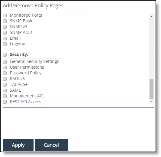
6. In the Editing Policy page, click SAML to display Editing <policy-name> page.
7. Click Include to include the policy in the policy push.
Editing the policy
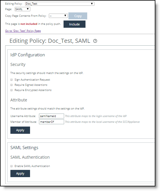
8. Under IdP Configuration, configure the SAML request and response settings as described in this table.
Control | Description |
IdP Metadata | Paste the IdP metadata you copied or received from the IdP website. |
Security Settings | Sign Authentication Request - Select this option to have SCC sign the SAML authentication request sent to the identity provider. Signing the initial login request sent by SCC allows the identity provider to verify that all login requests originate from a trusted service provider. |
Requires Signed Assertions - Select if SAML assertions must be signed. Some SAML configurations require signed assertions to improve security. |
Requires Encrypted Assertions - Select this option to indicate to the SAML identity provider that SCC requires encrypted SAML assertion responses. When this option is selected, the identity provider encrypts the assertion section of the SAML responses. Even though all SAML traffic to and from SCC is already encrypted by the use of HTTPS, this option adds another layer of encryption. |
Attribute | User Name Attribute - Enter the name of the IdP variable that carries the username of the user. The username attribute is mandatory and must be sent by your identify provider in the SAML response to align the login with a configured SteelHead account. The default value is samlNameId. |
Member of Attribute - Enter the name of the IdP variable that carries the role of the user. The default value is memberOf. |
9. Click Apply to save your configuration settings.
10. Under SAML, to enable SAML, select the Enable SAML check box and click Apply.
11. Click Save to Disk to save you settings permanently.
12. Choose Manage > Topology: Appliances to return to the Appliances page.
13. Click Appliance Operations to expand the page.
14. Select the appliance you want to push, select Push Policies from the drop-down list, and click Push.
Pushing policies to appliances
15. Choose Manage > Operations: Operations History to verify that the operation was successful.
Managing policies
You manage SteelHead configurations by creating policies in the Policies page. Policies are sets of configuration settings that are shared among different SteelHeads independently or via group membership. This section contains these topics:
SCC 9.0 and later introduce the concept of sites, networks, and uplinks to create a topology for deployments of Riverbed appliances. Sites, networks, and uplinks are required for path selection, simplified QoS, and secure transport features. For detailed information about configuring sites, networks, and uplinks, see
“Managing Interceptor clusters” on page 298.The SCC uses appliance groups and appliance policies to facilitate centralized configuration and reporting of remote SteelHeads:
•Policies are made up of particular RiOS features that are applied to individual SteelHeads or a group of SteelHeads. For example, system settings policies contain feature sets for common system administration settings such as alarms, announcements, email notifications, while security policies contain feature sets for encryption, authentication methods, and user permissions. The configuration settings are inherited by all members of the group.
•Groups are comprised of SteelHeads or groups of SteelHeads; all groups and SteelHeads are contained in the root default Global group. As a result, all policy configurations from the Global group are inherited by all child groups and SteelHeads. Each group or SteelHead can be assigned one of each type of policy. Because the Global group serves as the root group, or parent, to all subsequent groups and appliances, any policies assigned to the Global group provide the default values for all groups and SteelHeads.
Policy types
These policy types are available:
•Networking policy - Use networking policies to manage networking features such as simplified routing, host settings, and legacy QoS settings. For details about networking policies, see “Networking policy settings” on page 433.
•Optimization policy - Use optimization policies to manage optimization features such as the HTTP, in-path rules, and secure peering settings. For details about optimization policies, see “Optimization policy settings” on page 483.
•Branch services policy - Use branch services policies to manage caching DNS and branch storage settings. For details about branch services policies, see “Branch services settings” on page 589.
•System settings policy - Use system settings policies to organize and manage system setting features such as alarms, announcements, email notifications, and logging. For details about system settings policies, see “System settings policies” on page 595.
•Security policy - Use security policies to manage security settings such as RADIUS, TACACS+, passwords, and management ACL. For details about security policies, see “Security policy settings” on page 619.
•Latency detection policy - Use latency detection policies to manage how peer SteelHead appliances determine whether to pass through traffic or to continue to optimize it when latency between the peers is low. See “Peering rules” on page 504.
For detail information about the configuration settings for the feature sets that comprise policies, see the SteelHead User Guide for SteelHead CX and EX.
Basic steps to create and push a policy
Task | Reference |
1. Add an appliance to an appliance group. | |
2. Add a policy. | |
3. Configure policy pages. Policy pages represent the feature sets for networking, optimization, branch services, system settings, and security settings for appliances. | |
4. Assign a policy to an appliance or appliance group. | |
5. Push a configuration to an appliance or appliance group. | To push global policies for path selection, QoS, web proxy, and application statistics collection, and Riverbed Global Policy, see “Performing global policy pushes” on page 235. |
Adding policies
You can add policies in the Policies page.
After you create a policy you configure the settings for the policy using policy pages. Policy pages represent the feature sets for networking, optimization, branch services, system settings, and security settings for appliances. For detailed information about policy page configuration settings, see Policy Pages Reference.
To add a policy
1. Choose Manage > Services: Policies to display the Policies page.
2. Click + Add Policy to expand the page.
Adding policies
3. Select + Add a Policy, and complete the configuration as described in this table.
Control | Description |
Policy Name | Specify the policy name. |
Description | Optionally, type a description of the policy so that you can easily distinguish it from other policies. |
CLI Commands | Optionally, you can specify a set of CLI commands for configuring your policy. |
Rename Policy | Specify a new policy name in the text box. |
4. Click Apply to save your settings to the running configuration.
Configuring policy pages
You configure policy pages in the Policies page. Policy pages are feature sets for SteelHeads. You modify or configure SteelHead features in the policy pages.
For detailed information about policy page configuration settings, see Policy Pages Reference.
To configure policy pages
1. Choose Manage > Services: Policies to display the Policies page.
Viewing policies
2. Select the name of the policy you want to configure to expand the page.
Editing policy panel
3. Click + Add/Remove Pages to display the Add/Remove pop-up window.
Adding and removing policy pages
4. Select the policy pages you want to add. To select all, select the check box next to the policy page type. For example, click Networking to select all the networking policy pages.
5. Click Apply to display the policy pages in the policy table.
6. Click the name of the policy page to display the Editing <policy name> <feature set> page.
Editing a policy page
7. Modify the policy page settings. For detailed information about policy page configuration settings, see Policy Pages Reference.
8. To navigate to other policies feature sets, at the top of the page select the policy page name from the Page drop-down list.
9. When you have finished configuring all the policy pages, in the policy table select the Include in Policy Push check box to push the policy settings to the appliance or appliance group.
If the check box isn’t selected, the page isn’t pushed to the appliance. Policy pages or CLI commands are required for the policy to be pushed.
10. Click Apply to apply the settings to the running configuration.
Copying an existing policy
You can copy an existing policy in the Policies page.
To copy an existing policy
1. Choose Manage > Services: Policies to display the Policies page.
2. Click + Add Policy to expand the page.
3. Select Add a copy of an existing policy to display the controls for copying an existing policy.
Copying an existing policy
4. Complete the configuration as described in this table.
Data Series | Description |
Policy Name | Specify a new policy name for the copy of the existing policy. |
Description | Optionally, type a description of the policy so that you can easily distinguish it from other policies. |
Copy Policy from: | Select the policy you want to copy from the drop down list. |
Add | Adds the new policy in the policy table. |
6. Click Apply to apply your settings.
Importing polices from appliance configurations
You can import a policy from an appliance configuration in the Policies page.
To import a policy from an appliance configuration
1. Choose Manage > Services: Policies to display the Policies page.
2. Click + Add Policy to expand the page.
3. Select Import policy from an appliance configuration to display the controls for importing an existing policy.
Importing an existing policy
4. Complete the configuration as described in this table.
Data Series | Description |
Policy Name | Specify a new policy name for the imported policy. |
Appliance | Select the appliance from which you want to import the policy from the drop down list. |
Add | Adds the new policy in the policy table. |
6. Click Apply to apply your settings.
Merging policies
You can merge a policy from an existing appliance configuration in the Polices page.
To merge a policy from an appliance configuration
1. Choose Manage > Services: Policies to display the Policies page.
2. Click + Add Policy to expand the page.
3. Select Merge existing policies to display the controls for merging an existing policy.
Merging an existing policy
4. Complete the configuration as described in this table.
Control | Description |
Policy Name | Specify a new policy name for the policy merge. |
Description | Optionally, type a description of the policy so that you can easily distinguish it from other policies. |
Policies | Select the policy that you want to merge from the drop-down list. |
Add | Adds the new policy in the policy table. |
6. Click Apply to apply your settings.
Editing policies
You can edit existing policies in the Policies page.
If you delete or rename a policy, you can’t create another policy with the same name until you save the configuration changes.
To edit an existing policy
1. Choose Manage > Services: Policies to display the Policies page.
2. In the policy table, select the check box next to the policy name to expand the page and display the controls for editing a policy.
Editing an existing policy
3. Complete the configuration as described in this table.
Control | Description |
Description | Optionally, type a description of the policy so that you can easily distinguish it from other policies. |
CLI Commands | Optionally, specify the CLI commands to configure features. |
Rename Policy | Select to rename the policy. |
New Name | Specify the new name for the policy. |
Add/Remove Pages | Click to add or remove policy pages. |
Include in Policy Push | Select the Include in Policy Push check box next to the policy page that you want to include on the policy push. If no pages are checked and if no CLI commands are specified, the policy isn’t pushed. |
4. Click Apply to apply your settings.
To remove a policy, in the policy table select the check box of the policy you want to remove and click Remove Policy at the top of the table.
Overriding policy settings from a parent group
Policies are comprised of feature sets whose values can be inherited from the parent group. By default, no policies are assigned to the Global group, but any policies assigned to the Global group can be inherited by all groups and appliances. Similarly, specific feature sets in individual policies can be enabled, in that case they override the values that would otherwise be inherited from a parent group.
You can also assign different policies directly to groups and appliances. For flexibility, the policy you apply can also be configured to inherit or override specific feature-set values from the nearest parent group.
For example, in the Policies page:
•a group uses optimization policy accG, whose in-path rules feature set specifies four in-path rules.
•an appliance in that group uses optimization policy accA, whose in-path rules feature set specifies only three rules.
•Unselect the Enable Rule option for in-path rules in the accA policy definition to ensure that the appliance uses the accG in-path rules settings.
Enable rule option
Policy page conflicts
A page conflict error message displays when you can’t enable or push a policy page due to a conflict. The error message summarizers which policy pages are in conflict with each other. In addition, it tells you if more than one policy is assigned to an appliance or appliance group.
The conflicting pages can’t be pushed to an appliance or an appliance group until the conflict is resolved.
Assigning policies to appliances and groups
You assign policies to groups and appliances in the Appliances page. Policies are optional for groups and appliances.
To assign a policy to a an appliance or group
1. Choose Manage > Topology: Appliances to display the Appliances page.
2. Click the name of the group that you want to assign the policy to expand the page, and display the Policies tab.
Adding a policy to a group

3. Click Add/Remove Policies to display the Add/Remove Polices pop-up window.
Adding and removing policies
4. Complete the configuration as described in this table.
Setting | Description |
Add/Remove Policies | Select the policy you want to add. A message is displayed stating the policy has been added. The SCC redisplays the table and applies your changes to the running configuration, that’s stored in memory. |
Done/Revert | Click Done to add the policy; click Revert to remove the policy. |
Managing Interceptor clusters
You manage Interceptor clusters in the Clusters page. This section includes these topics:
The SCC enables you to manage all Interceptor configurations in one centralized location. You can manage Interceptors as:
•individual appliances.
•part of a SteelHead and Interceptor cluster.
You configure Interceptors that aren’t in clusters the same way you configure SteelHeads. You define policies and apply them to a single Interceptor or groups of Interceptors.
Appliance clusters are sets of appliances collaborating to provide optimization in complex architectures that work as one appliance. Clusters both distribute load across multiple appliances and provide high-availability failover capabilities. The SCC enables you to configure and manage clusters in a unified way.
Interceptors work in conjunction with SteelHeads. The topology you choose for your Interceptor and SteelHeads defines the configurations of the Interceptor. For details about topology, see the SteelHead Interceptor Deployment Guide.
We recommend that you use the SCC to manage appliance clusters for these reasons:
•Enables easier configuration, operation, and management - Allows for fewer errors when you create one rule in one place for all cluster members (load-balancing rules and so on). For detailed information, see the SteelHead Deployment Guide.
•Enables creation of a graphical representation of a particular topology - With the configuration wizard, you can create a graphical representation of your topology. We recommend that you use the configuration wizard to configure Interceptor and SteelHead clusters instead of individually configuring each appliance.
The SCC supports IPv6 addresses in load-balancing and in-path rules.
The SCC doesn’t support VLAN segregation in Interceptor 4.0 and later. For details about the Interceptor, see the SteelHead Interceptor Deployment Guide or the SteelHead Interceptor User Guide.
Adding a cluster using the wizard
You define a cluster in the Clusters page. A configuration wizard guides you through the initial configuration of a cluster. After you run the wizard, you can customize additional appliance cluster settings, such as modifying the topology or adding Interceptors or SteelHeads. You can add up to four path clusters using the configuration wizard.
After the cluster is named, that name can’t be changed in the wizard. To change the cluster name, click
Run cluster wizard to make any changes to the settings. For details about editing a cluster, see
“Configuring path selection on Interceptor clusters” on page 312.Before configuring the system topology, read the deployment information available in the SteelHead Interceptor Deployment Guide.
The cluster configuration can automatically generate certain policy pages for appliances in the cluster.
To add a cluster using the wizard
1. Choose Manage > Topology: Clusters to display the Clusters page.
2. Click + Add a New Cluster to expand the page.
3. Click Launch Cluster Configuration Wizard to launch the wizard and display the Welcome page.
4. Click Next to display the Basic Cluster Settings page and complete the configuration as described in this table.
Setting | Description |
Cluster Name | Specify the name of the cluster. |
Comments | Optionally, include a description to help you administer the cluster. Descriptions must not use any character other than letters, numbers, underscore, space, or backslash (directory separator). |
Connection Forwarding Settings | •Optimize Connections When Connection Forwarding Interceptor Not Connected - Select to configure an optimization cluster with other Interceptors in the network. To enable your neighbor, SteelHeads must have the in-path neighbor failure feature enabled. •Enable IPV6 Connection Forwarding - Enables Connection Forwarding in IPv6 mode. Selecting this option disallows the use of IPv4 addresses for neighbors. Connection forwarding defines how the appliance communicates with the other Interceptors or appliances in the communication list. For details about connection forwarding settings, see the SteelHead Interceptor User Guide. |
5. Click Apply & Continue to display the Topology Settings page and complete the configuration as described in this table.
Setting | Description |
Select Topology | Select the topology you want to deploy: •1 path (maximum 2) •2 paths (maximum 4) •3 paths (maximum 6) •4 paths (maximum 8) If you’re using multiple Interceptors, configure them as part of the cluster. For detailed information about topology settings, see the SteelHead Interceptor Deployment Guide. |
Add Interceptors | Specify your Interceptors. •Primary Interceptor - Select the primary Interceptor from the drop-down list. •Failover Interceptor - Optionally, select a failover Interceptor when there are pairs of serially connected Interceptors. For failover you deploy two Interceptors physically in-path on all of the same physical links, and each appliance is configured to act as a backup for the other appliance for the same network links. If one appliance goes down or needs maintenance, the failover appliance redirects the connections over those links. For details about configuring failover, see the SteelHead Interceptor User Guide. |
6. Click Next to display Other Topology Settings page, and complete the configuration as described in this table.
Setting | Description |
Path labels | Specify a unique name for the path label. Path labels must use characters that are alphanumeric, underscore, hyphen, or spaces. |
Interceptor labels <path> | Specify a unique name for each selected Interceptor. |
7. Click Apply & Continue to display the Add SteelHeads page.
8. Select the SteelHeads you want to add to the cluster and click Next to display the SteelHeads Labels page.
9. Specify a unique label for each SteelHead and click Apply & Continue to display the Summary page.
10. Click Show Cluster Summary to review a summary of your configuration settings.
11. Optionally, click the links on the Summary page to configure in-path and load-balancing rules.
12. Click Close to close the wizard. The cluster is displayed in the clusters table.
Configuring cluster in-path rules
You configure in-path rules for your cluster using the Clusters Pages tab.
Any changes made to the cluster configuration pages modify all the Interceptors after a cluster push.
To configure cluster in-path rules
1. Choose Manage > Appliances: Clusters to display the Clusters page.
2. Click the cluster name to expand the page and display the cluster tabs.
3. Select the Cluster Pages tab to expand the page.
Displaying cluster pages
4. Select Inpath Rules (Interceptor) to display the Editing Cluster: <cluster name>, Inpath Rules (Interceptor) page.
Configuring in-path rules
Tip: You can also select the cluster name and page to edit at the top of the Editing Cluster: <cluster name>, Inpath Rules (Interceptor) page at the top of the page.
5. Complete the configuration as described in this table.
Control | Description |
Type | •Redirect - Redirects locally initiated TCP connections to be optimized by a SteelHead. Typically, you configure a redirect rule for source and destination addresses and ports you want to optimize in the Riverbed system. A separate set of load-balancing rules determines the SteelHead to which the connection is to be redirected. •Passthrough - Allows the SYN packet to pass through the SteelHead unoptimized. No optimization is performed on the TCP connection initiated by this SYN packet. You define pass-through rules to exclude subnets from optimization. Traffic is also passed through when the SteelHead is in bypass mode. (Pass through of traffic might occur because of in-path rules or because the connection was established before the SteelHead was put in place or before the optimization service was enabled.) •Discard - Drops the SYN packets silently. The SteelHead filters out traffic that matches the discard rules. This process is similar to how routers and firewalls drop disallowed packets: the connection-initiating device has no knowledge that its packets were dropped until the connection times out. •Deny - Drops the SYN packets, sends a message back to its source, and resets the TCP connection being attempted. Using an active reset process rather than a silent discard allows the connection initiator to know that its connection is disallowed. |
Enable Email Notification | Specify this option to periodically send an email reminder to evaluate in-path pass-through rules. Frequently, pass-through in-path rules are created as a temporary workaround for an acute problem. These rules often end up becoming permanent because the administrator forgets to remove them. This field is active only when you specify a pass-through rule. You can’t create notifications for other types of rules. By default this option is enabled. Notifications are sent if one pass-through rule has this value enabled, even if other pass-through rules have this value disabled. Email is sent every 15 days. The Email Settings: Send Reminder of Pass-through Rules via Email option must also be enabled for SteelHead policies for notifications to be sent. For details, see “Email” on page 608. |
Source Subnet or Host Label | Select one of these options for the source subnet: •All IP (IPv4 + IPv6) - Configures a rule to apply to all source subnets. •All IPv4 - Configures a rule to apply to all IPv4 source subnets. •All IPv6 - Configures a rule to apply to all source subnets. •IPv4 - Configures a rule to apply to the specified source subnet. Use this format for an individual subnet IPv4 address and netmask: xxx.xxx.xxx.xxx./xx •IPv6 - Configures a rule to apply to the specified source subnet. Specify an IP address using this format: eight 16-bit hexadecimal strings separated by colons, 128-bits. For example: 2001:38dc:0052:0000:0000:e9a4:00c5:6282 You don’t need to include leading zeros. For example: 2001:38dc:52:0:0:e9a4:c5:6282 You can replace consecutive zero strings with double colons (::). For example: 2001:38dc:52::e9a4:c5:6282 •Host Label - Alternatively, specify a host label for the source subnet. |
Destination Subnet or Host Label | Select one of these options for the destination subnet: •All IP (IPv4 + IPv6) - Configures a rule to apply to all source subnets. •All IPv4 - Configures a rule to apply to all IPv4 source subnets. •All IPv6 - Configures a rule to apply to all source subnets. •IPv4 - Configures a rule to apply to the specified source subnet. Use this format for an individual subnet IPv4 address and netmask: xxx.xxx.xxx.xxx./xx •IPv6 - Configures a rule to apply to the specified source subnet. Specify an IP address using this format: eight 16-bit hexadecimal strings separated by colons, 128-bits. For example: 2001:38dc:0052:0000:0000:e9a4:00c5:6282 You don’t need to include leading zeros. For example: 2001:38dc:52:0:0:e9a4:c5:6282 You can replace consecutive zero strings with double colons (::). For example: 2001:38dc:52::e9a4:c5:6282 •Host Label - Alternatively, specify a host label for the source subnet. |
Destination Port or Port Label | Specify the destination port number, port label, or All. |
Position | Select Start, End, or a rule number from the drop-down list. Interceptors evaluate rules in numerical order starting with rule 1. If the conditions set in the rule match, then the rule is applied, and the system moves on to the next packet. If the conditions set in the rule don’t match, the system consults the next rule. For example, if the conditions of rule 1 don’t match, rule 2 is consulted. If rule 2 matches the conditions, it is applied, and no further rules are consulted. In general, list rules in this order: 1. Deny 2. Discard 3. Pass-through 4. Fixed-target 5. Auto-Discover Note: The default rule, Auto-Discover, which optimizes all remaining traffic that hasn’t been selected by another rule, can’t be removed and is always listed last. |
Description | Describe the rule to facilitate administration. |
VLAN Tag ID | Specify a VLAN identification number from 0 to 4094, or All to apply the rule to all VLANs, or Untagged to apply the rule to nontagged connections. Pass-through traffic maintains any preexisting VLAN tagging between the LAN and WAN interfaces. To complete the implementation of VLAN tagging, you must set the VLAN tag IDs for the in-path interfaces that the Interceptor uses to communicate with other Interceptors. •All Paths - Specify a VLAN identification number from 0 to 4094, or All to apply the rule to all VLANs, or Untagged to apply the rule to nontagged connections. •Per Path - Select to configure a per path VLAN. –Path 1 - Select to specify a VLAN Tag ID from 0 to 4094, or All to apply the rule to all VLANs, or Untagged to apply the rule to nontagged connections. |
Add | Adds the rule to the list. |
Remove Selected Rules | Select the check box next to the name and click Remove Selected Rules. |
Move Selected Rules | Moves the selected rules. Click the rule you want to move and click Move Selected Rules, click-hold and drag the rule to the new position. |
Configuring cluster load-balancing rules
You configure load-balancing rules for your cluster using the Clusters Page tab.
Any changes made to the cluster configuration pages modify all the Interceptors after a cluster push.
Load-balancing rules define the characteristics by which traffic is selected for load-balancing and the availability of a LAN-side SteelHead for such traffic.
Overview of load-balancing rules
Your load-balancing rules must account for these conditions:
•Traffic over all subnets and ports that have been selected for redirection
•All SteelHeads you have configured as targets of redirect rules or reserved for the automatic load-balancing rule:
–If a cluster SteelHead is specified as a target for a rule, it is reserved for traffic that matches that rule and isn’t available to the pool used for automatic load balancing.
–If a cluster SteelHead isn’t specified as a target for a rule, it is available for automatic load balancing.
•Second-preference cases in which you would rather pass through traffic than tax the automatic load-balancing pool.
•IPv4 and IPv6 addresses are supported for load-balancing rules.
For detailed information, see the SteelHead Interceptor User Guide.
To configure cluster load balancing rules
1. Choose Manage > Appliances: Clusters to display the Clusters page.
2. Click the cluster name to expand the page and display the cluster tabs.
3. Select the Cluster Pages tab to expand the page.
4. Select Load Balancing Rules to display the Editing Cluster: <cluster name>, Load Balancing Rules page.
Enable load balancing
Tip: You can select the cluster name and page to edit at the top of the Editing Cluster: <cluster name>, Inpath Rules (Interceptor) page at the top of the page.
5. Complete the configuration as described in this table.
Control | Description |
Enable Capacity Adjustment | If pressure monitoring is enabled, select this option to enable the capacity adjustment feature. When enabled, this feature reduces the number of new connections sent to local SteelHeads for which the Interceptor determines a High pressure value. For a local SteelHead with a High pressure value, this feature artificially and temporarily reduces the capacity of the SteelHead for Interceptor load-balancing calculations. As a result of using a downward-adjusted capacity for a particular SteelHead, the Interceptor moves existing paired peers from that SteelHead to less-used SteelHeads. The Interceptor uses the artificially reduced capacity value for that Interceptor in load-balancing calculations until the SteelHead returns to a Normal pressure value. |
Enable Pressure Monitoring | Select this option to enable the pressure monitoring feature. When enabled, this feature provides more detailed information about the health of the local SteelHeads, to enable the Interceptor to better manage and balance traffic. We recommend that you enable pressure monitoring only in conjunction with Fair Peering v2. |
6. Click Apply to apply your settings to the running configuration.
7. Under Load Balance Rules, click + Add a New Load Balancing Rule to expand the page.
Configuring load-balance rules
8. Complete the configuration as described in this table.
Control | Description |
Add a New Load Balancing Rule | Displays the controls for adding a new rule. |
Type | Select one of these options from the drop-down list: •Redirect - Redirects locally initiated TCP connections to be optimized by a SteelHead. Typically, you configure a redirect rule for source and destination addresses and ports you want to optimize in the Riverbed system. A separate set of load-balancing rules determines the SteelHead to which the connection is to be redirected. •Passthrough - Configure rules of this type as a second-preference rule for cases in which you want to optimize when connections are available on specified targets but, in the event that targets have reached admission control capacity, you would rather pass-through traffic than tax the auto-balance pool. For example, you might use pass-through rules to handle HTTP traffic on port 80. |
Enable Email Notification | Specify this option to periodically send an email reminder to evaluate load-balance pass-through rules. Frequently, pass-through load-balance rules are created as a temporary workaround for an acute problem. These rules often end up becoming permanent because the administrator forgets to remove them. This field is active only when you specify a pass-through rule. You can’t create notifications for other types of rules. By default this option is enabled. Notifications are sent if one pass-through rule has this value enabled, even if other pass-through rules have this value disabled. Email is sent every 15 days. In addition, on the Interceptor System Settings: Email page you must also: •Select the Report Events via Email check box and specify an email address. •Select the Send Reminder of Pass-through Rules via Email. For details, see SteelHead Interceptor User Guide. |
Position | Select any of these options from the drop-down list: •Select Start to insert the rule at the start of the list. •Select End to insert the rule at end of the list. •Select a rule number. In general, list rules in this order: 1. Deny 2. Discard 3. Pass-through 4. Fixed-target 5. Auto-Discover The rule type of a matching rule determines which action the Interceptor takes on the connection. |
Local SteelHeads | Specify a comma-separated list of SteelHead IP addresses to which traffic can be redirected. If a rule matches, connections are redirected to the first SteelHead in the list that has capacity for new connections. If no rule matches, peer affinity applies. If there is no existing peer affinity, the connection is redirected to the SteelHead with the least number of current connections. Note: The target SteelHeads are called cluster SteelHeads. |
From Remote SteelHeads | Select one of these options from the drop-down list: •Any - Rule applies only when matching any SYN or SYN+ (behavior of load-balancing rule before peering was added). •Probe-only - Match any packet with a probe SYN+. •Non-probe - Match only SYN entering from the LAN side. •IP Address - Match the given IP address when a SYN+ comes from that SteelHead. |
Remote SteelHead IPs | If you specify IP Address for the From Remote SteelHeads setting, use this field to specify a comma-separated list of SteelHead IP addresses. Note: If any of the source or destination subnets is the IPv4 or All-IPv4 type, you can configure only IPv4 peer addresses. For the remaining options (All IP (IPv4 + IPv6, All IPv6, IPv6), a combination of valid IPv4 and IPv6 addresses is accepted. |
Source Subnet | Select one of these options for the source subnet: •All IP (IPv4 + IPv6) - Configures a rule to apply to all source subnets. •All IPv4 - Configures a rule to apply to all IPv4 source subnets. •All IPv6 - Configures a rule to apply to all source subnets. •IPv4 - Configures a rule to apply to the specified source subnet. Use this format for an individual subnet IPv4 address and netmask: xxx.xxx.xxx.xxx./xx •IPv6 - Configures a rule to apply to the specified source subnet. Specify an IP address using this format: eight 16-bit hexadecimal strings separated by colons, 128-bits. For example: 2001:38dc:0052:0000:0000:e9a4:00c5:6282 You don’t need to include leading zeros. For example: 2001:38dc:52:0:0:e9a4:c5:6282 You can replace consecutive zero strings with double colons (::). For example: 2001:38dc:52::e9a4:c5:6282 •Host Label - Alternatively, specify a host label for the source subnet. |
Destination Subnet | Select one of these options for the destination subnet: •All IP (IPv4 + IPv6) - Configures a rule to apply to all source subnets. •All IPv4 - Configures a rule to apply to all IPv4 source subnets. •All IPv6 - Configures a rule to apply to all source subnets. •IPv4 - Configures a rule to apply to the specified source subnet. Use this format for an individual subnet IPv4 address and netmask: xxx.xxx.xxx.xxx./xx •IPv6 - Configures a rule to apply to the specified source subnet. Specify an IP address using this format: eight 16-bit hexadecimal strings separated by colons, 128-bits. For example: 2001:38dc:0052:0000:0000:e9a4:00c5:6282 You don’t need to include leading zeros. For example: 2001:38dc:52:0:0:e9a4:c5:6282 You can replace consecutive zero strings with double colons (::). For example: 2001:38dc:52::e9a4:c5:6282 •Host Label - Alternatively, specify a host label for the source subnet. |
Port or Port Label | Specify the destination port number, port label, or All. If you order rules so that traffic that’s passed through, discarded, or denied is filtered first, All represents all remaining ports. |
VLAN Tag ID | Specify a VLAN identification number from 0 to 4094, or All to apply the rule to all VLANs, or Untagged to apply the rule to nontagged connections. Pass-through traffic maintains any preexisting VLAN tagging between the LAN and WAN interfaces. To complete the implementation of VLAN tagging, you must set the VLAN tag IDs for the in-path interfaces that the Interceptor uses to communicate with other Interceptors. For details about configuring the in-path interface for the Interceptor, see “Configuring cluster in-path rules” on page 301. |
Description | Describe the rule to facilitate administration. |
Add | Adds the new rule to the configuration. The new rule displays in the list at the top of the page. |
Move Selected Rules | Moves the selected rules. Click the > next to the desired rule position; the rule moves to the new position. Note: The default rule can’t be reordered and is always listed last. |
Remove Selected Rules | Select the check box next to the name and click Remove Selected Rules. Note: The default rule can’t be removed and is always listed last. |
Configuring path selection on Interceptor clusters
This section describes how to configure path selection on Interceptor clusters. It includes these sections:
The SCC extends path selection to operate in Interceptor cluster deployments, providing high-scale and high-availability deployment options. An Interceptor cluster is one or more Interceptors collaborating with one or more SteelHeads to select uplinks dynamically.
Path selection ensures that the right traffic travels to the right path by choosing a predefined WAN gateway for traffic flows in real-time, based on availability. In path selection, you define a path, called an uplink, by specifying a WAN egress point and providing a direction for the egressing packets to take.
SteelHeads select uplinks based on path selection rules and instruct the Interceptor to steer the WAN-bound packets to the chosen uplink. The Interceptor redirects all connections that are path selected to the SteelHead for the lifetime of the connection, including UDPv4 and TCPv4 optimized and unoptimized connections.
Path selection requires compatible configurations on all appliances in the cluster. When path selection is enabled on an appliance in the cluster while not enabled on another, the system considers the cluster to be incompatible and raises an alarm on the SteelHead. This alarm provides the reason for the incompatibility and lists the incompatible Interceptors.
Configuring path selection in cluster deployments
Before you configure path selection in a cluster deployment, these prerequisites must be met:
•You must be using Interceptor 5.0 or later, RiOS 9.1 or later on the SteelHead, and SCC 9.1 or later.
•You must enable connection-forwarding multi-interface support on each Interceptor and each SteelHead.
•You must make sure that the WAN router doesn’t ricochet packets destined for a remote destination. That is, configure the WAN router to send packets to the WAN (to prevent WAN-bound packets from ricocheting through the LAN).
•You must configure the appropriate subnet-side rules on each SteelHead.
•You must define the accurate subnet in the local site on each SteelHead.
•You must enable fair-peering v2 (FPv2) on each Interceptor.
•The Interceptor must be Layer-2-adjacent to the WAN-edge routers.
For detailed information about path selection limitations, see the SteelHead Interceptor User Guide, the SteelHead Interceptor Deployment Guide, and the SteelHead User Guide for SteelHead CX.
Path selection push prerequisites
Path selection pushes have these requirements:
•On the SteelHead, the path selection sites and uplinks must be configured before performing a cluster push on the SCC.
•The in-path interface page on the Interceptor must be configured with the gateway IP address before you perform a cluster push.
•If path selection is disabled on all appliances in cluster, the cluster push is performed without pushing the PSIC channels.
•If path selection is disabled on SteelHeads and enabled on Interceptors in the cluster, or vice a versa, the cluster push fails because it causes connection forwarding to fail.
•If path selection is enabled on all appliances, perform the cluster push along with the PSIC channels.
To configure path selection and path selection rules
1. Choose Manage > Topology: Clusters to display the Clusters page.
2. Click the cluster name to expand the page and display the cluster tabs.
3. Select Cluster Pages > Network Services to display the Editing Cluster page.
Enabling path selection
4. Select Enable Path Selection and click Apply.
5. Click + Add a New Service Rule to expand the page.
Adding service rules
6. Complete the configuration as described in this table.
Control | Description |
Service Rule | Service rules identify the nonoptimized TCP and UDP connections used for path selection or for identifying specific traffic to be passed-through to the SteelHead. Service rules act like load-balancing rules for optimized traffic with one notable exception: the traffic is bidirectional so the source or destination isn’t important; the rules merely use the two subnets and ports. Service rules only apply to unoptimized traffic. |
Type | Specify how the system handles packets if the default uplinks go down from the drop-down list: •Redirect - Redirects connections to a SteelHead. This is the default value. Typically, you configure a redirect rule for source and destination addresses and ports you want to optimize in the Riverbed system. A separate set of load-balancing rules determines the SteelHead to which the connection is to be redirected. •Pass-through - Passes through traffic unoptimized. For example, you might use pass-through rules to handle HTTP traffic on port 80. |
Protocol | Specify a traffic protocol from the drop-down list: • TCP - Specifies the TCP protocol. Supports TCP-over-IPv4 only. • UDP - Specifies the UDP protocol. Supports UDP-over-IPv4 only. • Any - Specifies all TCP-based and UDP-based protocols. This is the default setting. |
Subnet 1/2
Port or Port Label | Specify endpoints for subnet 1 and subnet 2 connections. Use this format: xxx.xxx.xxx.xxx./xx You can specify all or 0.0.0.0/0 as the wildcard for all traffic. |
Local SteelHeads | Select the local SteelHeads from the list to which traffic can be redirected. If a rule matches, connections are redirected to the first SteelHead in the list that has capacity for new connections. If no rule matches, peer affinity applies. If there is no existing peer affinity, the connection is redirected to the SteelHead with the least number of current connections. Note: The target SteelHeads are called cluster SteelHeads. |
Position | Select any of these options from the drop-down list: •Select Start to insert the rule at the start of the list. •Select End to insert the rule at end of the list. •Select a rule number. The rule type of a matching rule determines which action the Interceptor takes on the connection. |
Description | Specify a description of the rule. |
VLAN Tag ID All Paths/Per Path | Specify a VLAN identification number, or All to apply the rule to all VLANs, or Untagged to apply the rule to nontagged connections. Pass-through traffic maintains any preexisting VLAN tagging between the LAN and WAN interfaces. Note: To complete the implementation of VLAN tagging, you must set the VLAN tag IDs for the in-path interfaces that the Interceptor uses to communicate with other Interceptors. •All Paths - Specify a VLAN identification number from 0 to 4094, or All to apply the rule to all VLANs, or Untagged to apply the rule to nontagged connections. •Per Path - Select to configure a per path VLAN. –Path 1 - Select to specify a VLAN Tag ID from 0 to 4094, or All to apply the rule to all VLANs, or Untagged to apply the rule to nontagged connections. |
Add | Adds the rule to the list. |
Remove Selected | Select the check box next to the name and click Remove Selected Rules. The default rule can’t be removed and is always listed last. |
Move Selected Rules | Moves the selected rules. Click the > next to the desired rule position; the rule moves to the new position. Note: The default rule can’t be reordered and is always listed last. |
7. Click Cluster Operations to display the operations you can perform on this cluster.
Pushing path selection rules
8. Select Push Cluster Configuration from the drop down list.
9. Click Push to push your settings.
Configuring channels on Interceptor clusters
To operate efficiently, path selection on Interceptor clusters requires that cluster channels are set up between the SteelHeads and Interceptors. Cluster channels are traditionally configured on the SteelHead. In SCC 9.2 and later you can now configure the path selection channels using a site’s uplinks and push the configuration to the appliances. The path-selection cluster channel is automatically configured during the cluster push.
When configuring uplinks on the SteelHead for path selection in an Interceptor cluster, the uplink gateway need not be a Layer 2 hop away from the SteelHead, but it must be a Layer 2 hop away from one or more Interceptors in the cluster.
Each SteelHead must be aware of which Interceptor it can use to reach a particular uplink. You accomplish this by configuring a channel that acts as an overlay tunnel between the SteelHead and the Interceptor. This channel allows the SteelHead to reach an uplink. One or more channels must be configured for every uplink. After the SteelHead has this information, RiOS uses the Riverbed encapsulation protocol (RBEP) when communicating with an Interceptor neighbor.
Path selection with Interceptor cluster deployments assumes that:
•every WAN edge gateway in the network must be defined in the uplink configuration on the SteelHead, and at least one Interceptor must be a Layer 2 hop away from each of those uplink gateways.
•every packet to or from an uplink gateway passes at least one Interceptor in the cluster.
•the uplink gateway doesn’t ricochet any WAN-bound packets toward the LAN, and the SteelHead must have an accurate local site subnet configuration so that the LAN-bound traffic isn’t path selected.
•the default gateway configuration on the Interceptor can be either on the LAN side or WAN side.
•the path selection WAN gateway configuration on the SteelHead will always be on the WAN side of the Interceptor.
•if the Interceptor default gateway is on the LAN side, you will have to manually configure the PSIC channels.
For detailed information about path selection cluster channels, see the SteelHead User Guide for SteelHead CX, the SteelHead Interceptor User Guide, and the SteelHead Interceptor Deployment Guide.
To configure path selection channels on Interceptor clusters
1. On the SteelHead, you must enable connection forwarding multi-interface support on each Interceptor and SteelHead in the cluster. For details, see the SteelHead User Guide for SteelHead CX.
2. On the Interceptors, enable Fair Peering v2 under load-balancing rules, and restart service on the Interceptors. For details, see the SteelHead Interceptor User Guide.
5. Define the uplinks all local sites. For local sites define the gateway IP address and the interface. There must be at least one path selection channel configured for every uplink.
Defining uplinks for cluster channels
(The remote site requires the remote subnet and the remote SteelHead peer. You don’t need to configure uplinks for the remote site.)
Pushing the cluster configuration establishes the channel between the SteelHead, Interceptor, and the gateway IP address. For detailed information about path selection push prerequisites, see
“Path selection push prerequisites” on page 313.8. Restart the services on all the Interceptors. For details, see the SteelHead Interceptor User Guide.
Improving performance for Interceptor path selection clusters
RiOS 9.2 and Interceptor 5.5 and later introduce receive packet steering (RPS) to improve throughput performance on Interceptor path selection clusters. Received packet steering (RPS) distributes the traffic load across Interceptors resulting in better throughput performance. You enable RPS using the Interceptor or SteelHead CLI. This feature has these restrictions:
•Path selection must be enabled on the SteelHead and the SCC.
•Xbridge can’t be enabled.
•This feature must be configured via the Interceptor or SteelHead CLI. For detailed information, see the Riverbed Command-Line Interface Reference Manual.
To enable RPS on path selection clusters
1. On the SteelHead or Interceptor in configuration mode. For details, see the Riverbed Command-Line Interface Reference Manual.
2. To enable RPS to improve throughput on Interceptor path selection clusters, at the system prompt enter:
rps enable
You can disable RPS using the no rps enable command.
3. To view RPS status, at the system prompt enter:
show rps
Editing clusters
You can edit selected clusters in the Clusters page.
To edit a selected cluster
1. Choose Manage > Topology: Clusters to display the Clusters page.
2. Click the cluster name to expand the page and display the Edit Cluster tab.
Editing a cluster
3. Under Cluster Settings, click Run cluster wizard to display the wizard.
4. Click Next to display the Basic Cluster Settings page and complete the configuration as described in the table.
Setting | Description |
Comments | Specify a comment to help you identify the cluster. |
Rename Cluster | Select to rename the cluster. •New Name - Specify the new name of the cluster. |
5. Click Apply & Continue to display the Topology Settings page.
6. To complete the configuration, see wizard steps
Step 5 through
Step 12.
Fetching cluster configurations from remote appliances
You can fetch cluster configuration settings for in-path and load-balancing rules from remote Interceptors in the Clusters page: Cluster Utilities.
Any changes made to the cluster configuration pages modifies all the Interceptors after a cluster push.
A role-based management user with read/write permissions for the Appliance Settings: Interceptor/Cluster role must also have read/write permissions for the Appliance Management: Policy Push role to fetch cluster configurations.
To fetch configuration settings
1. Choose Manage > Appliances: Clusters to display the Clusters page.
2. Click the cluster name to expand the page and display the cluster tabs.
3. Select the Cluster Utilities tab to expand the page.
4. Under Fetch Cluster-Specific Configuration, complete the configuration as described in this table.
Setting | Description |
Select Interceptor to fetch configuration from | Select the Interceptor from the drop-down list. The appliance must be connected to fetch the configuration settings. |
Select cluster pages to fetch | Select the check box next to the page that you want to fetch. •Inpath Rules (Interceptor) •Load Balancing Rules |
Fetch Cluster Configuration | Click Fetch Cluster Configuration to fetch the selected cluster pages. |
Pushing cluster configuration settings
You can push cluster configuration settings to Interceptors and SteelHeads in the Clusters page: Cluster Operations.
You can also schedule the push to start at a specified date and time and restart the optimization service if required.
During cluster push, some enabled configuration settings from general policy and appliance configuration policies that are assigned to the appliance are pushed.
Cluster pushes fail on the SCC 8.6.0 through 9.2 and later, when you attempt to change the IP Address on the SteelHead in a cluster. You must first delete the path selection rules, load-balancing rules, and SteelHeads from the Interceptor, then push the cluster again from the SCC. For details, go to Knowledge Base article
S28086.
To push cluster configurations
1. Choose Manage > Appliances: Clusters to display the Clusters page.
2. Click Cluster Operations to expand the page.
Pushing cluster configurations
3. Select Push Cluster Configuration from the drop-down list. A cluster push fails if in-path interface appliance configuration for the Interceptor isn’t included in the policy push. You must configure host labels in a policy before you can perform cluster push.
4. Under Push cluster configuration, complete the configuration as described in this table.
Setting | Description |
Restart Optimization Service If Required | Select Restart Optimization Service If Required check box to restart the optimization. |
Schedule Deferred Push | Specify to schedule the action for a later time and date. If this option isn’t selected, the action occurs the next time the appliance connects. •Date and Time - Specify the date and time in this format: yyyy/mm/dd hh:mm:ss |
Push | Click Push to push configuration settings to remote appliances. During a cluster push, some enabled configurations from the general policy and appliance configuration policies assigned to the appliance are pushed. |
Removing clusters
You can remove selected clusters in the Clusters page: Remove Selected Clusters.
To remove a selected cluster
1. Choose Manage > Appliances: Clusters to display the Clusters page.
2. Select the check box next to the cluster name you want to remove.
3. Click Remove Selected Clusters to remove the cluster from the table.