Modifying Host and Network Interface Settings
This chapter describes how to configure host and network interface settings. You initially set these properties when you ran the installation wizard. This section describes how you can view and modify these settings, if needed. It includes these topics:
Modifying general host settings
You view and modify general host settings in the Networking > Networking: Host Settings page.
When you initially ran the installation wizard, you set required network host settings for the SteelHead. Use these groups of controls in this page only if you require modifications, additional configuration, or want to verify the DNS configuration:
•Name - Modify the hostname only if your deployment requires it.
•DNS Settings - We recommend using DNS resolution.
•Hosts - If you don’t use DNS resolution, or if the host doesn’t have a DNS entry, you can create a host-IP address resolution map.
•Proxy Settings - Configure proxy addresses for web or FTP proxy access to the SteelHead.
•DNS Test - We recommend verifying your DNS configuration using this tool.
To modify general host settings
•Choose Networking > Networking: Host Settings to display the Host Settings page.
To change the hostname
1. Choose Networking > Networking: Host Settings to display the Host Settings page.
2. Under Name, change the Hostname field.
3. Click Apply to apply your changes to the running configuration.
4. Click Save to Disk to save your settings permanently.
To specify DNS settings
1. Choose Networking > Networking: Host Settings to display the Host Settings page.
2. Under DNS Settings, complete the configuration as described in this table.
Control | Description |
Primary DNS Server | Specify the IP address for the primary name server. Starting with RiOS 9.5, IPv6 addresses are allowed. |
Secondary DNS Server | Optionally, specify the IP address for the secondary name server. Starting with RiOS 9.5, IPv6 addresses are allowed. |
Tertiary DNS Server | Optionally, specify the IP address for the tertiary name server. Starting with RiOS 9.5, IPv6 addresses are allowed. |
DNS Domain List | Specify an ordered list of domain names. If you specify domains, the system automatically finds the appropriate domain for each of the hosts that you specify in the system. |
3. Click Apply to apply your changes to the running configuration.
4. Click Save to Disk to save your settings permanently.
To add a new host
1. Choose Networking > Networking: Host Settings to display the Host Settings page.
2. Under Hosts, click +.
3. Complete the configuration as described in this table.
Control | Description |
IP Address | Specify the IP address for the host. Starting with RiOS 9.5, IPv6 addresses are allowed. |
Hostname | Specify a hostname. |
Add | Adds the host. |
Remove Selected | Select the check box next to the name and click Remove Selected. |
4. Click Apply to apply your changes to the running configuration.
5. Click Save to Disk to save your settings permanently.
To enable proxy settings
1. Choose Networking > Networking: Host Settings to display the Host Settings page.
2. Under Configure How This Appliance Connects to the Network, complete the configuration as described in this table.
Control | Description |
Enable Proxy Settings | Provides proxy access to the SteelHead. Enables the SteelHead to use a proxy to contact the Riverbed licensing portal and fetch licenses in a secure environment. You can optionally require user credentials to communicate with the proxy, and you can specify the method used to authenticate and negotiate user credentials. Proxy access is disabled by default. RiOS supports these proxies: Squid, Blue Coat Proxy SG, Microsoft WebSense, and McAfee Web Gateway. |
Web/FTP Proxy | Specify the IP address for the web or FTP proxy. Starting with RiOS 9.5, IPv6 addresses are allowed. |
Port | Optionally, specify the port for the web or FTP proxy. The default port is 1080. |
Enable Authentication | Optionally, select to require user credentials for use with web or FTP proxy traffic. Specify the following to authenticate the users: •User Name - Specify a username. •Password - Specify a password. •Authentication Type - Select an authentication method from the drop-down list: –Basic - Authenticates user credentials by requesting a valid username and password. This is the default setting. –NTLM - Authenticates user credentials based on an authentication challenge and response. –Digest - Provides the same functionality as basic authentication; however, digest authentication improves security because the system sends the user credentials across the network as a Message Digest 5 (MD5) hash. |
3. Click Apply to apply your changes to the running configuration.
4. Click Save to Disk to save your settings permanently.
You can exclude a domain from the HTTP proxy configuration by adding it to the whitelist. Because SteelHead backups to SCC are blocked if a proxy is enabled, this option lets you enter an exception to allow direct SteelHead to SCC communication.
To add a proxy to the whitelist
1. Choose Networking > Networking: Host Settings to display the Host Settings page.
2. Under Proxy Whitelist, click + to add a domain.
3. Complete the configuration as described in this table.
Control | Description |
Hostname | Specify a hostname. |
Add | Adds the host. |
Remove Selected | Select the check box next to the name and click Remove Selected. |
4. Click Apply to apply your changes to the running configuration.
5. Click Save to Disk to save your settings permanently.
To verify the DNS settings
1. Under Domain Health Check, select Test DNS.
An abbreviated test status appears for the most recent test run: Passed, Failed, or Undetermined. The test status is blank until the initial DNS settings test.
2. Specify the fully qualified Active Directory domain in which the SteelHead is a member. Typically, this is your company domain name.
3. Click Test DNS to run the test. The Management Console dims this button until you specify the domain name.
The time and date of the last test appears after Last Run.
When the test runs, the status In Progress appears. After the test completes, the test logs and test result appear.
Viewing the test result
The test result can be one of the following:
•Passed
•Failed
•Undetermined - A test with an undetermined status indicates that the test couldn’t accurately determine a pass or fail test status.
To view diagnostic test logs
•Click Show logs. The number of lines in the log appear after Show logs or Hide logs.
The test logs are usually interesting only after a test fails.
An abbreviated form of the time stamp appears in the left margin of each line. To see the original, full time stamp in the form of a tooltip, mouse over a time stamp. Not all log lines have time stamps, because third-party applications generate some of the logging data.
The log lines highlight errors in red and warnings in yellow.
Modifying base interfaces
You view and modify settings for the appliance primary and auxiliary interfaces in the Networking > Networking: Base Interfaces page.
When you initially ran the Configuration wizard, you set required settings for the base interfaces for the SteelHead. Only use the controls in this page if you require modifications or additional configuration:
•Primary Interface - On the appliance, the primary interface is the port you connect to the LAN switch. The primary interface is the appliance management interface. You connect to the primary interface to use the web UI or the CLI.
•Auxiliary Interface - On the appliance, the auxiliary interface is an optional port you can use to connect the appliance to a non-Riverbed network management device. The IP address for the auxiliary interface must be on a subnet different from the primary interface subnet.
•Main Routing Table - Displays a summary of the main routing table for the appliance. If necessary, you can add static routes that might be required for out-of-path deployments or particular device management subnets.
IPv6 support
RiOS 9.5 added support for enhanced autodiscovery for single-stack IPv6 networks without using fixed-target rules. RiOS 8.5 enables IPv6 by default and supports autodiscovery, enhanced autodiscovery using IPv4 inner addresses, and enhanced autodiscovery for single-stack IPv6 networks using fixed-target rules.
The SteelHead support for IPv6 is twofold:
•Managing SteelHeads - Support for management access using IPv6 IP addresses on primary and auxiliary interfaces.
•Optimizing IPv6 traffic using SteelHeads - SteelHeads can optimize IPv6 traffic.
For details on IPv6 deployments, see the
SteelHead Deployment Guide. For details on in-path rules, see
Configuring in-path rules.
This table lists IPv6 support by feature, and notes any limits and special considerations.
RiOS IPv6 support includes | RiOS version | Notes |
Flow collection and export | 9.8 and later | |
Full and port transparency support | 9.7 and later | |
Enhanced autodiscovery of SteelHeads | 9.5 and later for IPv6-only (single- stack) networks 8.5 and later for IPv4 only or dual-stack IPv4 and IPv6 networks | Starting with RiOS 9.5, enhanced autodiscovery is supported for SteelHeads in networks that run IPv6 only (IPv6 single-stack). SteelHeads running RiOS 8.5 to 9.2 require IPv4 for the TCP inner connections between the peer SteelHeads. |
IPv6 support for the SteelHead communication channel with the SteelCentral Controller for SteelHead, appliance manageability (for example, NTP servers, logging, hosts, DNS, Web/FTP proxy, email, and management interfaces) policy pages, and Interceptor Cluster pages (for example, in-path rules and load balancing). | 9.5 and later | |
Encrypted Outlook Anywhere latency optimization. | 8.6 and later | |
MAPI, eMAPI latency optimization. | 8.6 and later | Authentication is over IPv4. |
Authentication over IPv6. | 8.6 and later | |
Latency optimization of signed-SMB, CIFS/SMB1, SMB2, and SMB3 using IPv6 endpoint addressing. | 8.5.2 and later | The authentication stack continues to require IPv4 endpoint addressing. |
Conformance with Request for Comments (RFCs) 1981, 2460, 2464, 2710, 3590, 4007, 4291, 4443, 4861, 4862, 4943, 5095, and 5156. | 8.5 and later | |
TCP IPv6 traffic interception between source and destination, bandwidth optimization. | 8.5 and later | |
Ability to automatically discover fixed-target and pass-through in-path rules, along with ability to deny and reject IPv6 TCP traffic as configured in the in-path rules. | 8.5 and later | RiOS doesn’t support the neural framing modes Always, TCP Hints, and Dynamic. RiOS doesn’t support the Oracle forms and Oracle forms over SSL pre-optimization policies. |
HTTP and HTTPS latency optimization for IPv6 TCP traffic. | 8.5 and later | |
Ability to configure serial clusters. | 8.5 and later | |
Interception of IPv6 traffic for in-path, virtual in-path, and server-side out-of-path configurations. | 8.5 and later | WCCPv6 support is not available. Virtual in-path support is PBR. Interceptor deployments are supported in RiOS 9.5 and Interceptor 6.0. |
Intercepting and passing through IPv4 and/or IPv6 traffic, depending on the in-path rules. | 8.5 and later | |
Ability to detect asymmetric routes for IPv6 TCP traffic; enables connection forwarding of IPv6 TCP traffic in asymmetric conditions. | 8.5 and later | The connection-forwarding control channel between the neighbors is strictly IPv4. You must configure IPv4 addresses on the SteelHead appliances' in-path interfaces when using a connection-forwarding control channel. |
Ability to configure IPv4 and IPv6 addresses on every in-path interface and intercepting and optimizing IPv4 and IPv6 traffic. | 8.5 and later | |
Ability to configure one IPv6 address configuration for every in-path interface. RiOS intercepts and optimizes traffic matching the scope of the IPv6 address configured on the in-path interface. Not applicable for a link-local address configured on the in-path interface. | 8.5 and later | RiOS passes through IPv6 TCP traffic not matching the scope of the IPv6 address configured on the in-path interface. |
Ability to configure IPv6 addresses on any in-path interface. | 8.5 and later | RiOS 8.5 - RiOS 9.2: IPv6 TCP inner connections only in fixed target cases. |
Enhanced autodiscovery of SteelHead appliances for IPv6 TCP traffic. | 8.5 and later | RiOS 8.5 - RiOS 9.2: TCP inner connections between the peer SteelHead appliances is IPv4 only. RiOS 9.5 allows for IPv6 TCP inner connections between peers. |
Simplified routing for IPv6 TCP traffic. | 8.5 and later | |
Connection forwarding for IPv6 traffic in multi-interface mode. | 8.5 and later | The control connection between neighbors is still IPv4 only. When multiple interface support in the Networking > Network Integration: Connection Forwarding page is not enabled, IPv6 traffic is passed through. |
Ability to configure peering rules for IPv6 traffic. | 8.5 | The peer client-side SteelHead IP address is IPv4 only. |
Ability to configure IPv6 addresses in Single Ended Interception (SEI) rules under Optimization > Network Services: Transport Settings. | 8.5 and later | |
Global and automatic kickoff for pass-through TCP IPv6 traffic. | 8.5 and later | |
Ability to configure asymmetric VLANs for IPv6 TCP traffic. | 8.5 and later | |
Features not supported with IPv6
The following features are not IPv6 compatible:
•Path selection
•QoS
•Host labels
•IPSec
•Automatic address assignment through DHCPv6
•Multicast listener discovery
•IPv6 stateless address autoconfiguration
•WCCP using anything other than IPv4 outer connections
To display and modify the configuration for base interfaces
1. Choose Networking > Networking: Base Interfaces to display the Base Interfaces page.
2. Under Primary Interface, complete the configuration as described in this table.
Control | Description |
Enable Primary Interface | Enables the appliance management interface, which can be used for both managing the SteelHead and serving data for a server-side out-of-path (OOP) configuration. |
Obtain IPv4 Address Automatically | Select this option to automatically obtain an IPv4 address from a DHCP server. A DHCP server must be available so that the system can request the IP address from it. Note: The primary and in-path interfaces can share the same network subnet. The primary and auxiliary interfaces can’t share the same network subnet. |
Enable IPv4 Dynamic DNS | Select this option to send the hostname with the DHCP request for registration with Dynamic DNS. The hostname is specified in the Networking > Networking: Host Settings page. |
Specify IPv4 Address Manually | Select this option if you don’t use a DHCP server to set the IPv4 address. Specify these settings: •IPv4 Address - Specify an IP address. •IPv4 Subnet Mask - Specify a subnet mask. •Default IPv4 Gateway - Specify the default gateway IPv4 address. The default gateway must be in the same network as the primary interface. You must set the default gateway for in-path configurations. |
Obtain IPv6 Address Automatically | Select this option to automatically obtain an IPv6 address from a DHCP server. A DHCP server must be available so that the system can request the IP address from it. Note: The primary and in-path interfaces can share the same network subnet. The primary and auxiliary interfaces can’t share the same network subnet. |
Enable IPv6 Dynamic DNS | Select this option to send the hostname with the DHCP request for registration with Dynamic DNS. The hostname is specified in the Networking > Networking: Host Settings page. |
Specify IPv6 Address Manually | Select this option and specify these settings to set an IPv6 address. •IPv6 Auto-Assigned - Displays the link-local address that is automatically generated when IPv6 is enabled on the base interfaces. •Add new IPv6 Address - Specify an IP address using this format: eight 16-bit hexadecimal strings separated by colons, 128-bits. For example: 2001:38dc:0052:0000:0000:e9a4:00c5:6282 You don’t need to include leading zeros. For example: 2001:38dc:52:0:0:e9a4:c5:6282 You can replace consecutive zero strings with double colons (::). For example: 2001:38dc:52::e9a4:c5:6282 You can also specify a prefix. The prefix length is 0 to 128, separated from the address by a forward slash (/). In the following example, 60 is the prefix: 2001:38dc:52::e9a4:c5:6282/60 •IPv6 Gateway - Specify the gateway IP address. The gateway must be in the same network as the primary interface. |
Speed and Duplex | Speed - Select a speed from the drop-down list. The default value is Auto. Duplex - Select Auto, Full, or Half from the drop-down list. The default value is Auto. If your network routers or switches don’t automatically negotiate the speed and duplex, be sure to set them manually. The speed and duplex must match (LAN and WAN) in an in-path configuration. If they don’t match, you might have a large number of errors on the interface when it’s in bypass mode, because the switch and the router aren’t set with the same duplex settings. |
MTU | Specify the MTU value. The MTU is the largest physical packet size, measured in bytes, that a network can send. The default value is 1500. |
3. Under Auxiliary Interface, complete the configuration as described in this table.
Control | Description |
Enable Aux Interface | Enables an auxiliary interface, which can be used only for managing the SteelHead. It can’t be used for an out-of-path (OOP) SteelHead data service. Typically this is used for device-management networks. |
Obtain IPv4 Address Automatically | Select this option to automatically obtain the IP address from a DHCP server. A DHCP server must be available so that the system can request the IP address from it. Note: The primary and in-path interfaces can share the same subnet. The primary and auxiliary interfaces can’t share the same network subnet. |
Enable IPv4 Dynamic DNS | Select this option to send the hostname with the DHCP request for registration with Dynamic DNS. The hostname is specified in the Networking > Networking: Host Settings page. |
Specify IPv4 Address Manually | Select this option if you don’t use a DHCP server to set the IPv4 address. Specify these settings: •IPv4 Address - Specify an IP address. •IPv4 Subnet Mask - Specify a subnet mask. |
Specify IPv6 Address Manually | Select this option and specify these settings to set an IPv6 address. •IPv6 Auto-Assigned - Displays the link-local address that is automatically generated when IPv6 is enabled on the base interfaces. •IPv6 Address - Specify an IP address, using this format: eight 16-bit hexadecimal strings separated by colons, 128-bits. For example: 2001:38dc:0052:0000:0000:e9a4:00c5:6282 You don’t need to include leading zeros: for example 2001:38dc:52:0:0:e9a4:c5:6282 You can replace consecutive zero strings with double colons (::). For example, 2001:38dc:52::e9a4:c5:6282 •IPv6 Prefix - Specify a prefix. The prefix length is 0 to 128, separated from the address by a forward slash (/). In the following example, 60 is the prefix: 2001:38dc:52::e9a4:c5:6282/60 Note: You can’t set an IPv6 address dynamically using a DHCP server. |
Speed and Duplex | Speed - Select the speed from the drop-down list. The default value is Auto. Duplex - Select Auto, Full, or Half from the drop-down list. The default value is Auto. If your network routers or switches don’t automatically negotiate the speed and duplex, be sure to set them on the device manually. The speed and duplex must match (LAN and WAN) in an in-path configuration. To avoid a speed and duplex mismatch, configure your LAN external pair to match the WAN external pair. |
MTU | Specify the MTU value. The MTU is the largest physical packet size, measured in bytes, that a network can send. The default value is 1500. |
4. Click Apply to apply your changes to the running configuration.
5. Click Save to Disk to save your changes permanently.
To configure routes for IPv4
•Under Main IPv4 Routing Table, you can configure a static routing in the main routing table for out-of-path deployments or if your device-management network requires static routes.
You can add or remove routes from the table list as described in this table.
Control | Description |
Add a New Route | Displays the controls for adding a new route. |
Destination IPv4 Address | Specify the destination IP address for the out-of-path appliance or network management device. |
IPv4 Subnet Mask | Specify the subnet mask. |
Gateway IPv4 Address | Specify the IP address for the gateway. The gateway must be in the same network as the primary or auxiliary interface you are configuring. |
Interface | Select an interface for the IPv4 route from the drop-down menu. |
Add | Adds the route to the table list. |
Remove Selected | Select the check box next to the name and click Remove Selected. |
The Management Console writes your configuration changes to memory.
To configure routes for IPv6
•Under Main IPv6 Routing Table, you can configure static routing in the main routing table if your device-management network requires static routes.
You can add or remove routes from the table list as described in this table.
Control | Description |
Add a New Route | Displays the controls for adding a new route. |
Destination IPv6 Address | Specify the destination IP address. |
IPv6 Prefix | Specify a prefix. The prefix length is from 0 to 128 bits, separated from the address by a forward slash (/). |
Gateway IPv6 Address | Specify the IP address for the gateway. The gateway must be in the same network as the primary or auxiliary interface you are configuring. |
Interface | Select an interface for the IPv6 route from the drop-down menu. |
Add | Adds the route to the table list. |
Remove Selected | Select the check box next to the name and click Remove Selected. |
The Management Console writes your configuration changes to memory.
Modifying in-path interfaces
You view and modify settings for the appliance in-path interfaces in the Networking > Networking: In-Path Interfaces page. You can also enable a management in-path interface in this page.
You configure in-path interfaces for deployments where the SteelHead is in the direct path (the same subnet) as the client and the server in your network. You also set the in-path gateway (WAN router).
In the Riverbed system, appliances have a unique in-path interface for each pair of LAN/WAN ports. For each appliance, the Management Console detects LAN/WAN pairs, including those added through bypass cards, and identifies them according to slot (for example, inpath0_0, inpath0_1, inpath1_0, inpath1_1, and so on).
To display and modify the configuration for in-path interfaces
1. Choose Networking > Networking: In-Path Interfaces to display the In-Path Interfaces page.
2. To enable link state propagation, under In-Path Settings, complete the configuration as described in this table.
Control | Description |
Enable Link State Propagation | Enables this control to shorten the recovery time of a link failure in physical in-path deployments. Link state propagation (LSP) communicates link status between the devices connected to the SteelHead. When you enable this LSP, RiOS monitors the link state of each SteelHead LAN-WAN pair. If either physical port loses link status, the corresponding interface disconnects, blocking the link. This control allows a link failure to quickly propagate through a chain of devices. If the link recovers, the SteelHead restores the corresponding interface automatically. LSP is enabled by default. Note: You can’t reach a MIP interface when LSP is also enabled and the corresponding in-path interface fails.  SteelHead (in the cloud) models don’t support LSP.  SteelHead (virtual edition) appliances running ESXi 5.0 and later with a Riverbed NIC card support LSP. These SteelHead (virtual edition) appliance configurations don’t support LSP: •SteelHead-v models running ESX/ESXi 4.0 or 4.1 •SteelHead-v models running Microsoft Hyper-V |
3. Under In-Path Interface Settings, select the interface name and complete the configuration as described in this table.
Control | Description |
Enable IPv4 | Select this check box to assign an IPv4 address. You can only assign one IPv4 address per in-path interface. Note: The primary and in-path interfaces can share the same subnet. The primary and auxiliary interfaces can’t share the same network subnet. To remove an IPv4 address, clear this check box and click Apply. |
IPv4 Address | Specify an IP address. This IP address is the in-path main interface. |
IPv4 Subnet Mask | Specify the subnet mask. |
In-Path Gateway IP | Specify the IP address for the in-path gateway. If you have a router (or a Layer-3 switch) on the LAN side of your network, specify this device as the in-path gateway. Note: If there’s a routed network on the LAN-side of the in-path appliance, the router that is the default gateway for the appliance must not have the ACL configured to drop packets from the remote hosts as its source. The in-path appliance uses IP masquerading to appear as the remote server. |
NAT IPs and Ports | In the case of UDP encapsulation with NAT, different SteelHeads could use the same public-facing destination addresses. To uniquely identify such SteelHeads, specify a NAT IPv4 address paired with a specific port opened on the NAT. Specify multiple NAT IPs and ports on separate lines. |
Enable IPv6 | Select this check box to assign an IPv6 address. You can only assign one IPv6 address per in-path interface. Note: The primary and in-path interfaces can share the same subnet. The primary and auxiliary interfaces can’t share the same network subnet. To remove an IPv6 address, clear this check box and click Apply. |
IPv6 Address | Specify a global or site-local IPv6 address. This IP address is the in-path main interface. You can’t use a DHCP server to assign an IPv6 address automatically. |
IPv6 Prefix | Specify the prefix. The prefix length is 0 to 128 bits, separated from the address by a forward slash (/). In the following example, 60 is the prefix: 2001:38dc:52::e9a4:c5:6282/60 |
IPv6 Gateway | Specify the IPv6 address for the in-path gateway. You can use a link local address. If you have a router (or a Layer-3 switch) on the LAN side of your network, specify this device as the in-path gateway. Note: If there’s a routed network on the LAN-side of the in-path appliance, the router that is the default gateway for the appliance must not have the ACL configured to drop packets from the remote hosts as its source. The in-path appliance uses IP masquerading to appear as the remote server. |
LAN Speed and Duplex WAN Speed and Duplex | Speed - Select Auto, 1000, 100, or 10 from the drop-down list. The default value is Auto. Duplex - Select Auto, Full, or Half from the drop-down list. The default value is Auto. If your network routers or switches don’t automatically negotiate the speed and duplex, be sure to set them on the device manually. The speed and duplex must match (LAN and WAN) in an in-path configuration. To avoid a speed and duplex mismatch, configure your LAN external pair to match the WAN external pair. Note: Speed and duplex mismatches can easily occur in a network. For example, if one end of the link is set at half or full-duplex and the other end of the link is configured to autonegotiate (auto), the link defaults to half-duplex, regardless of the duplex setting on the nonautonegotiated end. This duplex mismatch passes traffic, but it causes interface errors and results in degraded optimization. These guidelines can help you avoid speed and duplex mismatches when configuring the SteelHead: •Routers are often configured with fixed speed and duplex settings. Check your router configuration and set it to match the SteelHead WAN and LAN settings. Make sure that your switch has the correct setting. •After you finish configuring the SteelHead, check for speed and duplex error messages (cyclic redundancy check (CRC) or frame errors) in the System Log page of the Management Console. •If there’s a serious problem with the SteelHead and it goes into bypass mode (that is, it automatically continues to pass traffic through your network), a speed and duplex mismatch might occur when you reboot the SteelHead. To avoid a speed and duplex mismatch, configure your LAN external pair to match the WAN external pair. |
MTU | Specify the MTU value. The MTU is the largest physical packet size, measured in bytes, that a network can send. Applies to optimized traffic only. The default value is 1500. |
VLAN Tag ID | Specify the VLAN tag that the appliance uses to communicate with other SteelHeads in your network. The VLAN Tag ID might be the same value or a different value than the VLAN tag used on the client. A zero (0) value specifies nontagged (or native VLAN) and is the correct setting if there are no VLANs present. As an example, if the in-path interface is 192.168.1.1 in VLAN 200, you would specify tag 200. When the SteelHead communicates with a client or a server, it uses the same VLAN tag as the client or the server. If the SteelHead can’t determine which VLAN the client or server is in, it doesn’t use the VLAN tag (assuming that there’s no router between the SteelHead and the client or server). You must also define in-path rules to apply to your VLANs. |
4. Under IPv4 Routing Table, you can configure a static routing table for in-path interfaces. You can add or remove routes from the table list.
Control | Description |
Add a New Route | Displays the controls to add a route. |
Destination IP Address | Specify the destination IP address. |
Gateway IP Address | Specify the IP address for the gateway. The gateway must be in the same network as the in-path interface. |
Add | Adds the route to the table list. |
Remove Selected | Select the check box next to the name and click Remove Selected. |
5. Under IPv6 Routing Table, you can configure a static routing table for in-path interfaces. You can add or remove routes from the table list.
Control | Description |
Add a New Route | Displays the controls to add a route. |
Destination IP Address | Specify the destination IP address. |
Gateway IP Address | Specify the IP address for the gateway. The gateway must be in the same network as the in-path interface. |
Add | Adds the route to the table list. |
Remove Selected | Select the check box next to the name and click Remove Selected. |
6. Click Apply to apply your changes to the running configuration.
7. Click Save to Disk to save your settings permanently.
Configuring a Management In-Path interface
You configure a Management In-Path (MIP) interface in the Networking > Networking: In‑Path Interfaces page.
In a typical in-path deployment, optimized and pass-through traffic flows through the SteelHead LAN and WAN interfaces, and Riverbed network management traffic flows through the auxiliary interface. You can also use the auxiliary interface to connect the appliance to a non-Riverbed network management device. Some deployments don’t allow access to the auxiliary management interface when plugged into a private subnet with a separate IP address space. In this type of deployment you can’t use the auxiliary interface to manage the SteelHead.
RiOS provides a way to configure a secondary MIP interface that you can reach through the physical in-path LAN and WAN interfaces. Configuring a secondary MIP interface is a way to manage SteelHeads from a private network while maintaining a logical separation of network traffic. This configuration eliminates the need to deploy a switch or borrow a switch port. You can configure one MIP interface for each LAN and WAN interface pair.
A MIP interface is accessible from both the LAN and WAN side, and you can reach it even when:
•the primary interface is unavailable.
•the optimization service isn’t running.
•the (logical) in-path interface fails.
A MIP interface isn’t accessible if the (physical) LAN and WAN interfaces fail.
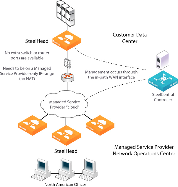
Management In-Path interface deployment
MIP interface dependencies
A MIP interface has these dependencies:
•IPv6 addresses are supported for MIP interfaces starting with RiOS version 9.5.
•Any connections destined to a MIP interface aren’t optimized by that SteelHead and don’t appear in the Current Connections report.
•A MIP interface can’t reside in the same subnet as the primary or auxiliary interfaces. It can’t share the same subnet with any other interfaces on the SteelHead.
•A MIP interface must be in its own subnet.
•You can’t enable a MIP interface after fail-to-block has been enabled and the corresponding in-path interface fails. When fail-to-block is enabled, in the event of a failure or loss of power, the SteelHead LAN and WAN interfaces completely lose link status. The failed SteelHead blocks traffic along its path, forcing traffic to be rerouted onto other paths (where the remaining SteelHeads are deployed). For details on fail-to-block, see the SteelHead Deployment Guide.
•You can’t reach a MIP interface when Link State Propagation (LSP) is also enabled and the corresponding in-path interface fails. In physical in-path deployments, LSP shortens the recovery time of a link failure. LSP communicates link status between the devices connected to the SteelHead and is enabled by default. To disable LSP, enter the no in-path lsp enable CLI command at the system prompt.
•This feature supports 802.1Q VLAN.
•A MIP interface uses the main routing table.
Enabling a Management In-Path interface
Use the controls in this page when you need to enable a MIP interface or the interface requires additional configuration.
To enable a management in-path interface
1. Choose Networking > Networking: In-Path Interfaces to display the In-Path Interfaces page.
2. In the In-Path Interface Settings pane, click the arrow next to the name of an in-path interface to expand it and scroll down to the Mgmt Interface pane.
3. In the Mgmt Interface pane, complete the configuration as described in this table.
Control | Description |
Enable Appliance Management on This Interface | Enables a secondary MIP interface that you can reach through the physical in-path LAN and WAN interfaces. Configuring a secondary MIP interface allows management of SteelHeads from a private network while maintaining a logical separation of network traffic. Note: If LSP or fail-to-block is enabled, a message reminds you to disable the feature before enabling the MIP interface. |
IPv4 Address | Specify the IPv4 address for the MIP interface. |
IPv4 Subnet Mask | Specify the IPv4 subnet mask. |
Enable IPv6 | Select this check box to assign an IPv6 address. IPv6 addresses are disabled by default. You can only assign one IPv6 address per in-path interface. |
IPv6 Address | Specify the IPv6 address for the MIP interface. |
IPv6 Prefix | Specify the IPv6 prefix. The prefix length is 0 to 128 bits, separated from the address by a forward slash (/). In the following example, 60 is the prefix: 2001:38dc:52::e9a4:c5:6282/60 |
VLAN Tag ID | Specifies a numeric VLAN Tag ID. When you specify the VLAN Tag ID for the MIP interface, all packets originating from the SteelHead from the MIP interface are tagged with that identification number. The VLAN Tag ID might be the same value or a different value than the in-path interface VLAN tag ID. The MIP interface could be untagged and the in-path interface could be tagged and vice versa. A zero (0) value specifies nontagged (or native VLAN) and is the correct setting if there are no VLANs present. For example, if the MIP interface is 192.168.1.1 in VLAN 200, you would specify tag 200. |
4. Click Apply to apply your changes to the running configuration.
5. Click Save to Disk to save your settings permanently.
After you apply your settings, choose Reports > Networking: Interface Counters to view MIP interface statistics.
You can remove MIP interfaces from the main routing table in the Networking > Networking: Base Interfaces page.
Related topics