End-to-End Topology
This topic presents a detailed, complete topology. It describes the following scenarios:
Full topology
In this topic, we step through elements of this network, which is representative of many Riverbed SD-WAN customers. All the scenarios in this chapter are derived from this topology.
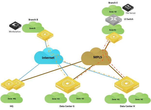
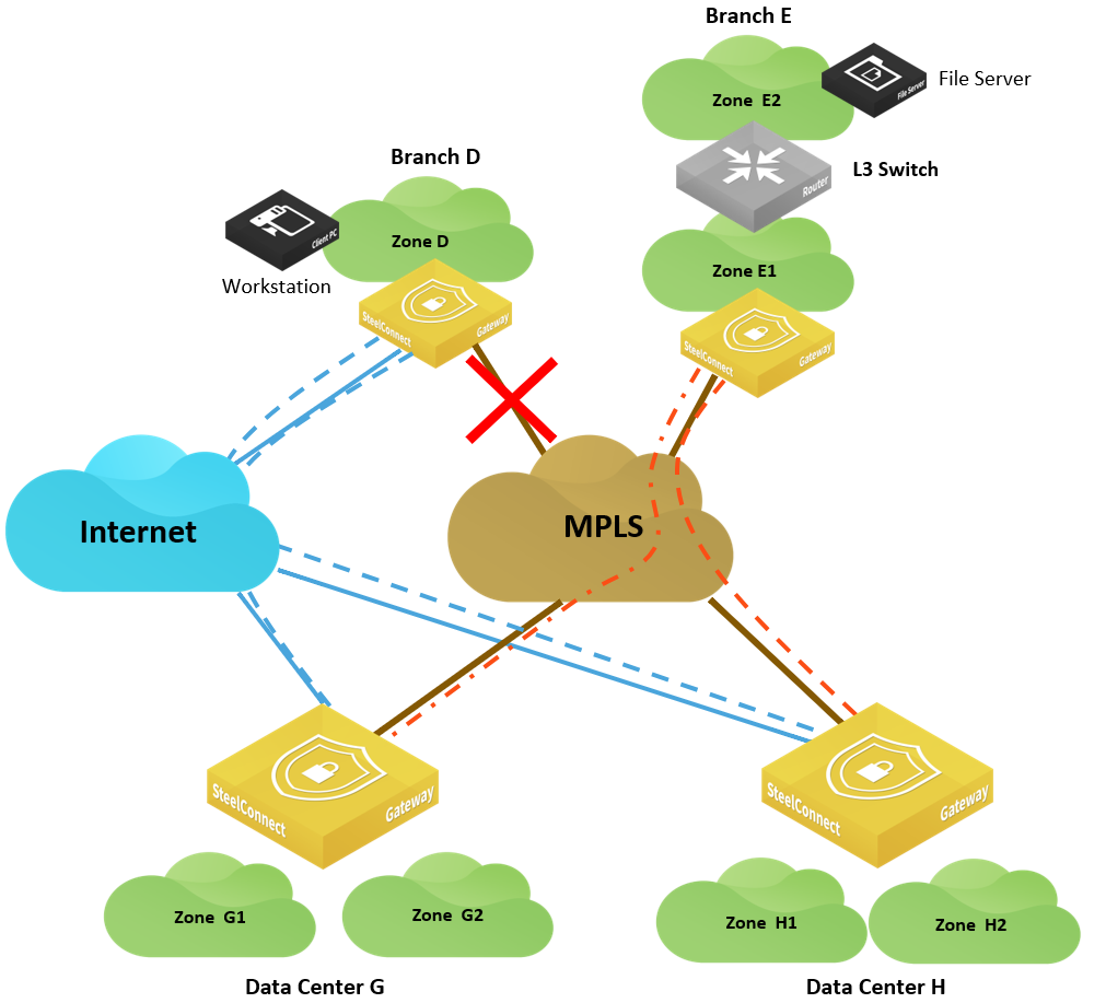
Full sample network

The network paths shown in
Full sample network use these conventions:
•Gray dotted lines represent a classic VPN in SCM.
•Blue dotted lines represent a RouteVPN tunnel.
•Orange dotted lines represent the AutoVPN in full-mesh connectivity.
•Yellow dotted lines represent RouteVPN connections in hub-and-spoke mode.
The topology has these components:
•Branch A is a legacy site connected to HQ (headquarters) through an IPsec tunnel from its firewall.
•Branch B is an SD-WAN site with only internet connectivity. It is configured as a leaf with two hubs, Data Center G and Data Center H.
•Branch C is an SD-WAN site with only internet connectivity. As opposed to Branch B, Branch C participates in a full-mesh overlay on the internet.
•Branch D is an SD-WAN site with MPLS and internet connectivity.
•Branch E is an SD-WAN site connected through MPLS only.
•Branch F is a legacy site with a third-party router connected to MPLS only.
•HQ is the headquarters connected through the internet and MPLS and is equipped with a pair of SDI-1030 appliances in a high-availability configuration.
•Data Center G and Data Center H are connected to MPLS and internet. The data centers are equipped with SDI-5030 appliances.
The diagram is not suggesting a possible in-path deployment of SDI-5030 appliances. For clarity and simplification of the topology in the data centers, internet firewalls, aggregation routers, and BGP neighbor adjacencies are not depicted. Furthermore, SDI-5030 can be deployed as a single-unit cluster or n+k-units cluster. To get more details on SDI-5030 implementation, see
Data Center Topologies. The following sections detail the different use cases and configurations to implement this network and explain the different brownfield scenarios, meaning how an SD-WAN site can communicate with a non-SD-WAN site. The brownfield scenarios are extremely important to consider during an SD-WAN project, especially during the transformation phase.
Connecting sites with the same WAN
The topics in this section show how sites using the same WAN can connect.
SD-WAN sites communicating between each other
By default, SD-WAN sites operate in a full-mesh mode on the internet. Tunnels are formed automatically and they learn the subnets of each other through the overlay network.
On a private network, such as MPLS, it is possible to use the underlay directly; however, we recommend you enable encryption when defining the WAN MPLS to benefit from all SD-WAN capabilities (including quality-based path selection). When encryption is on, SD-WAN appliances form the overlay tunnels automatically. For more details, see
Integration with private networks.
Brownfield scenario: SD-WAN site communicating with legacy internet site
In this scenario, a workstation in Branch A wants to connect to a server hosted in Branch C. Branch A is equipped with a third-party firewall. An IPsec tunnel is configured between the firewall and the SDI-1030 appliances at the headquarters (HQ) office.
You could create another IPsec tunnel between the firewall in Branch A and the gateway in Branch C. However, depending on the number of sites, it might be difficult to maintain and scale this deployment.
Let’s consider how to transit traffic through the HQ classic VPN tunnel from our branch sites. This requires minor modifications on the third-party device and minimal configuration in SCM.
SD-WAN site with legacy branch
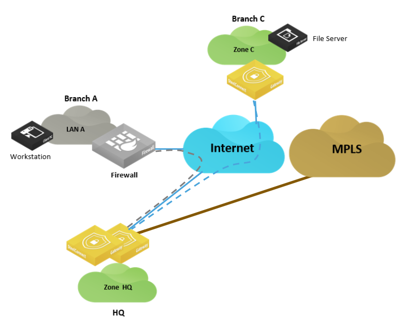
In this situation, the traffic between Zone C and Zone A travels through the RouteVPN. The HQ gateway routes traffic based on longest prefix match over the classic VPN to Zone A, a LAN segment in Branch A.
To configure this brownfield scenario
1. Create a classic VPN between the HQ gateway and the firewall at Branch A.
Choose Network Design > ClassicVPN and click New ClassicVPN connection.
2. Define traffic path rules for traffic from the branch to traverse the RouteVPN.
Choose Rules > Traffic Rules and click New Traffic Rule.
3. Add an outbound rule allowing traffic from Zone C to the classic VPN.
–Choose Rules > Outbound / Internal and click New policy rule.
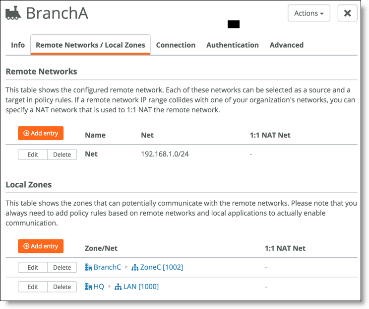
–The remote network definition is the subnets behind the Branch A firewall.
–The local zones define Branch C, Zone C, and HQ LAN 1000. This creates a proxy ACL defining what traffic needs to be encrypted between HQ and Branch A. This configuration must be a mirror image of the configuration on the firewall.
4. Choose Network Design > ClassicVPN and add a new classic VPN connection.
5. Modify the remote networks to reflect the local and remote networks to be encrypted.
Remote and local networks
Here is an example of the firewall configuration (in VyOS):
tunnel 0 {
allow-nat-networks disable
allow-public-networks disable
esp-group office-srv-esp
local {
prefix 192.168.1.0/24
}
remote {
prefix 172.16.0.0/24
}
}
tunnel 1 {
allow-nat-networks disable
allow-public-networks disable
esp-group office-srv-esp
local {
prefix 192.168.1.0/24
}
remote {
prefix 172.16.4.0/24
}
}
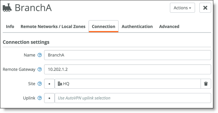
Connection settings define the remote gateway (Branch A firewall) and HQ as the tunnel endpoints.
6. Confirm the connection terminates at HQ.
If you select the branch site instead of the HQ site, the tunnel fails to establish.
Connection settings
7. In the Advanced tab, match the VPN parameters between the firewall and the Branch A configuration.
Advanced settings
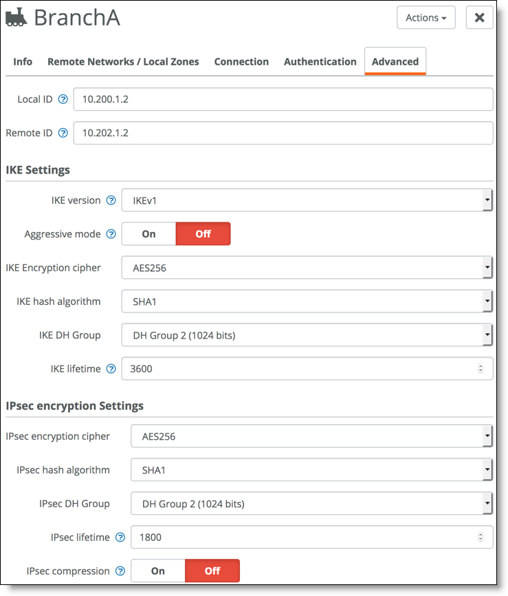
It is important that the IKE settings and the IPsec settings match. Here is an example configuration from the firewall (VyOS):
ipsec {
esp-group rvbd-esp { <----- Matches the IPsec settings in the classic VPN configuration.
lifetime 1800
proposal 1 {
encryption aes256
hash sha1
}
}
ike-group rvbd-ike { <----- Matches the IKE settings in the classic VPN configuration.
lifetime 3600
proposal 1 {
encryption aes256
hash sha1
}
}
ipsec-interfaces {
interface eth0
}
Additionally, the local and remote ID is overridden in the classic VPN configuration so that FQDN is not used to establish the tunnel.
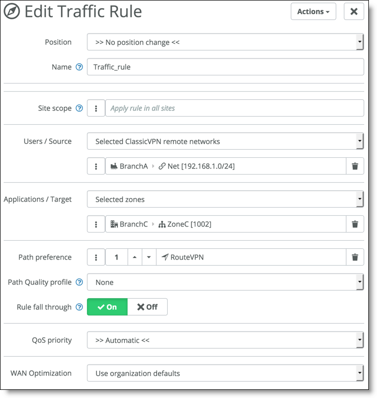
8. Choose Rules > Traffic Rules and create a traffic rule to send traffic between the branches over RouteVPN.
Creating a traffic rule
9. To get Branch C to forward traffic to Branch A, a route must be learned on the Branch C gateway. To accomplish this, add a zone to HQ advertising a supernet of the subnet at Branch A.
10. Choose Network Design > Zones and add a zone to advertise the prefix of the branch sites.
Zone
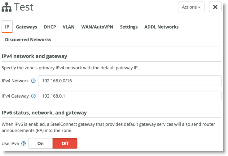
to advertise the prefix of the branch sites
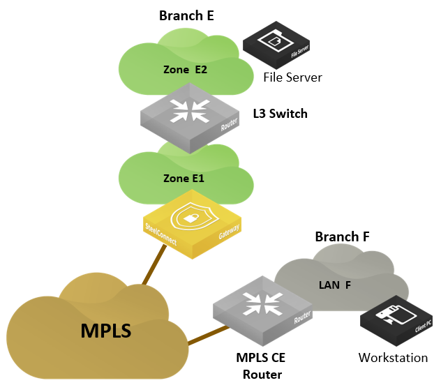
Brownfield scenario: SD-WAN site communicating with legacy MPLS site
In this scenario, a workstation in Branch F requests files on the server hosted in Branch E.
Legacy MPLS site
The Riverbed SD-WAN solution can send and receive traffic with the underlay network. As long as the SD-WAN gateway is configured to advertise its local subnets on MPLS and can learn routes from the MPLS network, it can communicate through the underlay. For more information, see
Integration with MPLS CE router and
MPLS CE router replacement: ASBR-like deployment.
Connecting sites with different WANs
The topics in this section show how sites using different WANs can connect.
SD-WAN sites: multihub
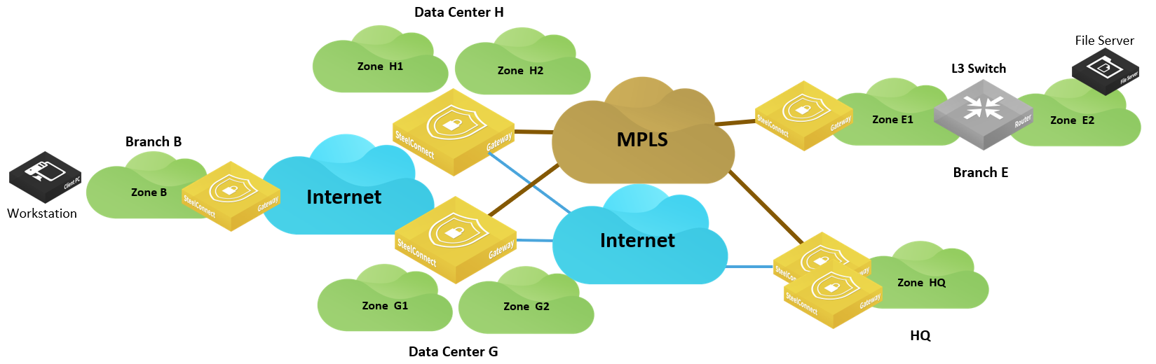
In this scenario, a workstation in Branch B wants to connect to a server hosted in Branch E. Both sites are in different WANs: Branch B connected to the internet and Branch E connected only to MPLS.
Connecting WANs of different types
This deployment requires a transit site that interconnects both WANs. In this example, it could be either the HQ (headquarters) or either of the data centers.
For this example, we’ll configure Branch B as a leaf in a hub-and-spoke topology, Data Center G as the primary hub, and Data Center H as the secondary.
The following figure rearranges the topology for better visualization.
Visualizing the transit site deployment
To configure this scenario supporting different WANs
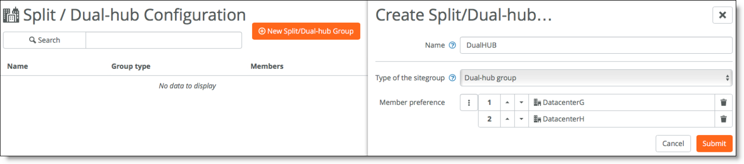
1. Create a dual-hub configuration and assign it to the site.
In SCM, choose Network Design > Split site/Dual-hub and click New Split/Dual-hub Group. For this example, select Dual-hub group as the type of site group and select DatacenterG and DatacenterH as members of the group.
Dual-hub configuration
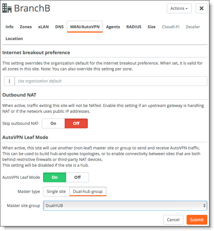
2. Assign the dual-hub configuration to a site.
Choose Network Design > Sites, select Branch B and select the WAN/AutoVPN tab. Configure Branch B as a leaf, select dual-hub group as the master type, and select the group created in the previous step.
Configuring Branch B in AutoVPN leaf mode
With this configuration, Branch B can access the resources in Branch E (and vice versa) but also access resources in HQ through Data Center G and alternatively through Data Center H. Traffic is steered on the overlay network.
In this example, Data Center G and Data Center H are equipped with SDI-5030 appliances. Other models can be deployed as dual-hub. The following SteelConnect gateways support this topology.
SDI-VGW | SDI-130/130W | SDI-330 | SDI-1030 | SDI-5030 |
| | | | |
SD-WAN sites: full-mesh mode
This scenario is similar to the previous one, except Branch C is in full-mesh mode over the internet. By default, the gateway in Branch C has no knowledge of Branch E subnets.
Different WANs with full mesh

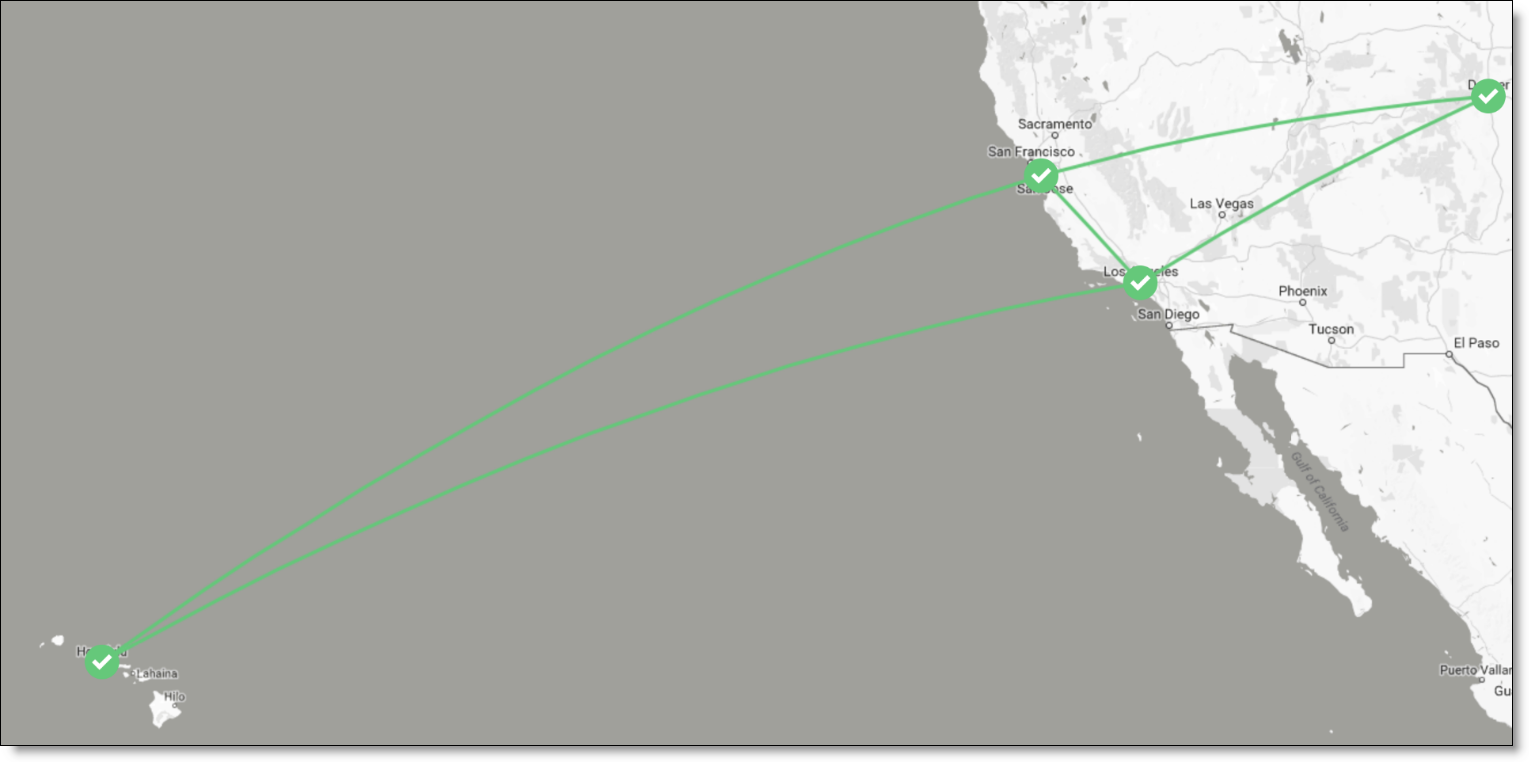
For this scenario, assume that Branch C is already connected to both data centers over the internet. Branch E is also connected to the data centers over MPLS. (Branch C is in Honolulu, Branch E is in Denver, Data Center G is in Los Angeles, and Data Center H is in Sunnyvale.)
Branch C and Branch E connected to data centers
To configure this scenario
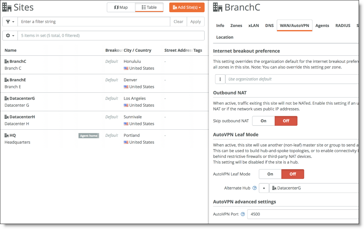
1. Configure Data Center G as an alternate hub for Branch C.
Choose Network Design > Sites and select Branch C. Under the WAN/AutoVPN tab, add DatacenterG as an alternate hub.
Adding an alternate hub
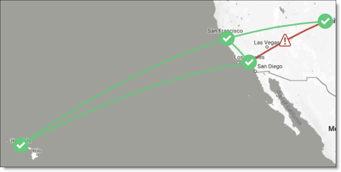
At this stage of the configuration, the workstation in Branch C can access the server in Branch E (and vice versa). If the internet or MPLS connection in Data Center G goes down, the branch sites C and E are no longer able to connect.
Connection down between Branch C and Branch E
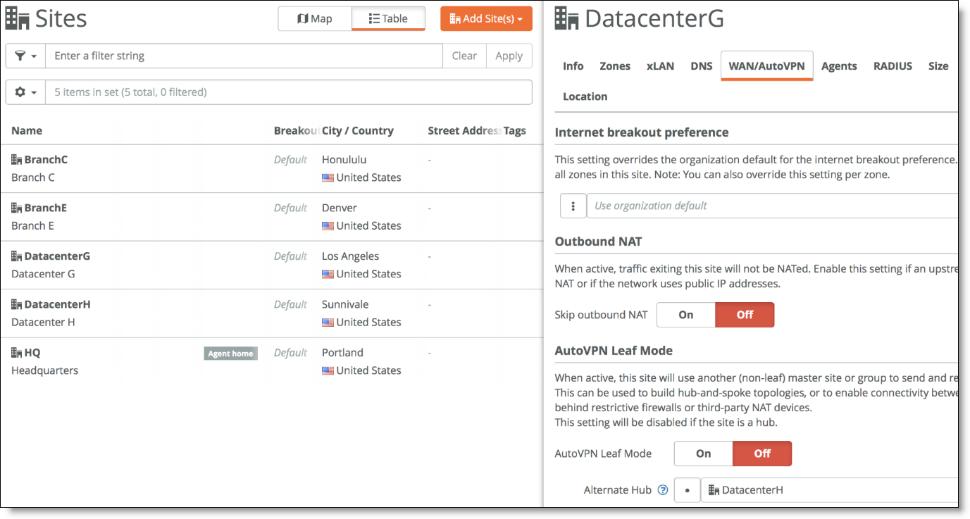
To provide more resiliency, configure Data Center H as the alternate hub for Data Center G so if MPLS goes down, Data Center G knows that it can send traffic destined to the MPLS network through Data Center H.
Configuring Data Center H as the alternate hub
In version 2.10, you can configure only one alternate hub for a site. If Data Center G goes down, Branch C won’t be able to communicate with Branch E anymore. This will be enhanced in a future release.
In this example, Data Center G and Data Center H are equipped with SDI-5030 appliances. Other models can be deployed as alternate hub. The following SteelConnect gateways support this topology.
SDI-VGW | SDI-130/130W | SDI-330 | SDI-1030 | SDI-5030 |
| | | | |
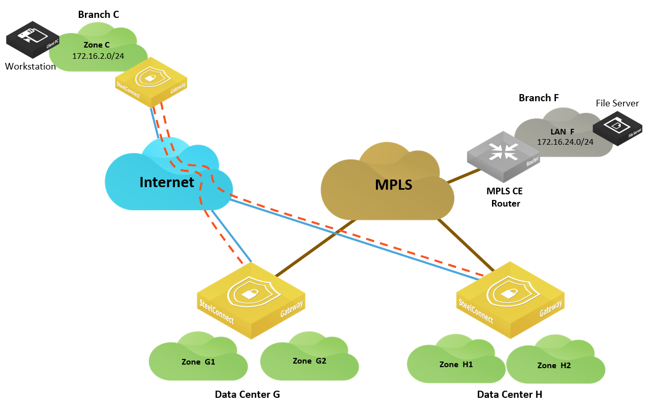
Brownfield scenario: SD-WAN site communicating with legacy site
In this scenario, a user in Branch C needs to access files on a server hosted in Branch F. Branch F is not equipped with Riverbed SD-WAN technology. It has a traditional CE router providing connectivity to the MPLS network.
In this case, it is not possible to leverage the power of an overlay network exclusively. You have to rely on the underlay and its routing protocols.
SD-WAN and legacy site
On SteelConnect version 2.10, SDI-5030 appliances cannot discover routes locally through BGP. They can only announce locally the subnets (zones) that are configured on SteelConnect Manager to attract the traffic destined to them.
Tip: An enhancement is scheduled for the next version (2.11) that will gracefully handle that scenario.
In version 2.10, you can use a workaround to attract the traffic in the data centers so they transit traffic between the two WANs. For that to happen, create a supernet in Data Center G that will be announced in the overlay for Branch C to send the traffic to Data Center G. The supernet will be advertised through BPG on the MPLS so Branch F sends the traffic the Data Center G.
To ensure redundancy and make sure that if Data Center G is down, Branch C and Branch F are able to communicate between each other, configure both data centers as split data centers. Configure the supernet zone in both data centers.
To configure this topology
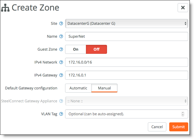
1. Create a supernet zone in Data Center G.
Choose Network Design > Zones and click New Zone.
Creating a zone in Data Center G
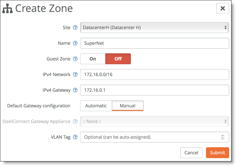
2. Create the same zone in Data Center H.
Creating a zone in Data Center H
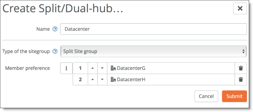
3. Choose Network Design > Split site/Dual Hub and create a new Split Site group with both data centers.
Creating a split site group for both data centers
In this example, Data Center G and Data Center H are equipped with SDI-5030 appliances. The split data center use case only supports the SDI-5030 appliances.
SDI-VGW | SDI-130/130W | SDI-330 | SDI-1030 | SDI-5030 |
| | | | |
SD-WAN sites: path redundancy
In this scenario, the MPLS connection in Branch D goes down and you want to guarantee business continuity for a workstation in Branch D that needs to retrieve files from a server hosted in Branch E.
Path redundancy for SD-WAN sites
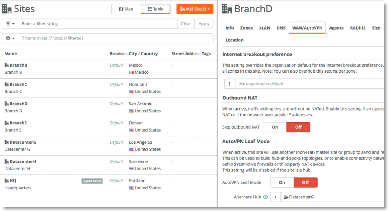
In this case, configure Branch D to use data center G as an alternate hub.
Choose Network Design > Sites, select Branch D and in the WAN/AutoVPN tab specify DatacenterG as the alternate hub.
Configuring as an alternate hub
In this example, Data Center G and Data Center H are equipped with SDI-5030 appliances. Other models can be deployed as alternate hub. The following SteelConnect gateways support this topology.
SDI-VGW | SDI-130/130W | SDI-330 | SDI-1030 | SDI-5030 |
| | | | |
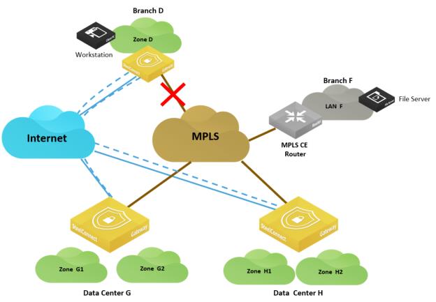
Brownfield scenario: path redundancy
In this scenario, the MPLS connection in Branch D goes down and you want to guarantee business continuity for a workstation in Branch D that needs to retrieve files from a server hosted in Branch F.
Path redundancy for mixed sites
This is the same situation as the
Brownfield scenario: SD-WAN site communicating with legacy MPLS site and you can apply the same configuration.