Data Center Topologies
This topic describes advanced topologies that we have qualified for enterprise data centers. It includes these sections:
Using HA LAN and WAN topologies in the data center
You can leverage the high-availability LAN topologies and WAN topologies presented in the
LAN Topologies and
WAN Topologies topics for designing data center architectures with SteelConnect gateway appliances.
High availability in the data center is an example of a deployment that can be achieved using the configurations described in the LAN and WAN topology chapters.
High availability in the data center

We recommend you use only SDI-VGW and SDI-1030 in the branch for HA data center deployment.
Traffic attraction with SDI-5030
In contrast to branch gateways that handle in-path traffic, the 5030 data center gateways are deployed out of path deep inside the data center network. Because the 5030 gateways are placed physically out of path from the data flow, you can deploy them with no network downtime. The system relies on traffic redirection.
Traffic attraction means that the 5030s exchange routes through eBGP with the aggregation routers. All traffic that reaches these routers destined to the branch is directed to the 5030s, is IPsec encapsulated with our AutoVPN mechanisms, and is sent in the overlay tunnel to the branch.
All ports that have internet connectivity (including the management port) need to be protected by your security infrastructure.
Data center and branch end-to-end architecture

At a high level, you need to complete these tasks to configure this topology:
Cabling the appliances
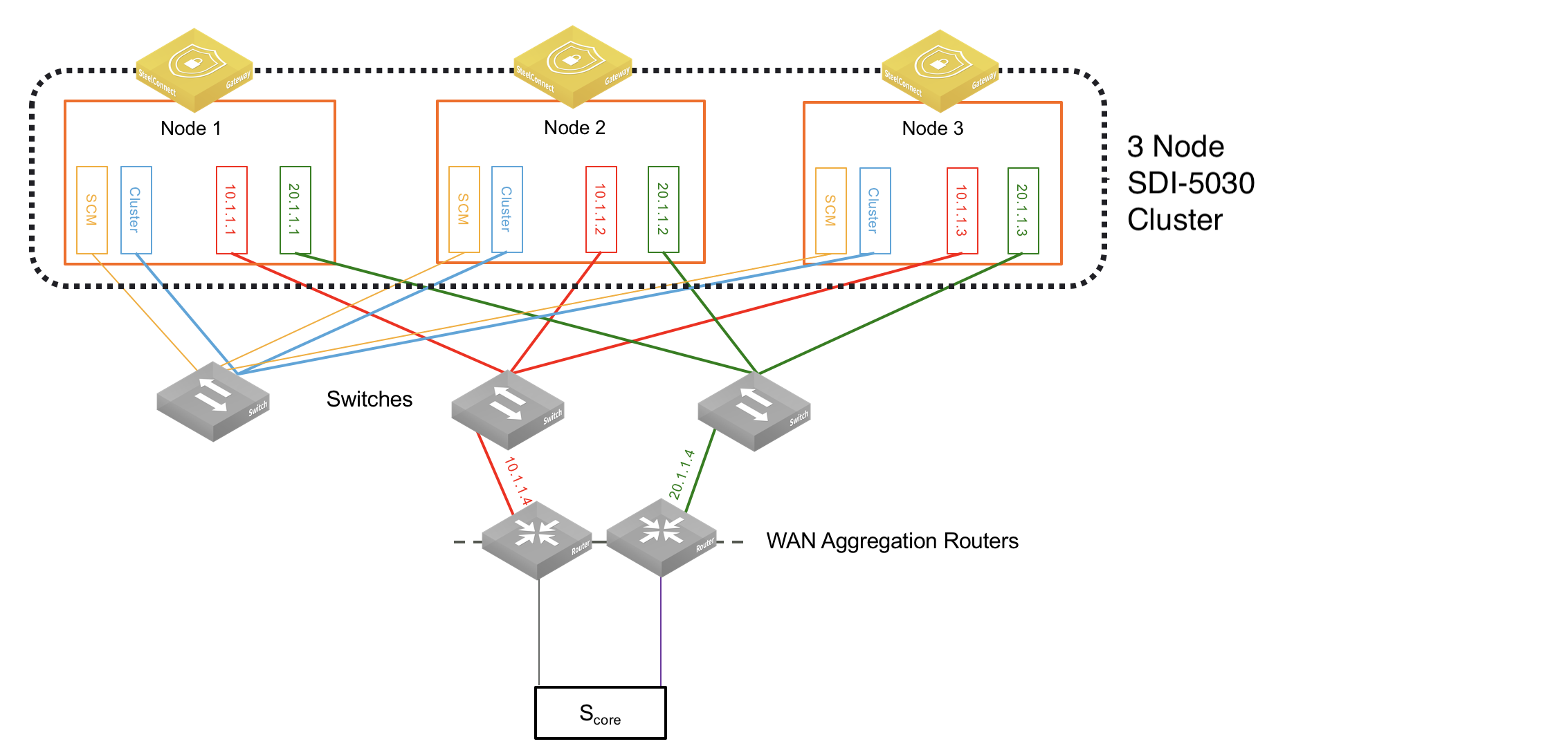
The first step when setting up a data center deployment is to connect the SDI-5030 appliances to the network. Because the 5030 gateways are placed physically out of path from the data flow, you can deploy them with no network downtime. For a cluster, we recommend identically cabling the gateways for redundancy.
5030 gateways use ports 1 and 2 for system-related tasks. The remaining ports are data ports.
•Port 1 is the management port dedicated to SCM. It is required to use DHCP to allocate dynamically the management IP address. This network must provide connectivity to the internet to allow calls to the SteelConnect Manager. DNS support is mandatory to access Riverbed services. The management port should not be accessible directly from the public internet. This port should be behind your firewall/security complex and it only requires enabling the documented outbound services.
•Port 2 is a dedicated cluster connectivity port, providing an internal, private physical connection between the 5030 gateways for cluster synchronization and high availability. All 5030 gateways must be Layer 2 adjacent in this network.
•Ports 3 through 10 are data ports for LAN and WAN traffic.
•Ports 5 and 6 can provide both 10G and 1G connectivity.
Whenever possible, we recommend using 10G capable ports (even for 1G connections) to guarantee best performance.
In the following example, there are two WAN connections (shown in this figure in red and green).
Three node 5030 cluster
Registering the appliances to the organization
Next, register the appliance.
To register the appliance
1. In SCM, choose Appliances > Overview.
2. Click Add appliances and choose Register Hardware Appliance from the drop-down menu.
3. Provide the serial number and click Submit.
Registering the appliance
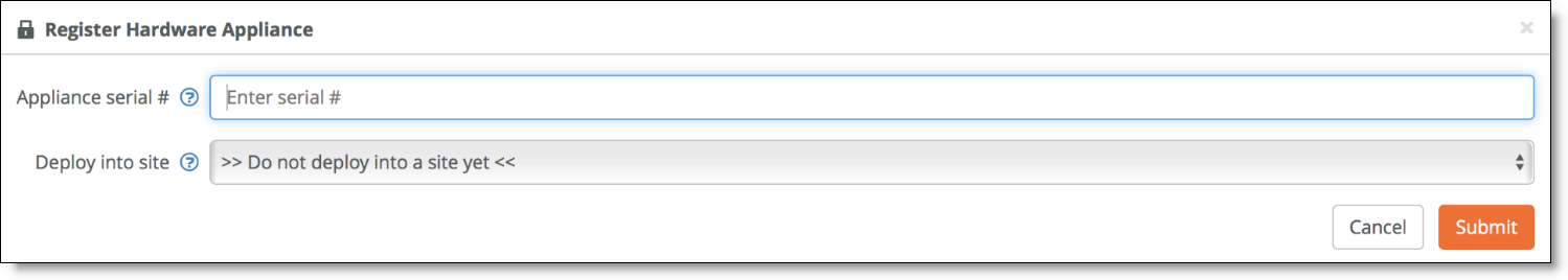
Don't assign the appliance to a site yet; you complete this step later in the process.
When the appliance is registered, it downloads the latest firmware and starts the installation. We highly recommend completing the upgrade process before moving to the next steps.
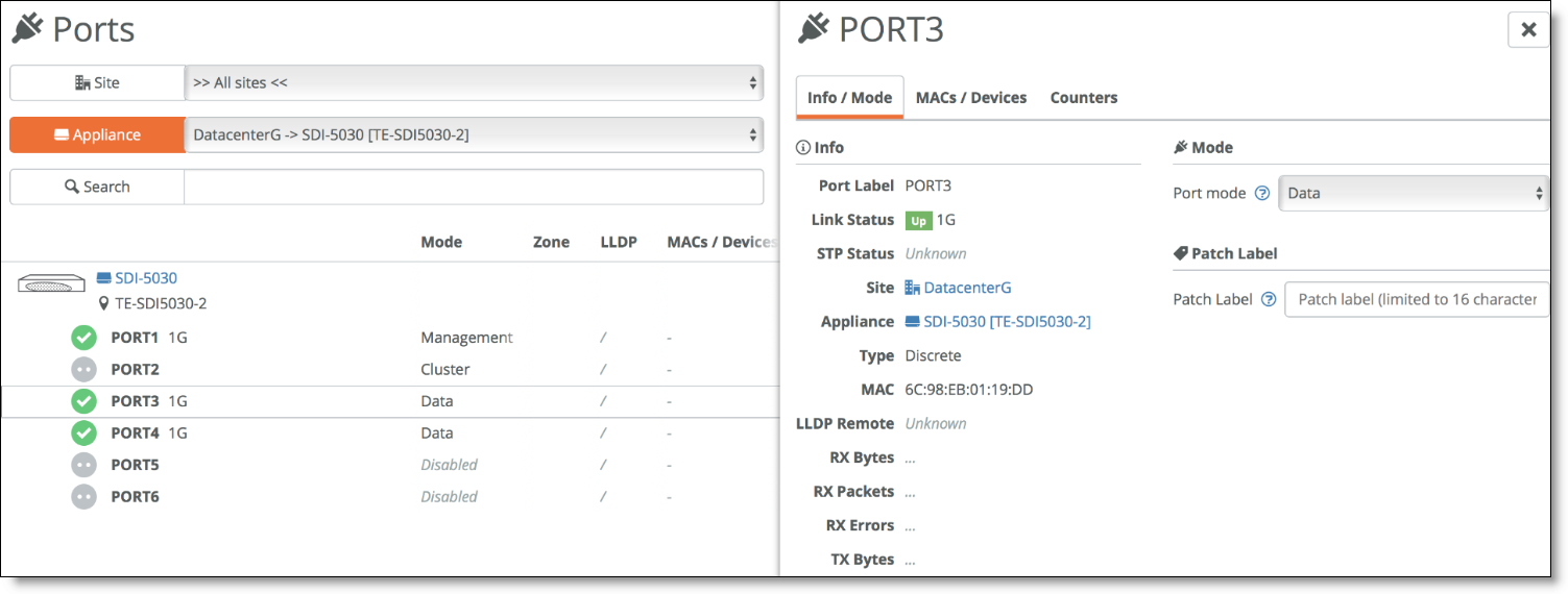
Enabling the data ports
Each 5030 appliance must have at least one data port connected to the WAN.
To enable data ports to use for the 5030 WAN connections
1. Choose Appliances > Ports.
2. Click the 5030 ports to use as a data port.
3. In the Info/Mode tab, set the port mode to Data.
Enabling data ports
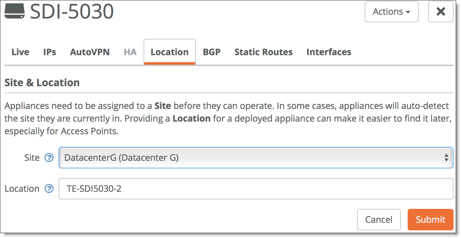
Deploying the appliances in a site
At this stage of the process, you can assign the appliances to the sites.
To deploy an appliance to a site
1. Choosing Appliances > Overview.
2. Click the appliances to configure and go to the Location tab.
3. Specify the site and a location and click Submit.
Assigning the site and location
Creating a data center cluster of 5030 gateways
To accommodate data center workloads, 5030 gateways are designed to operate in a cluster. Clusters provide resiliency and reliability in addition to higher bandwidth throughput. A cluster requires a minimum of three 5030 gateways to provide high availability with two gateways as active nodes and one as a spare node.
You can have a single 5030 in your data center deployment but you miss the advantages of a cluster and high availability.
To create a new data center cluster of 5030 gateways
1. Choose Network Design > Clusters. Click New Cluster.
2. Specify a cluster name. Select the site to deploy the cluster from the drop-down list. In this example, deploy it at DataCenterG.
Tip: In a cluster workflow, it can be difficult to differentiate between data center gateways in a cluster when they are referenced on various SCM pages. We strongly recommend that you always specify a detailed location for the gateway using the Location field under the Location tab in the appliance page. Setting the location associates a gateway with its location wherever an appliance is referenced, making it easy to identify.
Creating a cluster

3. Select the cluster members from the drop-down list.
4. Specify the number of failover nodes. By default, the system creates one failover node in a cluster of three 5030 gateways. For a single 5030 cluster, leave the number of failover nodes at 0.
5. For Interceptor, select Off to enable traffic attraction.
Traffic attraction means that the 5030s will exchange routes via eBGP with the aggregation routers so that all traffic that reaches these routers destined to the branch is directed to the 5030s, is IPsec encapsulated, and is sent in the overlay tunnel to the branch.
6. Click Submit.
Using BGP for traffic attraction on SCM
The SDI-5030 is not an in-path device and needs BGP to peer with a WAN aggregation stack within a data center. This is required not only for route attraction to occur but also to ensure proper cluster function by prepending BGP advertisements. BGP is critical to ensure the internal and cluster load-balancing.
Use BGP traffic attraction to attract traffic bound for the branches to the data center gateways and to perform traffic tunneling and redirection.
One or more SDI-5030 gateways that are deployed as a data center gateway cluster peer with a WAN distribution router using BGP.
The cluster of SDI-5030 forms an eBGP peering relationship with the WAN distribution routers.
The cluster then advertises Local Tunnel Endpoint (LTEP) subnets as well as the remote subnet prefixes (of the SD-WAN equipped sites) for traffic attraction into the SD-WAN (overlay) network.
In the opposite direction, the data center’s aggregation routers communicate to the 5030 gateways all the prefixes they need to route to data center subnets, including branch Tunnel Endpoint (TEP) addresses and the branch subnets for all non-SD-WAN branches.
To configure the individual 5030 gateways with local BGP information
1. Choose Appliances > Overview.
2. Select an appliance.
3. Select the Interfaces tab and configure the IP address for each data port.
Interfaces tab

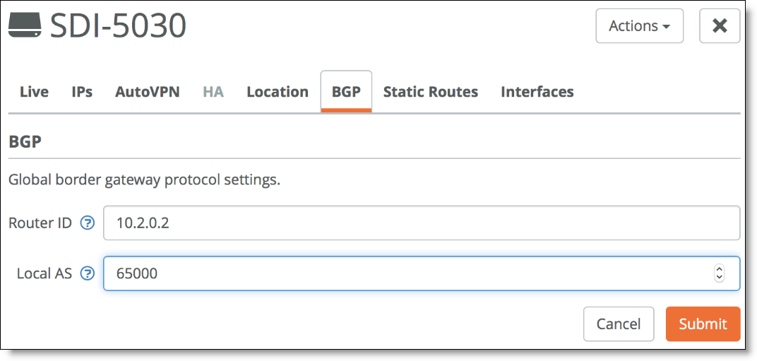
4. Select the BGP tab.
5. Add the unique Router ID for this appliance and the Local AS.
For each SDI-5030 appliance, you need to allocate a unique BGP AS number. Router ID is the IP address of the Data Interface 3.
Configuring local BGP information
6. Repeat these steps for all 5030 gateways in the cluster.
Next, configure the BGP information for the cluster. The cluster needs the router information to communicate with the 5030 gateway.
To configure BGP information for a data center cluster
1. Choose Network Design > Cluster.
2. Select the cluster.
3. Select the BGP tab.
4. Click Add BGP Neighbor.
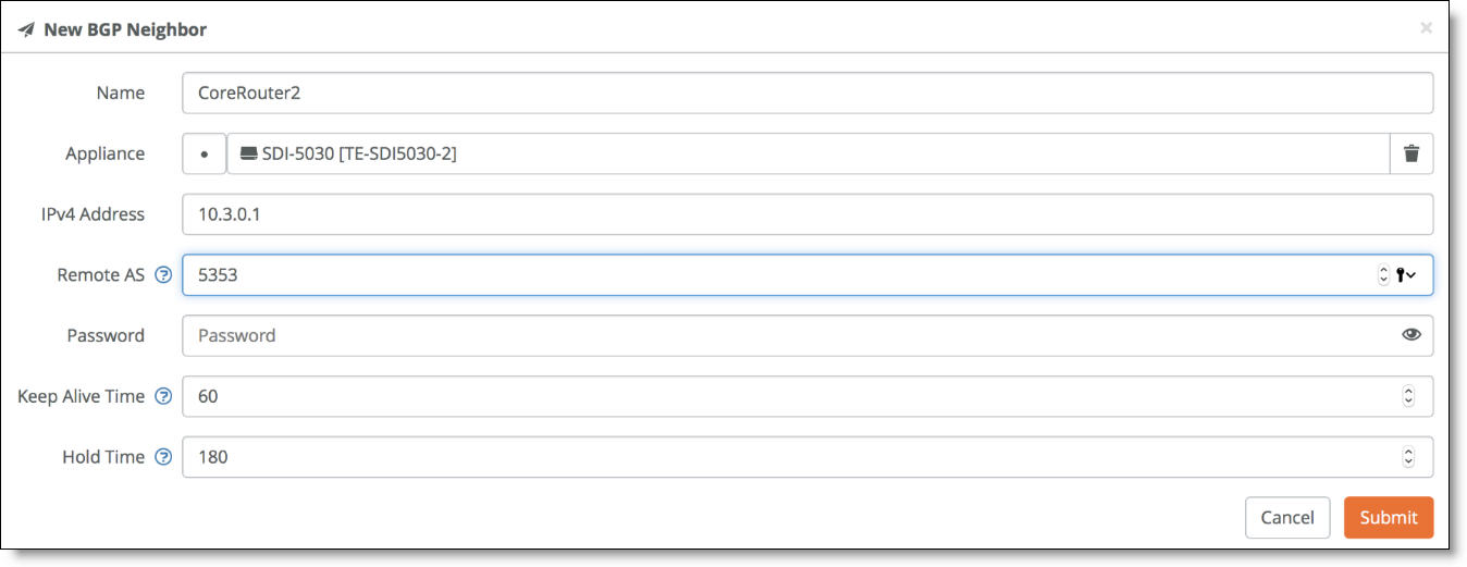
5. Specify a name for the neighbor.
6. Specify the IPv4 address of the neighbor.
7. Specify the Remote AS number the neighbor belongs to. In this example, 5353.
8. In the Password field, type a password to enable MD5 authentication. You must use the same password on both BGP neighbors. This field is optional if you don’t require MD5 authentication.
9. Enter the Keep Alive Time and Hold Time in your network. The defaults are 60 and 180, respectively. Use these values if they are acceptable for your environment.
10. Click Submit.
Configuring BGP information for a data center cluster
11. Repeat Steps 3 through 10 to create additional neighbors. Because there are three 5030 gateways and two WAN connections for each, there are a total of six BGP neighbors to add.
The SDI-5030 does not yet support LAN-side route retraction and/or dynamic LAN-side zone learning. At this time, the SDI-5030 does not withdraw a route to a remote zone. Once a network is configured in SCM, it is advertised by the SDI-5030 via BGP regardless of the tunnel state to the remote site. The SDI-5030 does not learn routes in the data center.
Configuring BGP on the WAN aggregation routers
The data center aggregation routers must communicate with the 5030 gateways about the data center subnets reachability. Also, these routers need to establish a BGP neighbor relationship with the 5030 gateways so that routes are exchanged and packets destined to the branches are first sent to the 5030 gateway for encapsulation.
With 5030 gateways, you need central VPN keying (C-VPN-K).
In this topology, there are two WAN aggregation routers used for redundancy. Both routers must be configured for the BGP session using the command-line interface as follows:
router bgp 5353
bgp log-neighbor-changes
network 192.168.25.0
network 192.168.26.0
network 192.168.27.0
network 172.16.3.0
neighbor 192.168.25.1 remote-as 65000
neighbor 192.168.25.2 remote-as 65002
neighbor 192.168.25.3 remote-as 65004
no auto-summary
See your WAN router aggregation vendor documentation for more detailed configuration information.
Creating data center uplinks for the cluster
Next, configure the data center uplinks. On a 5030 gateway, a data port physically connects the cluster to the network. Uplinks on a 5030 gateway are logical. A cluster must have at least a single uplink or multiple uplinks to the same WAN and can connect to multiple WANs. This topology has three WANs, so you need to configure two WANs, so you need to configure two data center uplinks: one for the internet WAN and one for the MPLS WAN.
To create data center uplinks for the cluster
1. Choose Network Design > Clusters.
2. Select a cluster to associate with the uplink. Each uplink is cluster specific and its connection type differs between clusters.
3. Select the Datacenter Uplinks tab. Click Add Datacenter Uplink.
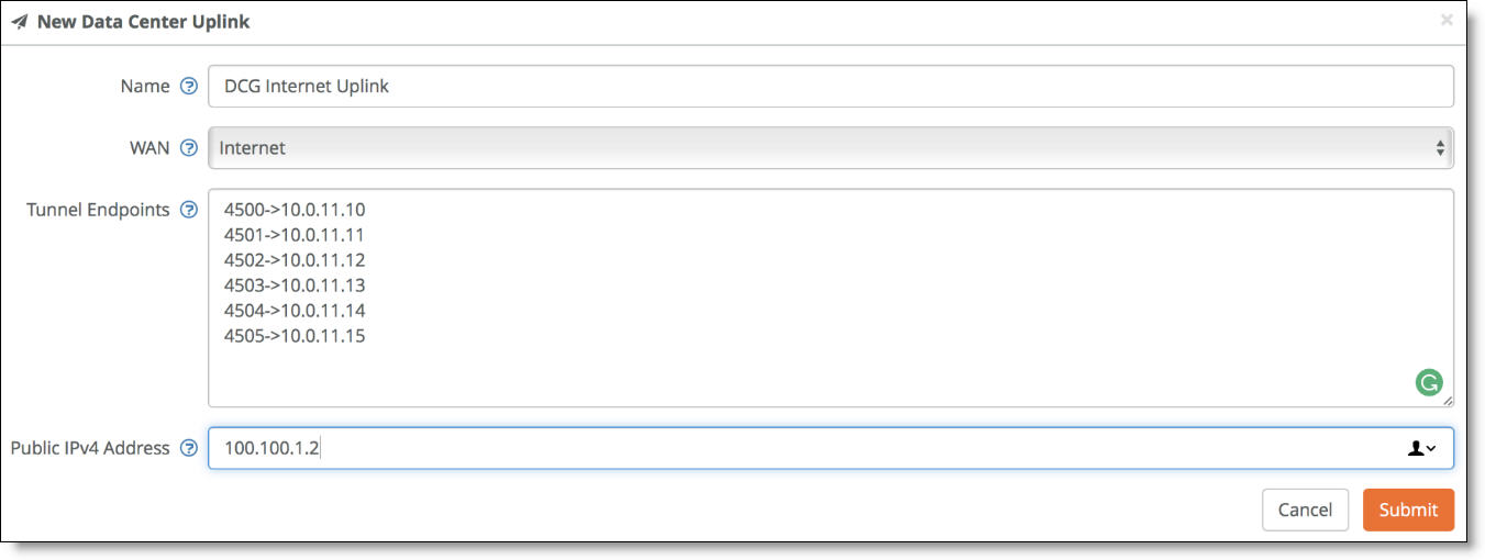
4. Type the uplink name.
5. Select a WAN.
6. Under Tunnel Endpoints, enter the IP addresses of the tunnel endpoints.
For each appliance, two TEP IP addresses are required per WAN.
A UDP port is required only for the internet WAN and must be allocated. Any internet firewall needs to forward these ports to the TEP IP address.
These IP addresses can be any addresses as long as they are unique in the network. They can be considered as loopback IP addresses.
For three appliances in the cluster, add two tunnel endpoints for each gateway, resulting in six endpoint IP addresses for internet.
7. Specify the public IPv4 address of the uplink with an optional netmask. This address is required for internet WANs and optional for other WANs. In this example topology, the address is 100.100.1.2.
8. Click Submit.
Data center uplink for the internet WAN
9. Repeat these steps for the MPLS WAN.
Data center uplink for the MPLS WAN

NAT ports for the tunnel endpoints are only required for the internet WAN. Because the MPLS WAN is a private circuit, no public IPv4 address is needed.