Installing Network Interface Cards
You can install add-on or replacement network interface cards (NICs) in both 1U and 2U appliances. However, installation procedures vary by appliance model, as NIC slot sizes, layouts, and positions differ between models. Use the information in this chapter to identify your appliance model and correctly install your NICs.
Before installing NICs, ensure your appliance has the required software:
• All SteelHead Interceptor NICs require 8.0.0 software or later. 100G NICs require 8.1.1 software or later.
• Most SteelHead NICs require 9.9.0 software or later. The QuickAssist Technology (QAT) Compression/Acceleration card requires 9.9.2 software or later. The Four-Port 10-GbE Copper NIC and Four-Port 10-GbE DAC require 9.10.0 software or later.
For details about supported NICs, including part numbers, see
Reference: Supported NICs and Slot Configurations.For details about supported NIC configurations and slot restrictions, see Reference: Supported Slot Configurations.
Before configuring NICs, consider whether you want the NICs to fail-to-wire or fail-to-block. For details, see
About fail-to modes.About NIC interface names
The interface names for the NICs vary according to the product.
Product | Interface names |
|---|
SteelHead and Interceptor | In the product GUI and the CLI, the interface names are a combination of the slot number and the port pairs: (lan<slot>_<pair>, wan<slot>_<pair>). See Figure: Slot locations and port numbering for SteelHead 2U xx80 and Interceptor 9800 appliances for 2U port labeling and numbering. |
SteelCentral AppResponse | The interface name is a combination of the slot number and the port number within the slot: monNN_MM. Where NN is the slot number and MM is the port number within the slot. The port number is named from left to right, starting with 0. For example, mon2_0 is the left-most interface of a NIC installed in slot 2. |
SteelCentral NetProfiler | The SCNP-04280 and SCNP-04280-EX appliances do not have interface names. |
SteelCentral Flow Gateway | You can install an additional Two-Port 10-GbE fiber card in the FlowGateway 02280 appliance. The two ports are named, from left-to-right: primary and aux. These ports replace the on-board ports with the same name. For the Two-port 10-GbE fiber card to work, you must deactivate the 1-GbE interfaces and enable the 10-GbE interfaces. For detailed instructions on configuring these interfaces, go to Knowledge Base article S33947. |
SteelCentral NetExpress | The interface names are a combination of the slot number and the port pair (mon<slot>_<pair>). |
About fail-to modes
You can configure NICs in the SteelHead to fail-to-block or fail-to-bypass in the event of a power failure or other network disturbance. Fail-to-block reroutes traffic to a backup optimized path. Fail-to-bypass (also known as fail-to-wire) simply passes through the traffic without optimizing it.
Fail-to-block requires a redundant network path environment with a routing or switching infrastructure that can automatically divert traffic from the damaged link to the backup path. In this scenario, the active path is configured to use fail-to-block mode, and the backup path is configured to use fail-to-bypass mode. In the event of NIC failure, the LAN and WAN interfaces power down and connected routers or switches don’t detect the failed link.
These events trigger fail-to-block mode if the feature is enabled:
• Kernel crash
• Hardware failure
• Power loss
RiOS supports fail-to-block mode on all cards, including cards that don’t have hardware fail-to-block capabilities. For more details, see the SteelHead User Guide.
You can enable the fail-to-bypass mode on a per interface basis with these CLI commands:
• The no interface <interface-name> fail-to-bypass enable command sets the interface to block when there’s a failure.
• The interface <interface-name> fail-to-bypass enable command sets the interface to bypass when there’s a failure.
For more details, see the Riverbed Command-Line Interface Reference Manual.
About 2U slot and port numbering
Slot and port numbering for 2U xx90
On 2U xx90 appliances, the NIC riser assembly attaches to the motherboard between the two columns of slots. When facing the rear of the chassis:
• slots 1 to 2 (no slot 3) are on the left, the port numbering for these cards ascends from right to left.
• slots 4 to 6 are on the right, the port numbering for these cards ascends from left to right.
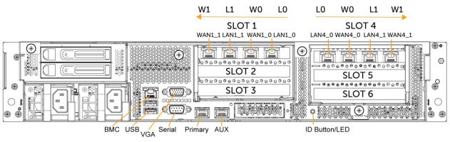
Figure: Slot locations and port numbering for 2U xx90 appliances shows the slot and port numbering for xx90 appliances. The interface names are a combination of LAN/WAN port and slot number. For example, the interface names for slot 4, from left to right, are LAN4_0, WAN4_0, LAN4_1, WAN4_1.
Slot locations and port numbering for 2U xx90 appliances
Slot and port numbering for 2U xx80
On SteelHead 2U xx80 and Interceptor 9800 appliances, the NIC riser assembly attaches to the motherboard between the two columns of slots. When facing the rear of the chassis:
• slots 1 to 3 are on the left, the port numbering for these cards ascends from right to left.
• slots 4 to 6 are on the right, the port numbering for these cards ascends from left to right.
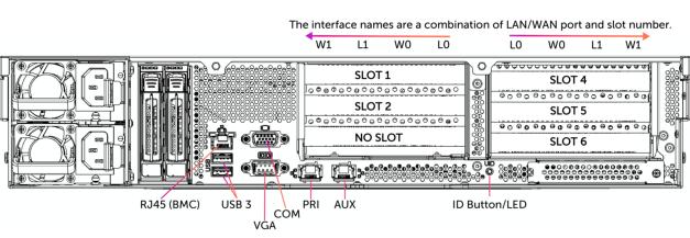
Figure: Slot locations and port numbering for SteelHead 2U xx80 and Interceptor 9800 appliances shows the slot and port numbering for xx80 and 9800 appliances. The interface names are a combination of slot and port number. For example, the interface names for slot 4, from left to right, are LAN4_0, WAN4_0, LAN4_1, WAN4_1.
Slot locations and port numbering for SteelHead 2U xx80 and Interceptor 9800 appliances
Installing NICs in 2U appliances
1. Power down the appliance.
2. Remove the power-supply cord.
3. Remove the cables connected to the appliance.
4. Remove the appliance from the mounting rack, if necessary.
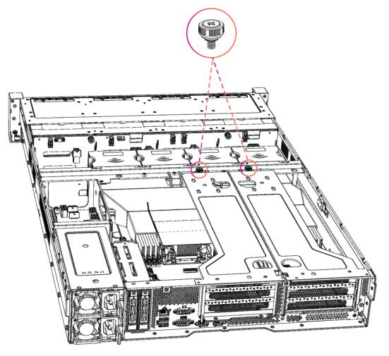
Loosening the riser bracket locking screw in 2U xx90 appliances
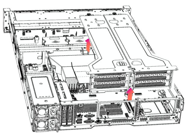
Lifting the riser brackets out of the 2U xx90 chassis
Removing the dummy bracket
9. Hold the new card between the front bezel and the rear of the card to avoid ESD damage.
Installing the PCI riser assembly
11. Carefully turn over the riser bracket and insert it into the guide pins on the chassis.
13. Replace the cover on the chassis.
14. Connect the cables.
For appliances with attached storage units, reconnect the replacement NIC's SAS cable to the storage RAID cards before inserting the NIC into the slot.
15. Connect the power cords.
16. Power up the appliance and check the status lights.
About 1U slot and port numbering
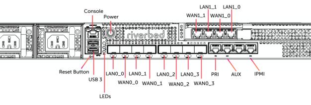
Slot and port numbering for 1U 4090 appliances
The 1U xx90 appliance ships with one add-on Four-Port 1-GbE Copper Base-T (410-00115-01) NIC installed in Slot 1 (WAN1_1, LAN1_1, WAN1_0, LAN1_0).
The Slot 0 ports (LAN0_0, WAN0_0 through LAN0_3, WAN0_3) do not support fail-to-bypass; consult the following table for expected behavior:
t
Condition | Traffic Behavior |
|---|
Optimization is enabled on the in-path and the optimization service is running | Traffic is intercepted or passed through as usual per the in-path rule table. |
Optimization is disabled on the in-path interface, but the optimization service is running on the appliance | Traffic is passed through. |
RIOS is not up | Traffic is blocked. |
RIOS is up, but the appliance optimization service is disabled or not running | Traffic is passed through. |
Slot locations and port numbering for the 1U xx90 appliance with included
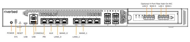
Slot and port numbering for 1U 3080 appliances
The 1U 3080 appliance supports one add-on NIC.
Figure: Slot locations and port numbering for the 1U 3080 appliance with Four-Port Fiber NIC installed shows the slot and port numbering for a 1U 3080 appliance, with an optional Four-Port Fiber NIC installed.
Slot locations and port numbering for the 1U 3080 appliance with Four-Port Fiber NIC installed
Installing NICs in 1U xx90 appliances
1. Power down the appliance. Remove the power-supply cord and any cables connected to the appliance.
2. Remove the appliance from the mounting rack if necessary.
Removing the riser bracket in 1U xx90 appliances
5. Carefully lift the riser bracket assembly from the chassis.
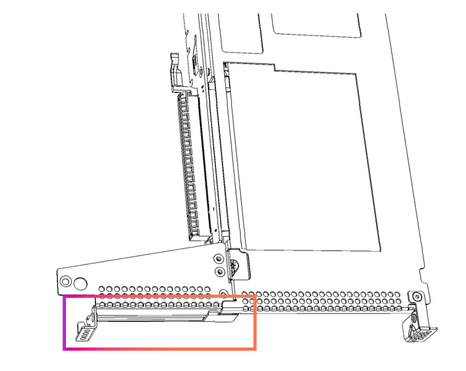
Placeholder bracket in riser bracket assembly for 1U xx90 appliances
Riser assembly connectors
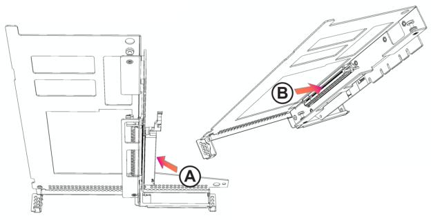
Inserting the NIC into the riser bracket
Make sure the NIC is seated properly in the pin connector. If it isn’t seated properly, the card won’t function properly.
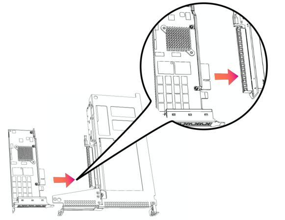
9. Insert the riser bracket straight down, aligning its pins with the motherboard’s pin connector. Make sure the assembly is completely inserted into the motherboard.
Inserting the riser
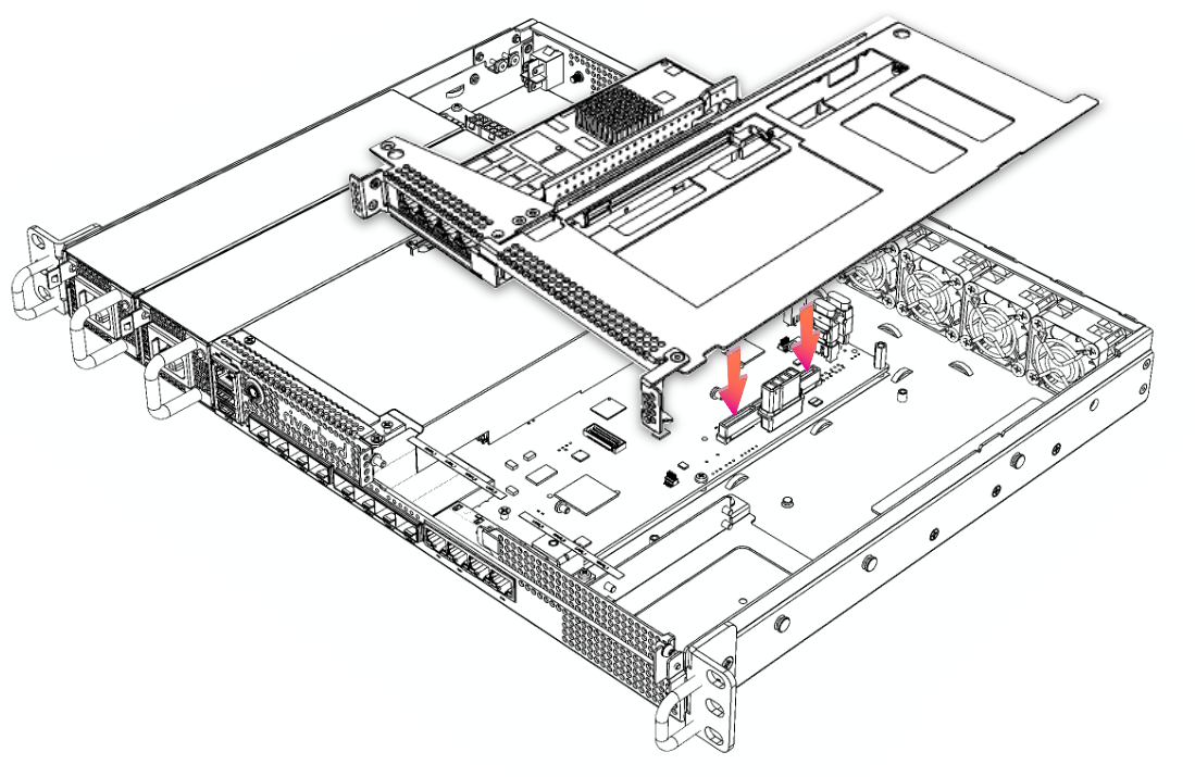
bracket into the 1U xx90 chassis
11. Replace the cover on the chassis.
12. Connect the power cords.
13. Connect the cables.
Installing NICs in 3080 appliances
1. Power down the appliance.
2. Remove the power-supply cord.
3. Remove the cables connected to the appliance.
4. Remove the appliance from the mounting rack.
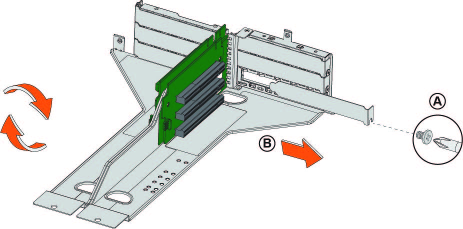
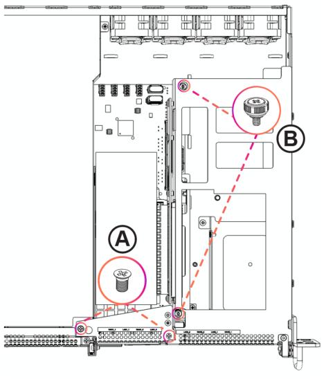
Removing the screws from the NIC riser bracket
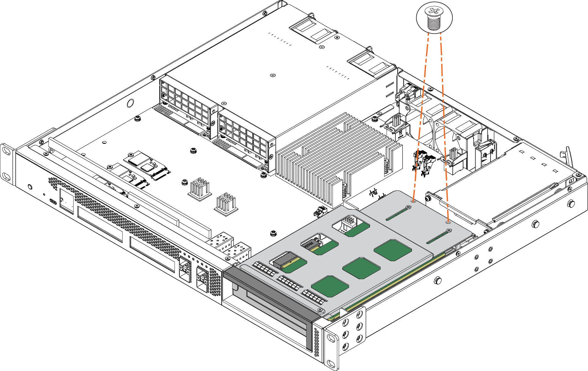
8. Lift the NIC riser bracket straight up to disconnect it from the motherboard.
Removing the NIC riser bracket
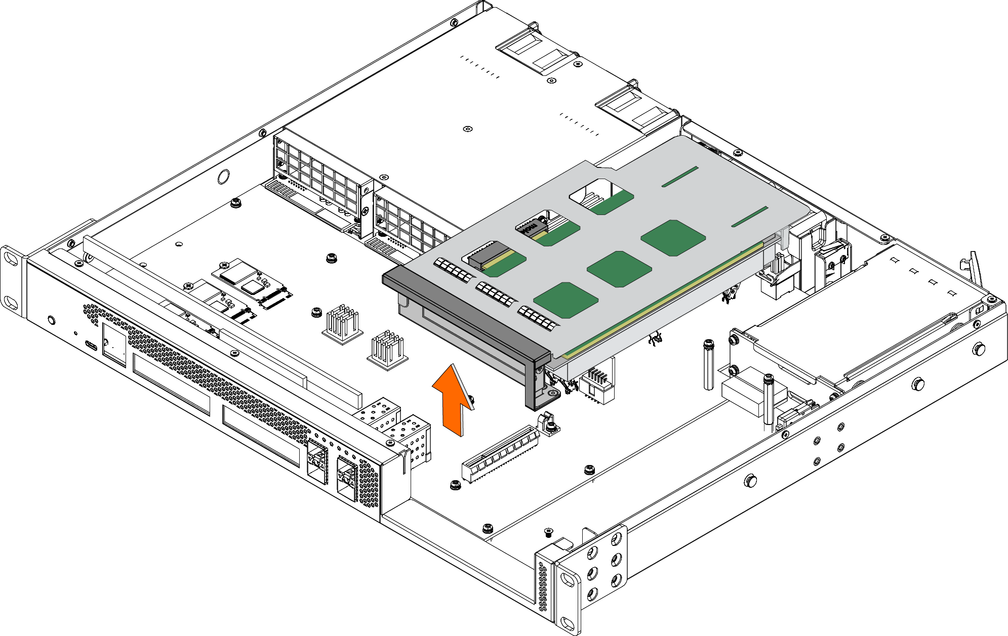
9. Turn over the NIC riser bracket.
Turning over the NIC riser bracket
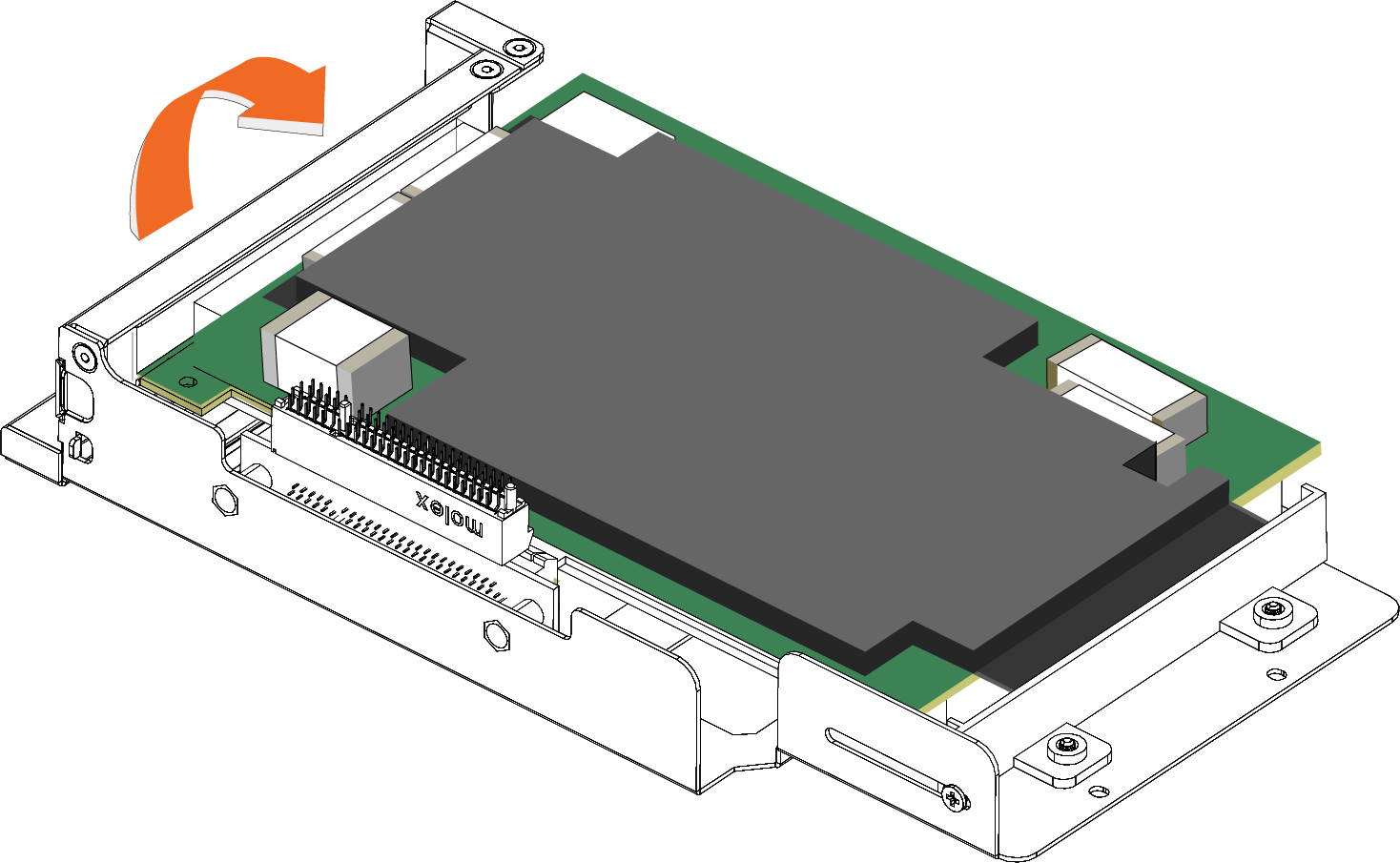
10. To replace an existing NIC, loosen the three screws that secure the card and press the bracket toward you.
Loosen the three screws and press the bracket toward you
11. Slide the NIC out of the pin connector and gently lift and pull the card away from the front of the card holder to remove it.
Removing the card from the pin connector
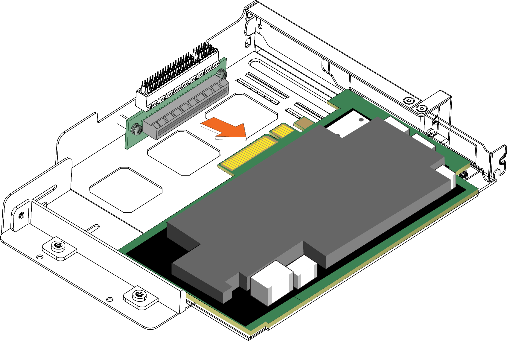
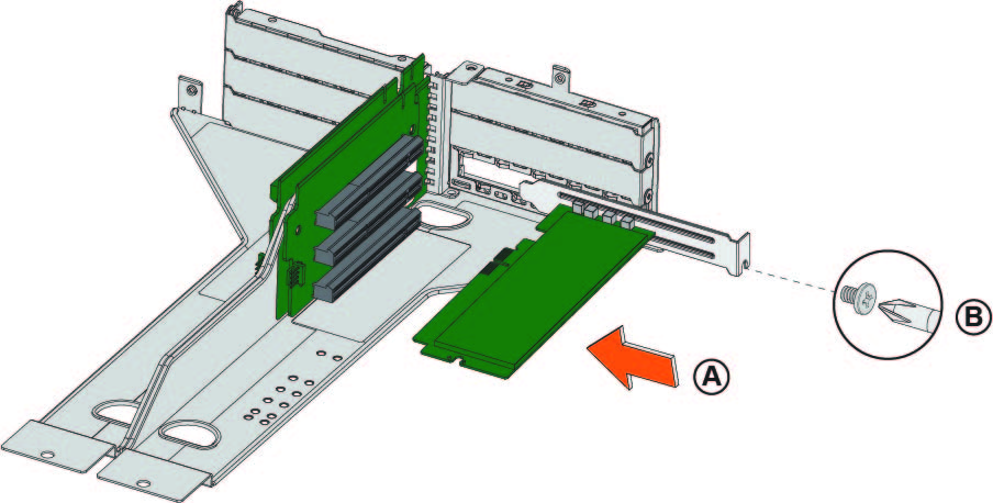
12. Hold the new NIC between the front bezel and the rear of the card to avoid ESD damage.
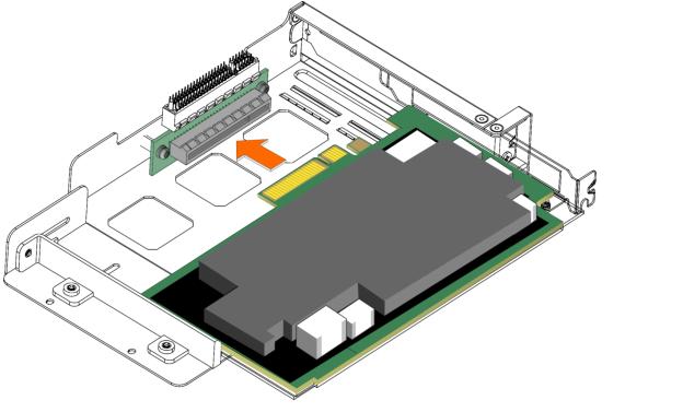
13. Slide the NIC into the card holder.
Installing the new NIC
14. Screw the faceplate into the holder to secure the add-on card.
Securing the faceplate
Make sure the NIC is seated properly in the pin connector. If it isn’t seated properly, the card won’t function properly.
15. Press the bracket on the right side of the card holder toward you to position the card in the holder.
16. Turn the card holder over.
17. Press the card cover straight down into the motherboard’s pin connector. Make sure the card is completely inserted into the motherboard.
Inserting the PCIe card holder into the motherboard
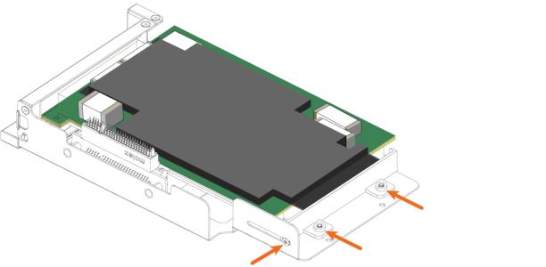
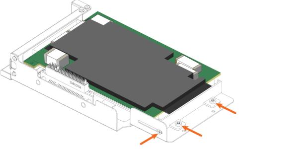
18. Secure the NIC riser bracket with the two screws.
Securing the NIC riser bracket
19. Replace the cover on the chassis. For details, see
Step 5.
20. Connect the power cords.
21. Connect the cables.
22. Power up the appliance and check the status lights.
About 1U 2180 slot and port numbering
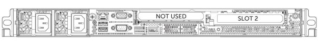
The 1U 2180 appliance supports one add-on NIC, installed in slot 2.
Figure: Slot locations for the 1U 2180 appliance shows the slot locations on the front of the 1U 2180 appliance.
Slot locations for the 1U 2180 appliance
Installing NICs in 2180 appliances
This section describes how to install NICs in 2180 appliances.
1. Power down the appliance.
2. Remove the power-supply cord.
3. Remove the cables connected to the appliance.
4. Remove the appliance from the mounting rack, if necessary.
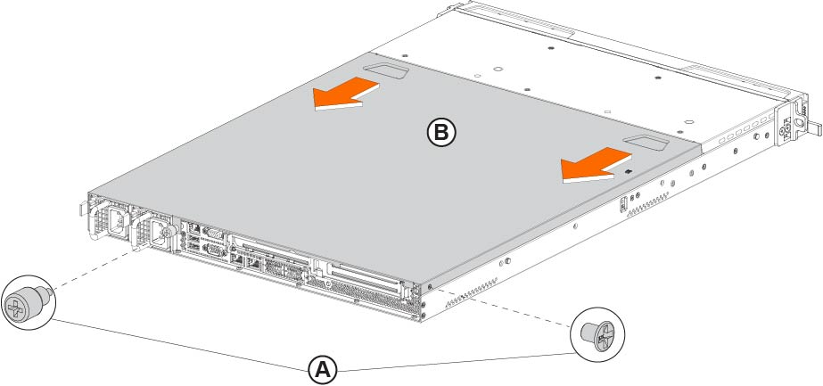
Removing the cover on the 2180 appliance
6. Unscrew the two screws securing the riser to the chassis.
Removing the NIC riser
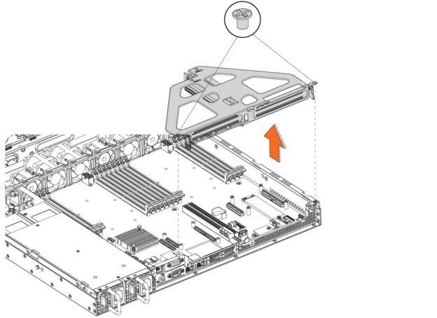
7. Lift up to remove the riser from the chassis.
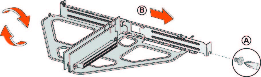
8. If you are replacing an existing card, carefully remove the screw and pull the card from the riser.
Removing the dummy bracket
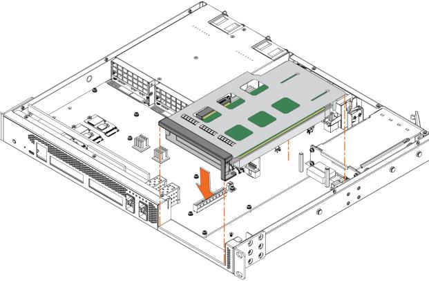
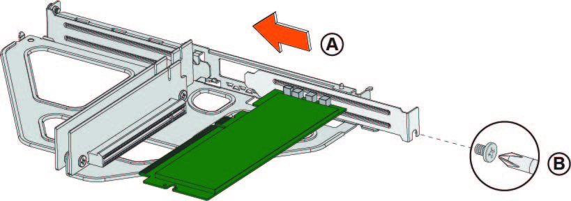
10. Hold the new card between the front bezel and the rear of the card to avoid ESD damage.
Inserting the card into the riser card bracket
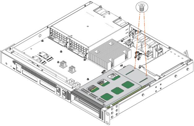
Inserting the riser card bracket into the chassis
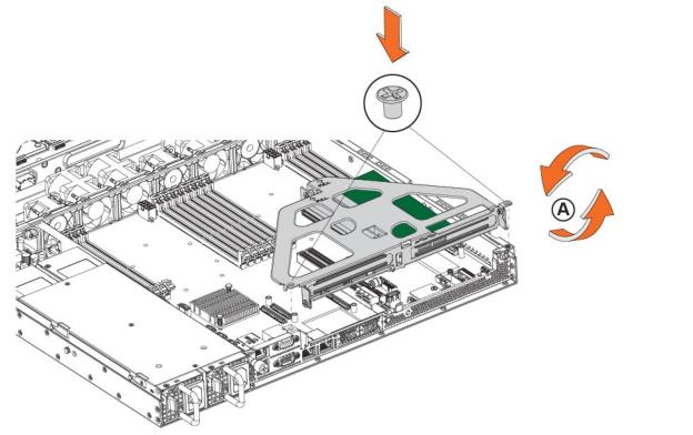
13. Replace the cover on the chassis.
Do not secure the rear side screw; it will prevent you from opening the cover when the appliance is installed in a rack.
14. Connect the power cords.
15. Connect the cables.
16. Power up the appliance and check the status lights.
Enabling Two-Port 10-GbE NICs in the 4280-DP and 2280 appliances
For the Two-Port 10-GbE Fiber SFP+ NIC (NIC-1-010G-2SFPP) to work properly in the NetProfiler 4280-DP and SteelCentral Flow Gateway 2280 appliances, you must deactivate the 1-GbE interfaces and enable the 10-GbE interfaces. For detailed instructions on configuring these interfaces, go to Knowledge Base article
S33947.
Verifying NIC installation
1. Connect to the RiOS CLI. For detailed information about the CLI, see the Riverbed Command-Line Interface Reference Manual.
2. Enter enable mode. At the system prompt, enter the enable command:
amnesiac > enable
amnesiac #
3. Verify that the NIC is correctly installed. At the system prompt enter the show hardware all command:
amnesiac # show hardware all
Hardware revision: A
Mainboard: Platform snook 1U 2.5, 425-00060-03
Slot 0: .......... Onboard I350 4 Port Copper GigE Network Bypass Module, Integrated
Slot 1: .......... 4 Port SR Fiber 10 GigE Bypass Network Card, 410-00191-01
System led: Green
You can run the in-path reset-iface command in configuration mode to reset the main interface and recognize all ports.
NIC self-test
The following self-test helps you verify that your card functions properly.
Before you begin, connect a crossover cable between the LAN and WAN ports on the SteelHead. Once the service is enabled and the inpath0_0 interface has an IP address, both interfaces should show a link. Check the Link/Activity, Bypass, and Disconnect/Block LEDs on the card to verify connectivity. For more information about the LEDs, see
Reference: NIC Lights, Ports, Specifications.You must induce traffic to ensure that the card works correctly. Removing the cable from the ports turns off the LEDs.
1. Connect to the RiOS CLI.
2. To check for connectivity, at the system prompt, enter the following ping command:
amnesiac > ping -c 1 -I <inpath-ip-address> -b <broadcast-ip-address>
For example (where the netmask is /24):
amnesiac > ping -c 1 -I 10.11.128.8 -b 10.11.128.255
This ping command creates a loop for testing the SteelHead in isolation.
Troubleshooting NIC installation
The following diagnostic tips address common fixable issues:
Unseated card—Sometimes cards can become unseated during shipment. This can lead to system malfunctions, including system reboots. To correct this situation, power down the system and reseat the card.
For SteelHead appliances:
Configuration issue—Make sure the speed and duplex match on the SteelHead and its connected devices.
Wiring issue—Make sure you have a crossover cable for the connection between the SteelHead and a router. Use a straight-through cable for the connection between the SteelHead and a switch port.