Replacing 1U Appliance Components
This chapter describes how to replace hard disk drives (HDDs), solid-state drives (SSDs), memory modules, fans, and power supply units in 1U appliances.
Use caution when you remove or replace components; they can become hot to the touch.
About required tools
You need the following tools and equipment to replace appliance components:
• You must use approved components for the appliance to function properly. Installation of unapproved components will result in boot failure. To order components, contact Support at https://support.riverbed.com.
• Use the Riverbed magnetic reversible screwdriver (that is, Phillips-head and flathead) enclosed with your shipment to remove screws in the appliance. The magnetic screwdriver ensures screws aren’t lost in the appliance.
• When you replace appliance components, you must wear a grounded ESD antistatic strap to protect the hardware against electrostatic discharge. Make sure that the strap makes skin contact prior to handling equipment.
Replacing components in 1U xx90 appliances
This section describes how to replace components such as the chassis cover and power supplies in 1U xx90 appliances.
Removing the chassis cover on 1U xx90 appliances
1. Power down the appliance and unplug all peripheral devices and the power cable.
Removing the 1U xx90 chassis cover rear screws
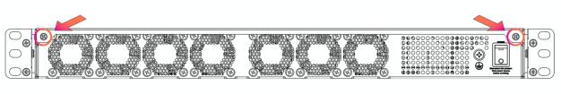
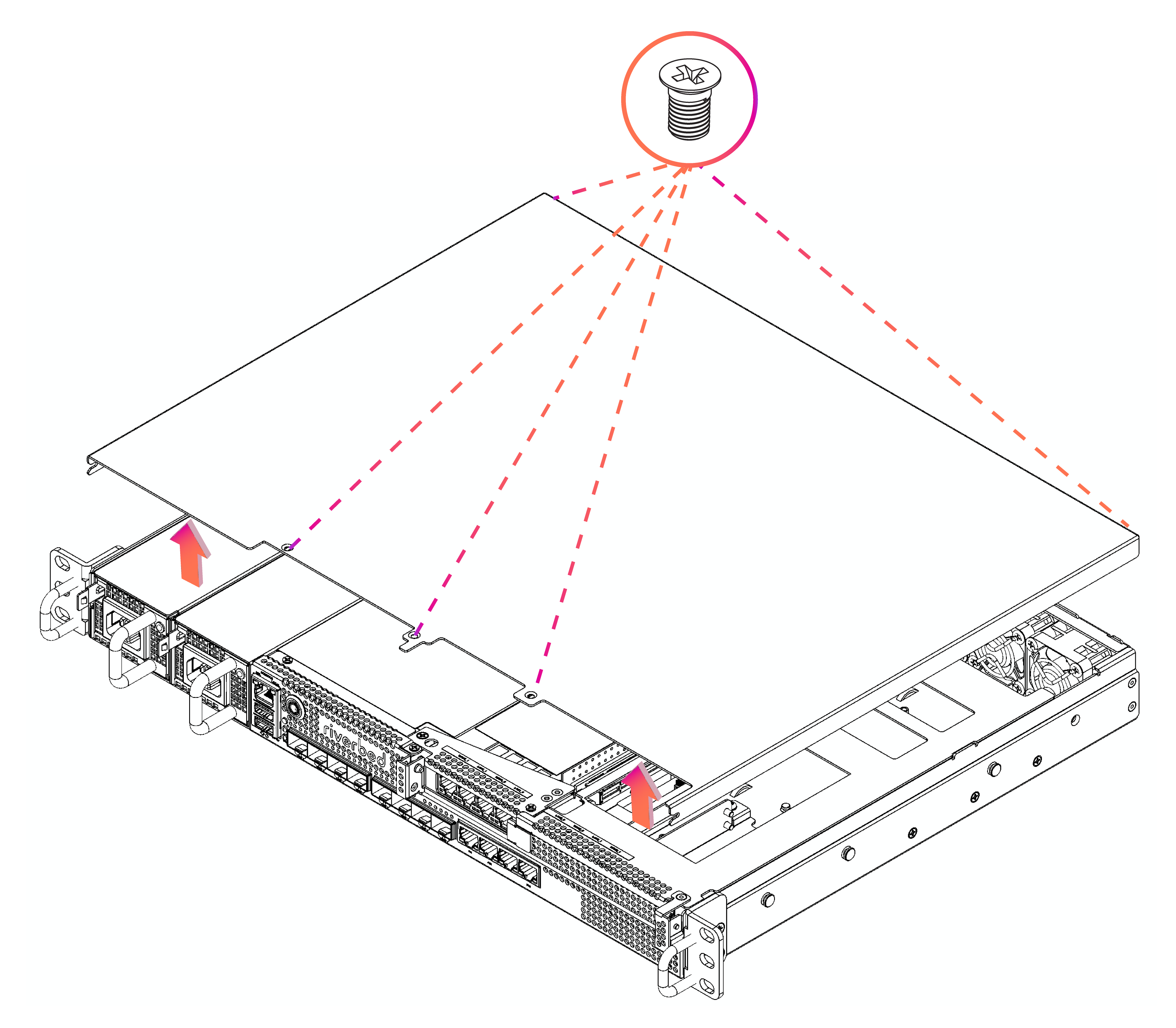
Removing the screws and chassis cover on the 1U xx90 appliance
If the Intelligent Platform Management Interface (IPMI) alarm triggers when you open the chassis cover, enter the clear hardware error-log command in the CLI to clear the alarm. For details, see the Riverbed Command-Line Interface Reference Manual.
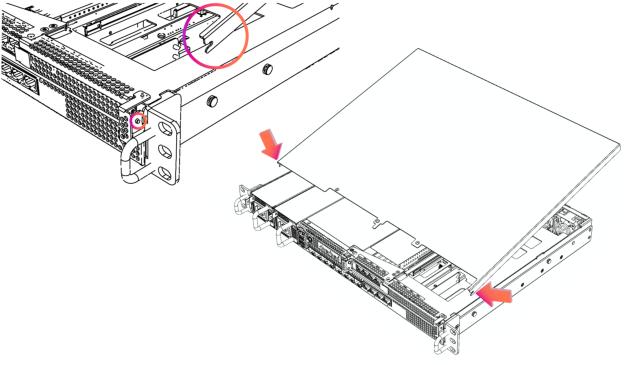
Replacing the chassis cover on 1U xx90 appliances
Replacing power supply units in 1U xx90 appliances
The 1U xx90 appliances have replaceable, hot-swappable power supply units. Facing the front of the appliance, PSU1 is on the left and PSU2 is on the right.
1. Locate the defective power supply unit and remove the power cord.
Removing the power supply unit from the 1U xx90 appliances
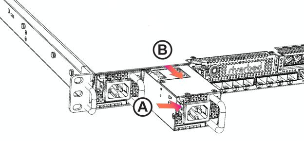
3. On the new power supply unit, pushing the unit into the chassis until it clicks.
4. Plug the AC power cord into the new power supply unit.
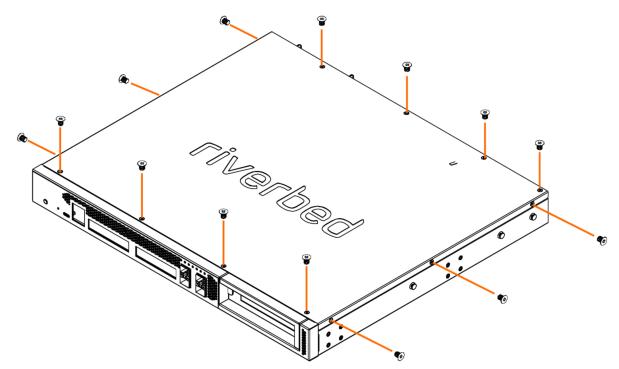
Removing the chassis cover on 3080 appliances
1. Power down the appliance and unplug all peripheral devices and the power cable.
2. Facing the back of the appliance, remove the 14 screws from the appliance: four on the front and back, and three on the right and left side.
Removing the screws on the 3080 appliance
Removing the cover on the 3080 appliance
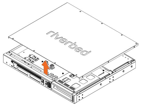
If the Intelligent Platform Management Interface (IPMI) alarm triggers when you open the chassis cover, enter the clear hardware error-log command in the CLI to clear the alarm. For details, see the Riverbed Command-Line Interface Reference Manual.
Replacing Internal Datastore SSDs in 3080 appliances
2. The 3080 appliance has two internal SSD cards inside the appliance. Remove the locking screw of the SSD you want to replace.
Removing the SSD locking screw in the 3080 appliance
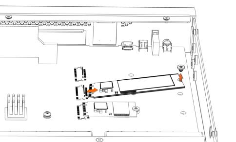
3. Holding each side of the SSD, carefully pull the SSD from the pin connector.
4. Insert the new SSD into the pin connector.
Inserting the drive into the pin connector in the 3080 appliance
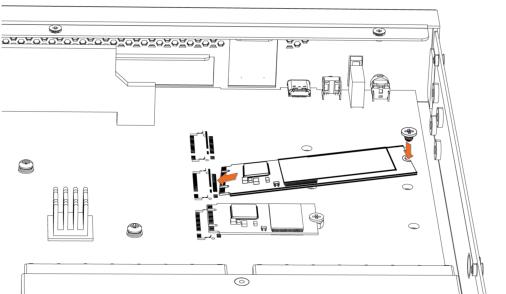
5. Press the SSD down and insert the locking screw.
6. Replace the chassis cover.
Replacing the rear management drives (HDD or SSD) in 3080 appliances
The 3080 appliance has two replaceable, hot-swappable management drives located at the back of the appliance. When replacing a drive, replace only one drive at a time. These drives can be all HDD, all SSD, or a mixed configuration of both with the following restrictions:
• If the system is populated with both management drives as SSD, a failed SSD can be replaced with either an SSD or HDD.
• If the system is populated with both management drives as HDD, a failed HDD must be replaced with an HDD only.
• If the system is operating with a mixed SSD and HDD configuration:
– a failed HDD can be replaced with either an SSD or HDD.
– a failed SSD must be replaced with an HDD.
• Support for SSD management drives requires a minimum of the following RiOS software versions:
– 9.12.2c-ssd1
– 9.14.2c-ssd1
– 9.15.1-ssd1
– 9.16.0
1. To unlock a drive, use a screwdriver to turn the screw head on the drive 90 degrees to the left.
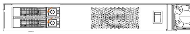
Unlocking a rear drive on a 3080 appliance
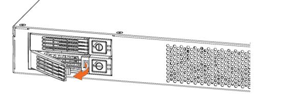
2. Press the lock-lever button. The drive snaps open.
Removing a rear drive on a 3080 appliance
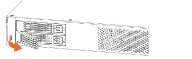
3. Slide the faulty disk drive tray out.
4. Replacement drives are shipped in their carrier cases. Slide in the new disk drive until it engages with the back connectors in the chassis.
5. Push in to secure the locking lever until it clicks into place. The disk drive LED lights green when connected.
Securing the locking lever
6. To lock the drive, turn the screw head on the drive 90 degrees to the right.
For SteelHead appliances, the new disk drive automatically performs a self-test and begins working with the other drives without any setup or configuration. Rebuilding the drive can take 3 to 4 hours, depending on system load. You can configure the web interface to send an email notification to the administrator once the rebuild is complete.
Replacing memory modules in 3080 appliances
Always use Riverbed-approved memory modules. Replacing the existing memory module with a module of a different size causes the appliance to fail.
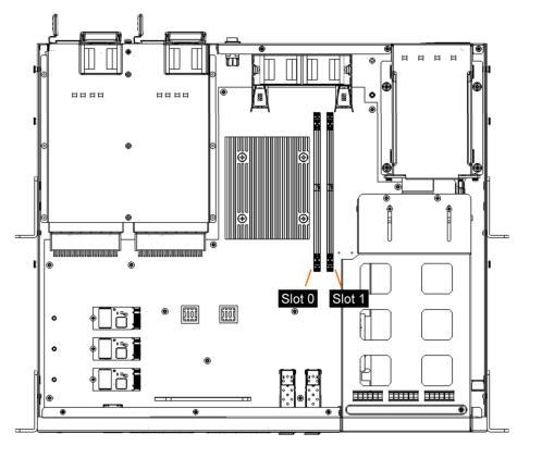
2. The 3080 appliance has two dual in-line memory module (DIMM) slots: slot 0 and slot 1. When replacing memory on the appliance, place the new memory module in the slot from which the faulty memory module was removed.
Memory module slot locations in the 3080 appliance
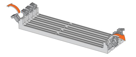
3. Press the locking clips outward to unlock them and gently pull the memory module out of the slot.
Releasing the locking clips
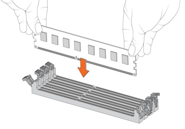
4. Align the memory-module edge connector and insert it into the slot. When inserted properly, the memory slot locking levers lock automatically onto the indentations at the ends of the module.
Inserting the memory modules
5. Press the clips inward to lock the module in place.
6. Ensure that all clips are in the upright locked position.
7. Replace the chassis cover.
8. Reattach the power cords and peripherals.
9. Power on the appliance.
Replacing fans in 3080 appliances
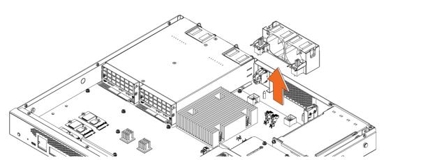
2. The 3080 appliance has two fans contained in a single fan unit. To remove the fan unit, pull straight up on each side of the unit.
Removing the fan unit in 3080 appliances
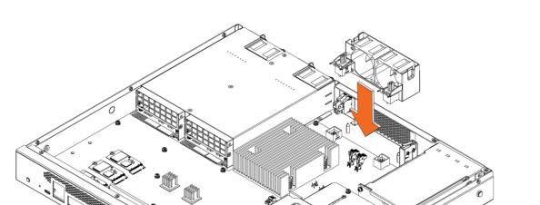
3. Insert the new fan unit into the slot.
Inserting the new fan unit
4. Replace the chassis cover.
You can see fan status by using the show stats fan command. The output and number of fans vary depending on your appliance. On appliances where each fan has two rotors, each rotor has a unique status entry. For details, see the Riverbed Command-Line Interface Reference Manual.
Replacing power supply units in 3080 appliances
Removing the power supply unit from the 3080 appliances
4. On the new power supply unit, make sure the lock handle is up then press and hold the orange latch while pushing the unit into the chassis.
5. Press the lock handle down.
6. Plug the AC power cord into the new power supply unit.
Replacing components in 2180 appliances
This section describes how to replace components in the 1U 2180 appliance.
Removing the chassis cover on 2180 appliances
1. Power down the appliance and unplug all peripheral devices and the power cable.
Removing the chassis cover on 2180 appliances
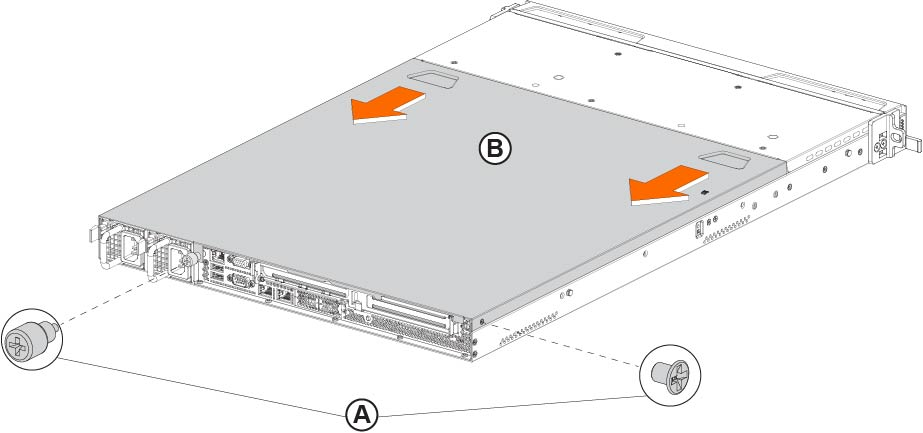
Place your thumbs on the recessed tabs (see
Figure: Removing the chassis cover on 2180 appliances, letter B), and slide the cover straight back and up.
Replacing HDDs in 2180 appliances
The 2180 appliances include four hot-swappable HDDs (see
Figure: 2180 disk drive numbers).
2180 disk drive numbers

1. Remove the bezel.
2. Identify the faulty disk drive. The disk drive LED is red for failed drives.
3. Press the orange locking-lever latch and pull the locking lever open.
4. Slide the faulty disk drive tray out.
5. Slide in the new disk drive until it engages with the back connectors in the chassis.
6. Push to secure the locking lever until it clicks into place. The disk drive LED lights green when connected.
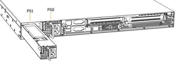
Replacing power supply units in 2180 appliances
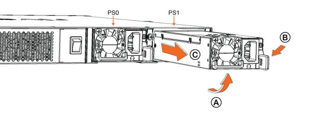
The 2180 appliances have two replaceable, hot-swappable power supply units. Facing the rear of the appliance, PS1 is on the left and PS0 is on the right (see
Figure: Removing power supply units from 2180 appliances).
1. Locate the defective power supply unit and remove the power cord.
2. Press the latch and pull the power supply unit toward you, sliding it out of the chassis. Put the defective power supply unit aside; wait until it cools down before touching it.
Removing power supply units from 2180 appliances
3. Press and hold the latch and push the new power supply into the chassis using the handle.
4. Plug the AC power cord into the new power supply unit.
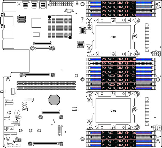
Replacing memory modules in 2180 appliances
Always use Riverbed-approved memory modules. Replacing the existing memory module with a module of a different size causes the appliance to fail.
Memory module slot locations in 2180 appliances
1. Power down the appliance.
2. Remove the chassis cover.
4. Align the memory-module edge connector and insert it into the slot. When inserted properly, the memory slot locking levers lock automatically onto the indentations at the ends of the module.
6. Replace the chassis cover.
7. Reattach the power cords and peripherals.
8. Power on the appliance.
Replacing fans in 2180 appliances
1. Power down the appliance.
2. Remove the chassis cover.
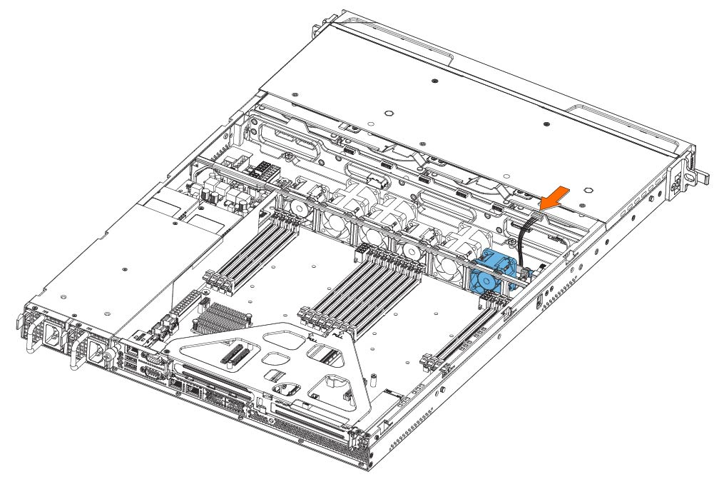
3. Identify the faulty fan.
4. Unplug the fan cable located on the HDD backplane.
Unplugging the fan cable
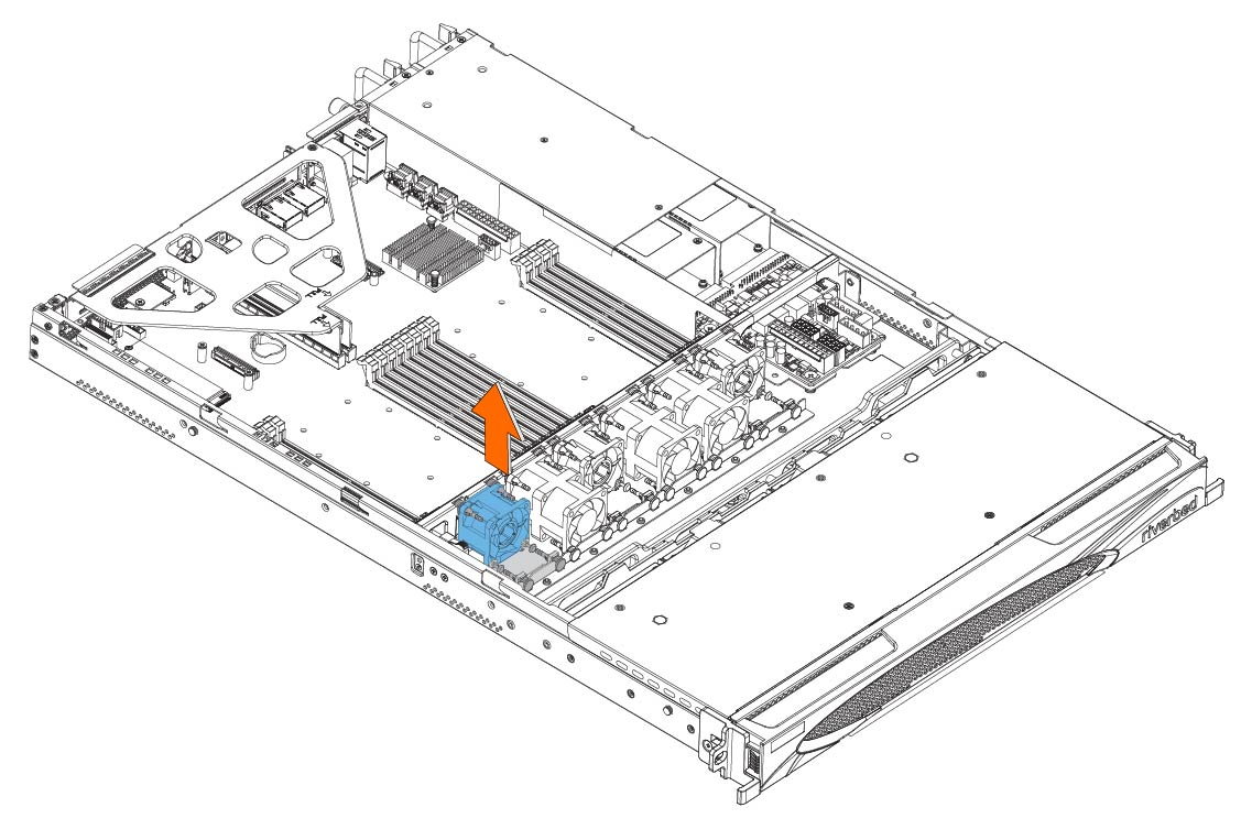
5. To remove the fan, including the attached flat metal fan bracket, pull straight up on each side of the fan.
Removing the fan
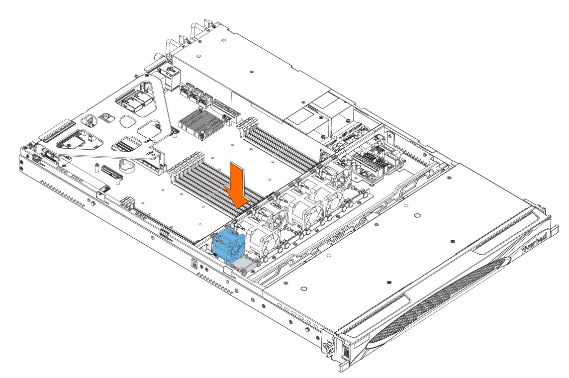
6. Insert the new fan with the attached bracket into the fan slot.
Inserting the new fan
7. Plug the fan cable into the HDD backplane.
8. Replace the chassis cover.