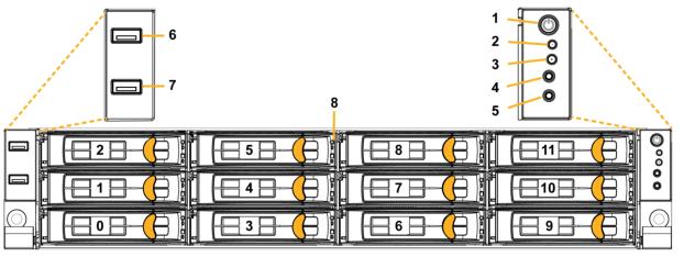
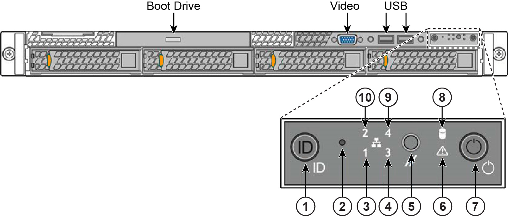
2U xx90 front panel with LEDs and buttons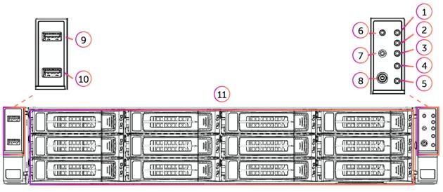
Reference | LED/button | Description |
|---|---|---|
1 | Primary (PRI) LED | Link = Green Activity = Blinks green No link = No light |
2 | Auxiliary (AUX) LED | Link = Green Activity = Blinks green No link = No light |
3 | ID LED | On = Blue (System identified remotely on the server.) Off = Off (System not identified.) |
4 | Warning LED | System normal = Off System fault = Solid red |
5 | HDD LED | Not used. |
6 | Reset Button | Press to reboot the appliance. |
7 | System ID Button | Press the system ID button when the system AC (Alternating Current) is on. The system ID LED indicates the system is identified with a blue light. Users from a remote site can activate the ID LED by inputting commands in IPMI. For details, contact Riverbed Support at https://support.riverbed.com. |
8 | Power On/Off Button | |
9, 10 | USB3.2 Gen.1 ports | |
11 | HDD/SSD LEDs | Activity LED (lower light) Link = Green (Drive present, with no activity.) Activity = Blinks green (Drive present, with activity.) Status LED (upper light) Failed Disk = Solid red |
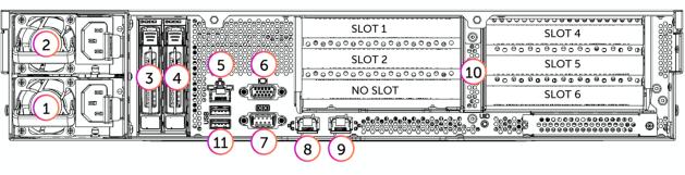
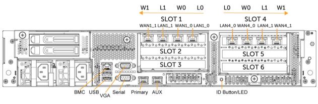
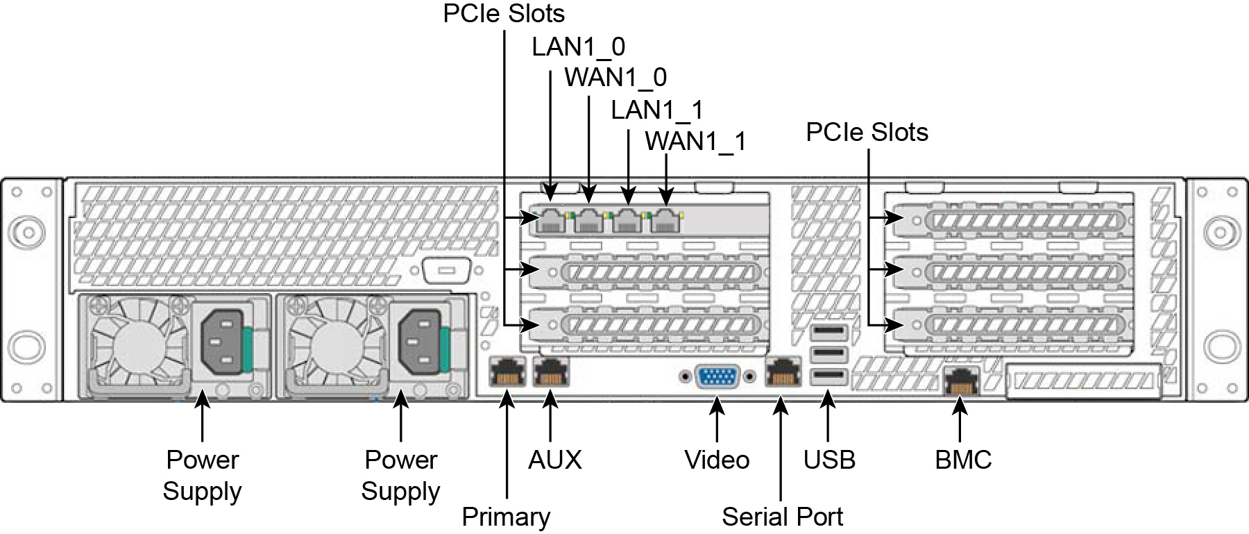
Reference | LED/button |
|---|---|
1 | PSU 0 |
2 | PSU 1 |
3, 4 | HDD/SSD |
5 | Management (MGMT) Port |
6 | VGA Port |
7 | COM Port |
8 | Primary (PRI) Port |
9 | Auxiliary (AUX) Port |
10 | PCIe Expansion Slot (Gen5 x8/16) |
11 | USB3.2 Gen.1 ports |
xx90 Family | |
|---|---|
Form factor | 2U |
Processor | Intel Xeon Processor Scalable Families |
Chipset | Intel C741 |
Memory | 8 Memory channels per CPU 8 + 8 RDIMM slots Up to 512 GB RDIMM |
PCIe expansion slots | 2 PCI-E Gen5 x 16 slots 2 PCI-E Gen5 x 8 slots 1 PCI-E Gen5 x 4 slots |
Network | 10 GbE ports, 1 PHY dedicated for IPMI |
External IO | RJ45 BMC 2 RJ45 10GBase-T (Intel X710-AT2) 2 USB3.2 Gen.1 ports (at rear) 2 USB3.2 Gen.1 ports (at front) DB9 COM Port VGA Port |
Form factor | 2U rack mountable chassis Dimensions: 27.56" x 17.26" x 3.42" 700 x 438.5 x 87 mm |
System Power | 2 x 1300 Watt PSU Input 100-127V~, 12A, 50/60 Hz 200-240V~, 8.5A, 50/60 Hz |
Cooling System | Four (4) 8cm fans |
Storage | 12 x 3.5/2.5 inch hot swap HDD/SSDs with 4x NVMe (Front) 2 x 2.5 inch hot swap SATA/NVMe SSDs (Rear) |
Temperature | Operating Temp: 10°C to 40°C Non-operating Temp: Minus 40°C to 70°C Humidity: 90%, non-condensing at 40°C |
Model | CXA-08090 | CXA-06090 | NP-04290 | FG-02290 | ||||
|---|---|---|---|---|---|---|---|---|
Chassis | 2U | 2U | 2U | 2U | 2U | 2U | 2U | 2U |
PSU Type | 2x 1300W | 2x 1300W | 2x 1300W | 2x 1300W | 2x 1300W | 2x 1300W | 2x 1300W | 2x 1300W |
Input Power | 100-127VAC | 200-240VAC | 100-127VAC | 200-240VAC | 100-127VAC | 200-240VAC | 100-127VAC | 200-240VAC |
AC Input | 120VAC | 230VAC | 120VAC | 230VAC | 120VAC | 230VAC | 120VAC | 230VAC |
Max. Amps | 6.0 | 3.1 | 4.6 | 2.4 | 5.7 | 3.0 | 3.3 | 1.7 |
Max. Watts | 714 | 723 | 560 | 542 | 683 | 671 | 392 | 382 |
Typ. Watts | 572 | 579 | 448 | 434 | 547 | 537 | 314 | 306 |
Max. VA | 722 | 730 | 572 | 554 | 690 | 684 | 396 | 403 |
Power Factor | 0.99 | 0.99 | 0.98 | 0.98 | 0.99 | 0.98 | 0.99 | 0.95 |
BTU | 1949 | 1973 | 1528 | 1480 | 1864 | 1830 | 1070 | 1043 |
Model | SCAN-08190 | SCAN-04190 | SCAN-02190 | |||
|---|---|---|---|---|---|---|
Chassis | 2U | 2U | 2U | 2U | 2U | 2U |
PSU Type | 2x 1300W | 2x 1300W | 2x 1300W | 2x 1300W | 2x 1300W | 2x 1300W |
Input Power | 100-127VAC | 200-240VAC | 100-127VAC | 200-240VAC | 100-127VAC | 200-240VAC |
AC Input | 120VAC | 230VAC | 120VAC | 230VAC | 120VAC | 230VAC |
Max. Amps | 6.5 | 3.3 | 5.1 | 2.7 | 3.3 | 1.7 |
Max. Watts | 771 | 780 | 614 | 602 | 398 | 389 |
Typ. Watts | 617 | 614 | 491 | 481 | 319 | 311 |
Max. VA | 779 | 788 | 620 | 614 | 402 | 409 |
Power Factor | 0.99 | 0.99 | 0.99 | 0.98 | 0.99 | 0.95 |
BTU | 2103 | 2127 | 1676 | 1641 | 1087 | 1060 |
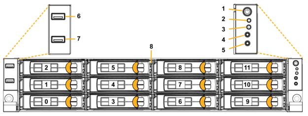
Reference | LED or button | Description |
|---|---|---|
1 | Power On/Off Button and Integrated LED | On = Green (System is turned on.) Sleep State = Green (System is in S1 or S3 sleep state.) Off = No light (Power is off.) |
2 | IPMI Warning LED | The IPMI Warning LED shows the current health of the server system. Normal = Green (No failures) Degraded/Warning = Amber (Indicates fan failure, high temperature, over voltage, or power supply failure.) Critical = Blinking amber and green (Indicates a problem that needs attention, such as optimization service down, no license, or in_path is not enabled for optimization service.) |
3 | ID LED | On = Blue (System identified remotely on the server.) Off = Off (System not identified.) |
4 | Reset Button | Press to reboot the appliance. |
5 | System ID Button | Press the system ID button when the system AC (Alternating Current) is on. A blue LED light identifies the system. Users from a remote site can activate the ID LED by inputting commands in IPMI. For details, contact Support at https://support.riverbed.com. |
6, 7 | USB Ports v2.0 | |
8 | HDD/SSD LEDs | Activity LED (lower light) Link = Green (Drive present, with no activity.) Activity = Blinks green (Drive present, with activity.) Status LED (upper light) Failed disk = Solid red |
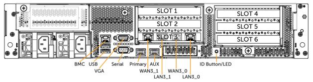
LED or button | Description |
|---|---|
ID LED/Button | On = Blue (System identified remotely on the server.) Off = Off (System not identified.) Press the system ID button when the system AC (Alternating Current) is on. A blue LED light identifies the system. Users from a remote site can activate the ID LED by inputting commands in IPMI. For details, contact Support at https://support.riverbed.com. |
Primary and AUX Port LEDs | Left LED Link = Green Activity = Blinks green No Link = Off Right LED 10 Mbps = Off 100 Mbps = Green 1000 Mbps = Amber |
Four-Port 1 GbE Copper Bypass Card LEDs (preinstalled) | Link/Activity LED Link = Green Activity = Blinks green Speed/Bypass/Disconnect LED 1000 Mbps = Yellow 100 Mbps = Green 10 Mbps = Off Bypass = Blinks green Disconnect = Blinks yellow |
Power Supply LEDs | Power on and healthy = Green Standby = Blinks green Power off = Off Unplugged or power lost but second power supply has power = Amber (for about 5 seconds) then turns Off Power on with warning = Blinks amber (indicates high temperature, high power, high current, or slow fan) |
Specification | 5080 | 7080 |
|---|---|---|
Form factor | 2U | 2U |
Memory | 32 GB (4 x 8 GB) | B010 = 64 GB (8 x 8 GB) B020 = 96 GB (12 x 8 GB) B030 = 192 GB (12 x 16 GB) |
HDD | 2 x 1 TB | 2 x 1 TB |
SSD | 6 x 240 GB | B010 = 6 x 480 GB B020 = 8 x 480 GB B030 = 8 x 960 GB |
Data store | 1.4 TB | B010 = 2.8 TB B020 = 3.8 TB B030 = 7.6 TB |
Dimensions (LxWxH) | 27.56 x 17.32 x 3.43 in. (700 x 440 x 87 mm) | 27.56 x 17.32 x 3.43 in. (700 x 440 x 87 mm) |
Weight (without packaging) | 51 lb (23 kg) | 51 lb (23 kg) |
Voltage | 100-127 V, 200-240 V | 100-127 V, 200-240 V |
PSU | 2 x 770 W 100-127 VAC/10 A, 50/60 Hz 200-240 VAC/5 A, 50/60 Hz | 2 x 770 W 100-127 VAC/10 A, 50/60 Hz 200-240 VAC/5 A, 50/60 Hz |
PCI slots | 6 | 6 |
Included bypass ports/max no. ports | 4/20 | 4/20 |
System | CX 5080 | CX 7080 | CX 7080 | |||
|---|---|---|---|---|---|---|
Configuration | B010 | B010, B020 | B030 | |||
PSU type | 2 x 770 W | 2 x 770 W | 2 x 770 W | |||
AC input | 120 V | 230 V | 120 V | 230 V | 120 V | 230 V |
Max. amps. | 3.2 A | 1.7 A | 3.9 A | 2.0 A | 5.0 A | 2.6 A |
Max. watts | 372 W | 363 W | 467 W | 455 W | 598 W | 574 W |
Typical watts | 298 W | 290 W | 374 W | 364 W | 478 W | 459 W |
Max. volt-ampere | 383 VA | 395 VA | 477 VA | 473 VA | 604 VA | 592 VA |
Power factor | 97 W/VA | 92 W/VA | 98 W/VA | 96 W/VA | 99 W/VA | 97 W/VA |
BTU (typical) | 1015 BTU | 991 BTU | 1275 BTU | 1240 BTU | 1632 BTU | 1566 BTU |
Specification | 5080 | 7080 |
|---|---|---|
Operating acoustic | 56 dB (typical) | 56 dB (typical) |
Temperature (operating) | 32°F to 104°F (0°C to 40°C) | 32°F to 104°F (0°C to 40°C) |
Temperature (storage) | -40°F to 140°F (-40°C to 60°C) | 40°F to 140°F (-40°C to 60°C) |
Relative humidity | 40% to 90%, noncondensing at 40°C | 40% to 90%, noncondensing at 40°C |
Reference | LED or button | Description |
|---|---|---|
1 | Power On/Off Button and Integrated LED | On = Green (System is turned on.) Sleep state = Green (System is in S1 or S3 sleep state.) Off = No light (Power is off.) |
2 | IPMI Warning LED | The IPMI Warning LED shows the current health of the server system. Normal = Green (No failures) Degraded/Warning = Amber (Indicates fan failure, high temperature, over voltage, or power supply failure.) Critical = Blinking amber and green (Indicates a problem that needs attention, such as optimization service down, no license, or in_path is not enabled for optimization service.) |
3 | ID LED | On = Blue (System identified remotely on the server.) Off = Off (System not identified.) |
4 | Reset Button | Press to reboot the appliance. |
5 | System ID Button | Press the system ID button when the system AC (Alternating Current) is on. A blue LED light identifies the system. Users from a remote site can activate the ID LED by inputting commands in IPMI. For details, contact Support at https://support.riverbed.com. |
6, 7 | USB Ports v2.0 | |
8 | HDD/SSD LEDs | Activity LED (lower light) Link = Green (Drive present, with no activity.) Activity = Blinks green (Drive present, with activity.) Status LED (upper light) Failed disk = Solid red |
LED or button | Description |
|---|---|
ID LED/Button | On = Blue (System identified remotely on the server.) Off = Off (System not identified.) Press the system ID button when the system AC (Alternating Current) is on. A blue LED light identifies the system. Users from a remote site can activate the ID LED by inputting commands in IPMI. For details, contact Support at https://support.riverbed.com. |
Primary and AUX Port LEDs | Left LED Link = Green Activity = Blinks green No Link = Off Right LED 10 Mbps = Off 100 Mbps = Green 1000 Mbps = Amber |
Four-Port 1 GbE Copper Bypass Card LEDs (preinstalled) | Link/Activity LED Link = Green Activity = Blinks green Speed/Bypass/Disconnect LED 1000 Mbps = Yellow 100 Mbps = Green 10 Mbps = Off Bypass = Blinks green Disconnect = Blinks yellow |
Power Supply LEDs | Power on and healthy = Green Standby = Blinks green Power off = Off Unplugged or power lost but second power supply has power = Amber for about 5 seconds, and then turns Off Power on with warning = Blinks amber to indicate high temperature, high power, high current, or slow fan. |
LED or button | Description |
|---|---|
Power button LED | Pulse Orange = CPU Sleep Solid Orange = Power ON Blink Green = BIOS Solid Green = Begin OS boot |
A (Top LED) | Blue = OS OK Amber = OS Alarm |
B (Middle LED) | Blinking Blue = Drive Activity Amber = Drive Failure |
IPMI (Bottom LED) | Blue = Appliance OK Amber = Appliance hardware alarm |
RJ45 Console Port | Left = SOL SOL Active = On SOL Inactive = Off Right = LOCAL Cable connected = On Cable disconnected = Off |
Power Supply LEDs | Power off = LED off Standby (Controlled by Power Switch on rear panel.) = 1 Hz blinks green Power on and healthy = Green Power lost but second power supply has power 1 Hz = Blinks amber Power on with warning (Indicates Power supply continues to operate with high temperature, high power, high current, or slow fan.) - 1 Hz blinks amber/green Power supply critical event causing a shutdown; OTP, OCP, UVP, OVP, Fan fail = Amber |
IPMI (BMC) Port LED | Left LED = Link Link = On (Solid green) Activity = Blinks green Right LED = Speed 10M = Off 100M = Orange 1G = Green |
Ethernet Ports LED PRI/AUX | Left LED = Link Link = On (Solid green) Activity = Blinks green Right LED = Speed 10M = Off 100M = Orange 1G/2.5G = Green |
SFP/SFP+ Ports LED | Left LED = Link Link = On (Solid green) Activity = Blinks green Right LED = Speed Highest speed = Green (10G for SFP=, 1G for SFP) Down speed = Yellow (1G for SFP+) |
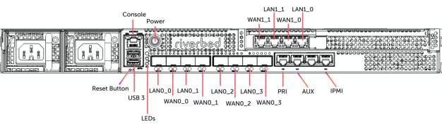
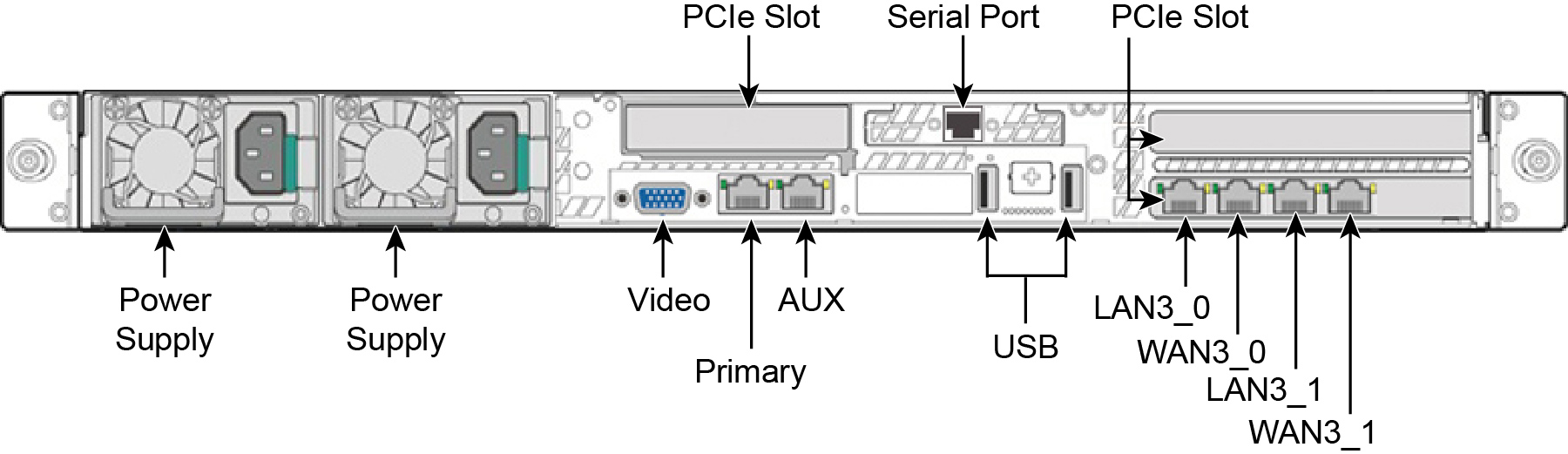
Model | CXA-04090 |
|---|---|
Form factor | BR-H (Branch-High) |
Form Factor | 1U |
CPU | Intel IceLake-D D1844NT (10C, 2.0 GHz) QAT 20 Gbps |
Memory | 32 GB DDR4 UDIMM (2x16 GB) 2666 MHz ECC |
Storage - Segstore | 2 x M.2 NVMe 80 mm 2 x 480 GB, Innodisk 4TS2-P |
Storage - Management | 2 x 2.5” SATA, 7 mm 960 GB, Innodisk 3TS9-P |
Boot Device | eMMC 32 GB |
Console | RJ45 |
Ethernet Ports (on-board) | 3 2.5GE : PRI/AUX/Unused 1 GE : BMC/IPMI 4 SFP+ : LAN/WAN (no bypass) 4 SFP : LAN/WAN (no bypass) |
Bypass Ports (default) | 4 GE (2 pairs) via add-on NIC |
PCIe Slot | 1 FH 3/4L (Gen4x16) |
USB 3.0 | 2 |
Power Supply | 2x Hot-swappable/Redundant, 500W (80+ Platinum) |
MTBF | TBD |
Model | CXA-04090 | |
|---|---|---|
AC input | 120v | 230v |
Max. watts | 156 | 153 |
Max. amps. | 1.30 | 1.28 |
Power factor | 0.98 | 0.99 |
Max. volt-ampere | 159 | 155 |
Typical watts | 124 | 122 |
BTU (typical) | 531 | 522 |
Model | CXA-04090 |
|---|---|
Temperature (operating) | 0-45°C (32-113°F) |
Temperature (storage) | -40-60°C (-40-140°F) |
Humidity (operating) | 10-90% (non-condensing) |
Humidity (storage) | 5-95% (non-condensing) |
Altitude (operating) | 9,800 feet |
Altitude (storage) | 39,000 feet |
Operating Acoustic Noise | <60 dBA |
Dimension (system) Excluding rack ears and handles | 430 x 330.2 x 43.8 mm 16.9 x 13.0 x 1.72" (W x D x H) |
Dimension (system) Including rack ears and handles | 482.4 x 359 x 43.8 mm 19.0 x 14.1 x 1.72" (W x D x H) |
Dimension (packaging) | 580 x 480 x 175 mm 22.8 x 18.9 x 6.9" (W x D x H) |
Weight (system) | 7.2 kg (15.9 lbs) |
Weight (packaged) | 9.8 kg (21.6 lbs) |
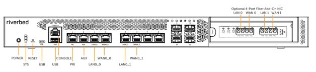
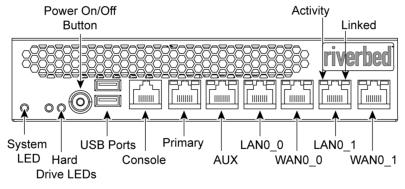
LED or button | Description |
|---|---|
Power On/Off Button and Integrated LED | On = Blue (System is turned on.) Sleep State = Yellow (System is in S5 sleep state.) Off = No light (Power is off.) |
System LEDs | The combination of LED 1 and LED 2 defines the system state: LED 1 = Yellow, LED 2 = Yellow, System State = Critical LED 1 = Yellow, LED 2 = Green, System State =Degraded LED 1 = Green, LED 2 = Green, System State = Healthy LED 3 - Not used; default is off LED 4 - Not used; default is off |
Reset Button | Press to restore factory defaults. |
Console port | RJ45 port |
USB Ports v3.0 | 1 - USB Type A port 1 - USB Type C port |
Port 1 PRI = Primary port | Left LED Link = Green Activity = Blinks green Right LED 10 Mbps data rate = No light (with link on left LED) 100 Mbps data rate = Green 1000 Mbps data rate = Yellow |
Port 2 AUX = Auxiliary port | Left LED Link = Green Activity = Blinks green Right LED 10 Mbps data rate = No light (with link on left LED) 100 Mbps data rate = Green 1000 Mbps data rate = Yellow |
Ports 3-6 LAN/WAN ports | Left LED Link = Green Activity = Blinks green Bypass/Disconnect = Yellow Right LED 10 Mbps data rate = No light (with link on left LED) 100 Mbps data rate = Green 1000 Mbps/1 Gbps = Yellow |
Ports 7-8 (on-board) | Not used. |
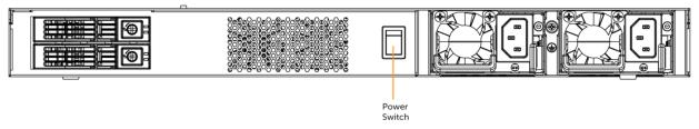
LED or button | Description |
|---|---|
HDDs | Activity LED (upper light) Activity = Blinks green (drive present, with activity. Status LED (lower light) Failed Disk = Solid amber |
Power Supply LEDs | Power on and healthy = Green Standby = 1 Hz blinks green Power off = Off Unplugged or power lost but second power supply has power = Amber (for about 5 seconds) then turns Off Power on with warning = 1 Hz blinks amber (Indicates high temperature, high power, high current, or slow fan.) |
Specification | 1U 3080 |
|---|---|
Form factor | 1U rack mountable unit |
RAM | 24 GB |
HDD | 2 x 1 TB |
SSD | 1 x 32 GB (for boot) |
Data store | 400 GB |
Dimensions (LxWxH) | 15.25 x 17.24 x 1.73 in (387.35 x 483 x 44 mm) |
Weight (without packaging) | 27 lb (12.25 kg) |
Power (Typical) | 70 W |
BTU | 242 |
Voltage | 100-240 V |
PSU | 2 x hot-swappable/redundant, 550W W = 100-240 VAC/7.1/3.4A, 47-63 Hz |
PCIe slots | 1 FHFL (full height/full length) |
Bypass ports/maximum no. | 4 (on-board)/8 (with add-on card) |
System | 1U 3080 | |
|---|---|---|
PSU type | 2 x 550 W | |
AC input | 120 V | 240 V |
Max. watts | 88.7 W | 73.8 W |
Max. amps. | 0.9144 A | 0.488 A |
Power factor | 98.58 W/VA | 95.6 W/VA |
Max. volt-ampere | 89.97 VA | 77.19 VA |
Typical watts | 70.96 W | 59.04 W |
BTU (typical) | 241.97 BTU | 201.32 BTU |
Specification | CX 3080 |
|---|---|
Operating acoustic | 45 dB (typical) |
Temperature (operating) | 32°F to 113°F (0°C to 45°C) |
Temperature (storage) | -40°F to 149°F (-40°C to 65°C) |
Relative humidity | 20% to 80%, noncondensing (Operating) 10% to 95%, noncondensing (Storage) |
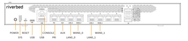
Front LEDs and buttons | Status |
|---|---|
Power Button LED | On = Blue (System is turned on.) Sleep State = Yellow (System is in a sleep state.) Off = No light (Power is off.) |
System LEDs | The combination of LED 1 and LED 2 defines the system state: LED 1 = Yellow, LED 2 = Yellow, System State = Critical LED 1 = Yellow, LED 2 = Green, System State =Degraded LED 1 = Green, LED 2 = Green, System State = Healthy LED 3 - Not used; default is off LED 4 - Not used; default is off |
Reset button | Restores system to factory defaults. |
Console port | RJ45 port |
USB ports v3.0 | 1 - USB Type A port 1 - USB Type C port |
Port 1 PRI | Left LED = Link/Bypass Link = On (Solid green) Activity =Blinks green Right LED= Speed 10 Mbps data rate = Off 100 Mbps data rate = Green 1000 Mbps data rate = Amber |
Port 2 AUX | Left LED = Link/Bypass Link = On (Solid green) Activity =Blinks green Right LED = Speed 10 Mbps data rate = Off 100 Mbps data rate = Green 1000 Mbps data rate = Amber |
Ports 3-6: LAN/WAN LEDs | Left LED Link = Green Activity = Blinks green Bypass/Disconnect = Yellow Right LED 10 Mbps data rate = No light (with link on left LED) 100 Mbps data rate = Green 1000 Mbps/1 Gbps = Yellow |
Ports 7-8 (on-board) | Not used. |
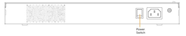
LED or button | Description |
|---|---|
Power Supply LEDs | Power on and healthy = Green Standby = 1 Hz blinks green Power off = Off Power lost but second power supply has power = Amber Power on with warning = 1 Hz blinks amber (indicates high temperature, high power, high current, or slow fan) |
Specification | 580 desktop | 780 desktop |
|---|---|---|
Power Watt (typical) | 37 W | 60 W |
BTU | 128 BTU | 205 BTU |
RAM | 16 GB | 16 GB |
HDD | 1 x 1 TB | 1 x 1 TB |
SSD | 1 x 32 GB (for boot) | 1 x 32 GB (for boot) |
Data store | 200 GB | 200 GB |
Dimensions (LxWxH) | 12.25 x 13.75 x 1.73 in. 311.15 x 349.25 x 44 mm | 12.25 x 13.75 x 1.73 in. 311.15 x 349.25 x 44 mm |
Weight (without packaging) | 6 lb (2.7 kg) | 6 lb (2.7 kg) |
Voltage frequency | 100-240 V/2.5 A 50/60 Hz | 100-240 V/2.5 A 50/60 Hz |
PSU | 1 x Internal, 200 W 100-240 VAC/2.5 A, 50/60 Hz | 1 x Internal, 200 W 100-240 VAC/2.5 A, 50/60 Hz |
Onboard bypass ports/max no. ports | 4 | 4 |
System | CX 780 | |
|---|---|---|
PSU type | 2 x 550 W | |
AC input | 120 V | 240 V |
Max. watts | 75.1 W | 60.7 W |
Max. amps. | 0.7692 A | 0.39 A |
Power factor | 99 W/VA | 95.2 W/VA |
Max. volt-ampere | 75.85 VA | 63.76 VA |
Typical watts | 60.08 W | 48.56 W |
BTU (typical) | 204.87 BTU | 165.58 BTU |
System | CX 580 | |
|---|---|---|
PSU type | 2 x 550 W | |
AC input | 120 V | 240 V |
Max. watts | 46.8 W | 33.2 W |
Max. amps. | 0.486 A | 0.22 A |
Power factor | 97.71 W/VA | 94.8 W/VA |
Max. volt-ampere | 47.89 VA | 35.02 VA |
Typical watts | 37.44 W | 26.56 W |
BTU (typical) | 127.67 BTU | 90.56 BTU |
Specification | CX580 desktop | CX780 desktop |
|---|---|---|
Operating acoustic | 45 dBA Sound pressure (Typical) | 45 dBA Sound pressure (Typical) |
Temperature (operating) | 0°C to 45°C 32°F to 113°F | 0°C to 45°C 32°F to 113°F |
Temperature (storage) | -40°C to 65°C -40°F to 149°F | -40°C to 65°C -40°F to 149°F |
Relative humidity | 20% to 80% noncondensing | 20% to 80% noncondensing |
Storage humidity | 5% to 95% noncondensing | 5% to 95% noncondensing |
Reference | LED or button | Description |
|---|---|---|
1 | System ID Button with Integrated LED | Maintenance = Blue Toggles the integrated ID LED and the blue server board ID LED on and off. The System ID LED identifies the system for maintenance when installed in a rack of similar server systems. You can also remotely turn on and turn off the System ID LED using the IPMI chassis-identify command, which causes the LED to blink for 15 seconds. A duplicate System ID LED is on the back of the appliance to the left of the video port. |
2 | NMI Button | Pressing the NMI button puts the appliance in a halt state and issues a non-maskable interrupt (NMI). This helps when performing diagnostics for a given issue where a memory download is necessary to determine the cause of the problem. To prevent an inadvertent system halt, the NMI button is located behind the Front Control Panel faceplate and is only accessible with the use of a small-tipped tool such as a pin or paper clip. |
3 10 | Network Activity LED Primary Auxiliary | Link = Green Activity = Blinks green. The blink rate is consistent with the amount of network activity. The appliance doesn’t use the LEDs 4 and 9 shown in Figure: Front panel desktop x80. |
5 | System Cold Reset Button | Pressing this button reboots the appliance. |
6 | System Status LED | The System Status LED shows the current health of the server system. Healthy = Green Degraded = Yellow Critical = Blinks yellow |
7 | Power Button with Integrated LED | System on = Green System off = No light |
8 | Drive Activity | Activity = Blinks green |
LEDs on Disk Drives | Activity LED Read/Write Activity = Blinks Green Disk Fault LED Failed Disk = Orange RAID Rebuild = Blinks orange | |
LEDs on Primary and AUX Ports | Left LED Link = Green Activity = Blinks green Right LED 10 MB/sec data rate = No light (with link on left LED) 100 MB/sec data rate = Green 1000 MB/sec data rate = Yellow | |
LEDs on Default Four-Port Copper Bypass Card | Link/Activity LED Link = Green Activity = Blinks green Speed/Bypass/Disconnect LED 1000 Mbit/s = Yellow 100 Mbit/s = Green 10 Mbit/s = Off Bypass = Blinks green Disconnect = Blinks yellow | |
LEDs on Power Supply | Power on and healthy = Green Power off = Off Standby = Blinks green Power lost but second power supply has power = Amber Power on with warning events (high temperature, high power, high current, slow fan) = Blinks amber |
CX5070 M/H | CX7070 L | CX7070 M | CX7070 H | |
|---|---|---|---|---|
Form factor | 2U | 2U | 2U | 2U |
Hard disk/SSD | 2 x 1000 GB HDD 6 x 160 GB SSDs | 2 x 1000 GB HDD 6 x 300 GB SSDs | 2 x 1000 GB HDD 8 x 300 GB SSD | 2 x 1000 GB HDD 16 x 300 GB SSD |
Data Store | 960 GB SSD | 1.8 TB SSD | 2.4 TB SSD | 4.8 TB SSD |
Dimensions (LxWxH) | 27.87 x 17.24 x 3.45 in. 707.8 x 438 x 87.6 mm | 27.87 x 17.24 x 3.45 in. 707.8 x 438 x 87.6 mm | 27.87 x 17.24 x 3.45 in. 707.8 x 438 x 87.6 mm | 27.87 x 17.24 x 3.45 in. 707.8 x 438 x 87.6 mm |
Weight (without packaging) | 41 lb/18.6 kg | 41 lb/18.6 kg | 41 lb/18.6 kg | 42 lb/19.05 kg |
Voltage frequency | 100-127 V, 200-240 V | 100-127 V, 200-240 V | 100-127 V, 200-240 V | 100-127 V, 200-240 V |
PSU | 2 x 770 W 100-127 VAC/8.2 A, 50/60 Hz 200-240 VAC/4.4 A, 50/60 Hz | 2 x 770 W 100-127 VAC/8.2 A, 50/60 Hz 200-240 VAC/4.4 A, 50/60 Hz | 2 x 770 W 100-127VAC/8.2A, 50/60 Hz 200-240VAC/4.4A, 50/60 Hz | 2 x 770 W 100-127 VAC/8.2 A, 50/60 Hz 200-240 VAC/4.4 A, 50/60 Hz |
PCI slots | 6 | 6 | 6 | 6 |
Included bypass ports/max no. ports | 4/20 | 4/20 | 4/20 | 4/20 |
System | CX5070 | CX7070 | ||
|---|---|---|---|---|
Configuration | All (M/H) | All (L/M/H) | ||
PSU type | 2 x 770W | 2 x 770W | ||
AC input | 120V | 230V | 120V | 230V |
Max. amps. | 3.0 | 1.5 | 5.3 | 2.7 |
Max. watts | 298 | 291 | 527 | 520 |
Typical watts | 238 | 232 | 422 | 416 |
Max VA | 301 | 293 | 533 | 524 |
Power factor | 98.96 | 99.16 | 98.96 | 99.16 |
BTU (typical) | 814 | 794 | 1439 | 1418 |
CX5070 | CX7070 | |
|---|---|---|
Operating acoustic | 7.0 BA sound power (Typical) 55 dBa sound pressure | 7.0 BA sound power (Typical) 55 dBa sound pressure |
Temperature (operating) | 10°C to 35°C 50°F to 95°F | 10°C to 35°C 50°F to 95°F |
Temperature (storage) | -40°C to 70°C -40°F to 158°F | -40°C to 70°C -40°F to 158°F |
Relative humidity | 50% to 90%, noncondensing with a maximum wet bulb of 28°C (at temperatures from 25°C to 35°C) | 50% to 90%, noncondensing with a maximum wet bulb of 28°C (at temperatures from 25°C to 35°C) |
Reference | LED or button | Description |
|---|---|---|
1 | System ID Button with Integrated LED | Maintenance = Blue Toggles the integrated ID LED and the blue server board ID LED on and off. The System ID LED identifies the system for maintenance when installed in a rack of similar server systems. You can also remotely turn on and turn off the System ID LED using the IPMI chassis-identify command, which causes the LED to blink for 15 seconds. A duplicate System ID LED is on the back of the appliance to the left of the video port. |
2 | NMI Button | Pressing the NMI button puts the appliance in a halt state and issues a non-maskable interrupt (NMI). This helps when performing diagnostics for a given issue where a memory download is necessary to determine the cause of the problem. To prevent an inadvertent system halt, the NMI button is located behind the Front Control Panel faceplate and is only accessible with the use of a small-tipped tool such as a pin or paper clip. |
3 10 | Network Activity LED Primary Auxiliary | Link = Green Activity = Blinks green. The blink rate is consistent with the amount of network activity. The appliance doesn’t use the LEDs 4 and 9 shown in Figure: Front panel desktop x80. |
5 | System Cold Reset Button | Pressing this button reboots the appliance. |
6 | System Status LED | The System Status LED shows the current health of the server system. Healthy = Green Degraded = Yellow Critical = Blinks yellow A duplicate System ID LED is on the back of the appliance to the right of the AUX port. |
7 | Power Button with Integrated LED | System on = Green System off = No light |
8 | Drive Activity | Activity = Blinks green |
LEDs on Disk Drives | Activity LED Read/Write Activity = Blinks green Disk Fault LED Failed disk = Orange RAID rebuild = Blinks orange | |
LEDs on Primary and AUX Ports | Left LED Link = Green Activity = Blinks Green Right LED 10 Mbps data rate = No light (with link on left LED) 100 Mbps data rate = Green 1000 Mbps data rate = Yellow | |
LEDs on Default Four-Port Copper Bypass Card | Link/Activity LED Link = Green Activity = Blinks green Speed/Bypass/Disconnect LED 1000 Mbps = Yellow 100 Mbps = Green 10 Mbps = Off Bypass = Blinks green Disconnect = Blinks yellow | |
LEDs on Power Supply | Power on and healthy = Green Power off = Off Standby = Blinks green Power lost but second power supply has power = Amber Power on with warning events (high temperature, high power, high current, slow fan) = Blinks amber |
CX3070 L/M/H | |
|---|---|
Form factor | 1U |
Hard disk | 2 x 1000 GB, 2 SSD x 160 |
Data store | 320 GB SSD |
Dimensions (LxWxH) | 25.21 x 17.24 x 1.7 in 640.4 x 438 x 43.2 mm |
Weight (without packaging) | 27 lb / 12.2 kg |
Voltage frequency | 100-127 V, 200-240 V |
PSU | 2 x 450 W 100-127 VAC/8 A, 50/60 Hz 200-240 VAC/4 A, 50/60 Hz |
PCI slots | 3 |
Included bypass ports/max no. ports | 4/12 |
System | CX3070 | CX3070 |
|---|---|---|
Configuration | All (L/M/H) | All (L/M/H) |
PSU type | 2 x 450 W | 2 x 450 W |
AC input | 120 V | 230 V |
Max. amps. | 1.54 | .76 |
Max. watts | 152.8 | 145.4 |
Typical watts | 122 | 116 |
Max VA | 154 | 147 |
Power factor | 98.96 | 99.16 |
BTU (typical) | 417 | 397 |
Specification | Description |
|---|---|
Operating acoustic | 7.0 BA sound power (Typical) 52 dBa sound pressure |
Temperature (operating) | 10°C to 35°C 50°F to 95°F |
Temperature (storage) | -40°C to 70°C -40°F to 158°F |
Relative humidity | 50% to 90% noncondensing with a maximum wet bulb of 28°C (at temperatures from 25°C to 35°C) |
LED | Status |
|---|---|
System | Healthy = Blue Degraded = Yellow Critical = Red Power off = None |
Power Button LED | System off = No light Standby mode = Yellow Power on = Blue |
Hard Drive LED | Activity = Blinks blue Failed disk = Orange |
Primary LED | Left LED Link = Green Activity = Blinks green Right LED GB = Yellow 100 MB = Green 10 MB = No light (with link on left LED) |
LAN/WAN LEDs | Left LED Link = Green Activity = Blinks green Bypass/Disconnect = Yellow Right LED GB = Yellow 100 MB = Green 10 MB = No light (with link on left LED) |
Specification | CX570 desktop L/M/H | CX770 desktop L/M/H |
|---|---|---|
Power (typical) | 45 W | 50 W |
VA (max) | 63.8 | 66.8 |
BTU | 145 BTU | 165 BTU |
Hard disk | 1 x 320 GB 2.5” HDD 1 x 80 GB SSD | 1 x 320 GB 2.5” HDD 1 x 160 GB SSD |
Data store | 70 GB SSD | 150 GB SSD |
Dimensions (LxWxH) | 13 x 8x 1.73 in. 330 x 204 x 44 mm | 13 x 8 x 1.73 in. 330 x 204 x 44 mm |
Weight (without packaging) | 5.5 lb 2.4 kg | 5.5 lb 2.4 kg |
Voltage frequency | 100-240 V 50-60 Hz | 100-240 V 50-60 Hz |
PSU | Single 84 W External 100-240 VAC, 50/60 Hz, 2-1 A | Single 84 W External 100-240 VAC, 50/60 Hz, 2-1 A |
Onboard bypass ports/max no. ports | 4 | 4 |
Specification | CX570 desktop L/M/H | CX770 desktop L/M/H |
|---|---|---|
Operating acoustic | 45 dBA Sound pressure (Typical) | 45 dBA Sound pressure (Typical) |
Temperature (operating) | 0°C to 45°C 32°F to 113°F | 0°C to 45°C 32°F to 113°F |
Temperature (storage) | -40°C to 65°C -40°C to 149°F | -40°C to 65°C -40°F to 149°F |
Relative humidity | 20% to 80% noncondensing | 20% to 80% noncondensing |
Storage humidity | 5% to 95% noncondensing | 5% to 95% noncondensing |