VLAN Segregation
This chapter discusses VLAN segregation. The driving factor of most use cases is to maintain separation of traffic between VRFs while leveraging the same physical hardware. You can use VLAN segregation when you deploy an Interceptor on a network that must be logically segregated to achieve traffic isolation, security, and diverse network policies. This chapter includes the following sections:
Enterprises, managed service providers (MSPs), or any company that requires traffic separation might also require optimization services to support the logically separated networks.
Overview of VLAN segregation
A logical network is sometimes referred to as a virtual routing and forward instance (VRF). Traffic for a VRF is identified and separated through the use of Layer-2 tags, such as 802.1q VLAN tags or MPLS labels. The Layer-2 tag and associated Layer-3 VRF mapping is applied to the configuration of the network devices. VLAN segregation enables IT organizations to provide traffic redirection and optimization by applying the same Layer-2 tag to Layer-3 tag VRF mapping on an Interceptor supporting large enterprises, MSPs, or multitenant environments, and any organization requiring separation of traffic for security.
Note: The terms logical network and VRF are used interchangeably in this chapter.
The key reasons that IT organizations use VRFs are the distinct Layer-3 routing table per VRF and the ability to reuse IP addresses between VRFs. From your data center, you can provide a VRF to partners, business units, or guests, while keeping traffic segregated and without installing additional network hardware for each VRF. For example, MSPs can host resources and segregate traffic between customers represented with different VRFs.
Prior to Interceptor 4.0, the Interceptor did not preserve the VLAN tag when redirecting to a local SteelHead. The Interceptor replaced the tag with the VLAN tag on the in-path interface, and the association between VLAN tag and VRF was lost. While there are workarounds for some traffic segregation scenarios, VLAN segregation provides broad support to more environments in which traffic segregation is critical.
VLAN transparency only ensures that optimized traffic is maintained within the VRF instance. If multiple VLANs exist within the same instance, optimized traffic from the SteelHead can traverse other VLANs within the instance depending on routing configurations.
For more information about VRF, see the SteelHead Deployment Guide.
This chapter uses the following terms and definitions:
• VRF - A separate routing and forwarding table within a network device. Traffic is associated to a VRF by a Layer-2 tag.
• Instances - A logical Interceptor appliance. An instance maps the VLAN tags to a logical Interceptor dedicated to a VRF.
• VLAN transparency - Maintains VLAN tag for pass-through and redirected traffic.
• Subinterface - A logical interface on a physical interface. A logical interface is usually denoted by a physical interface followed by a period (.), followed by a number. For example, inpath0_0.10 is the subinterface for VLAN 10 tagged traffic on the physical interface inpath0_0. The number refers to the 802.1Q VLAN tag.
• Instance configuration mode - A subconfiguration mode allowing instance-level configuration to be performed on a specific instance. This configuration mode is denoted by the (instance-config) # prompt.
VLAN use cases
There are three common use cases for VLAN segregation:
• Multitenancy
• Security requirements
• Overlapping IP address on clients and servers
Multitenancy is when tenants use a shared facility but are logically separated. Tenant traffic crosses the same network devices, but can access only their assigned services. VLAN segregation enables you to create logical Interceptors for the logical network for each tenant. Traffic segregation requirements are not affected. A given logical Interceptor can have traffic redirection rules assigned to best fit the requirements of the tenant. Traffic segregation is maintained because the SteelHead resources, either virtual or physical, are dedicated to each tenant.
You might have security requirements to maintain traffic segregation between logical networks. For example, you might want to separate traffic such as payment card information, personal identification information, and healthcare information. Similar to the multitenancy use case, you also want to dedicate optimization resources to each logical network. VLAN segregation enables SteelHeads that handle sensitive data to be dedicated to handling the data, and it enables traffic redirection policies tuned to the specific requirements for each logical network.
Overlapping IP addresses between logical networks is another common use case. Overlapping IP addresses can occur when two companies merge. For example:
• The companies create a VRF to represent the network of each company.
• The Interceptor with VLAN segregation uses 802.1q VLAN tags to identify traffic associated with each company VRF.
• The Interceptor maintains the VLAN tag and redirects the traffic to a local SteelHead cluster dedicated to that VRF.
Because you configure one Interceptor to be many logical appliances (one logical appliance per each VRF), the overlapping IP addresses are kept separated by the VRF and VLAN tag and redirected to the correct dedicated SteelHeads. Because the SteelHeads are dedicated for each cluster, the SteelHeads do not detect the overlap.
Overlapping IP addresses are not supported on Interceptors.
VLAN segregation Interceptor cluster virtualization
The VLAN segregation feature enables you to support a VRF with a logical Interceptor by creating an instance on the Interceptor and associating the instance with a single VLAN or group of VLANs. The VLANs are identified by an 802.1q VLAN tag. The Interceptor uses this tag to direct traffic to the assigned instance. Essentially, an instance is a label mapping a logical Interceptor to the VRF and associated VLANs. VLAN segregation considers only 802.1Q VLAN tags to identify traffic. The Interceptor does not use other methods (such as GRE, Q-in-Q, MPLS, VPNs, and so on) to associate traffic with an instance.
An instance contains the configuration for an optimization cluster of Interceptors and SteelHeads, but it is independent from other instances within the same Interceptor. Each instance has its own VLANs, in-path and load-balancing rules, and dedicated SteelHeads. An instance can be provisioned dynamically and can redirect traffic for more than one VLAN.
Figure: Logical networks using Interceptors and SteelHeads shows a data center supporting services for three VRFs. Each customer communicates over a WAN to an edge router using a VRF to maintain segregation. Traffic to servers on the back end is marked with an 802.1q VLAN tag, and the switch (Layer-2 or Layer-3) sends to only the servers assigned to the VRF. When the Interceptor and SteelHeads are added to the network, the Interceptor is configured with three instances. A subset of SteelHeads is dedicated to each instance and not shared between instances.
Figure: Logical networks using Interceptors and SteelHeads
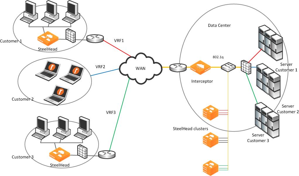
Physically, the optimization cluster appears to be one Interceptor and nine SteelHeads, but logically there are three Interceptors, each communicating with three SteelHeads, respectively. As traffic for any VRF enters the Interceptor, the mapping of VLAN tag to instance is used to determine the logical Interceptor and dedicated pool of local SteelHeads.
Pass-through and redirected traffic flowing across the Interceptor retains its VLAN tag. The SteelHead communicates with its remote peer, logical Interceptor, and local servers. In
Figure: Logical networks using Interceptors and SteelHeads, SteelHeads are dedicated for each customer, local at the data center and at the remote site.
If a remote-site SteelHead is supporting VLAN transparency and multiple VRFs, you might need additional configuration on the SteelHeads: for example, full transparency and out-of-band transparency.
Figure: Example two: logical networks using Interceptors and SteelHeads shows another representation of a physical optimization cluster and logical optimization cluster. The physical topology shows a quad Interceptor deployment with 12 SteelHeads. When you use VLAN segregation, the logical topology shows that the physical Interceptors are represented as an instance and assigned a group of VLANs, and the SteelHeads are dedicated to each instance.
Figure: Example two: logical networks using Interceptors and SteelHeads
Feature compatibility and limitations
VLAN segregation is compatible with many of the features from previous versions of the Interceptor. Compatible features include Xbridge, correct addressing, full transparency, asymmetric routing, connection forwarding, EtherChannels, clusters, and load balancing with fair peering v2 and round robin. However, VLAN segregation is not supported when you deploy the Interceptor virtually in-path with WCCP or PBR.
VLAN segregation does not support the legacy load-balancing algorithm fair peering v1 nor support communicating with cluster SteelHeads over a specific interface. The default setting for VLAN segregation is communicating with cluster SteelHeads using multiple interfaces and fair peering v2.
To maximize the benefits of VLAN segregation, consider the following recommendations and limitations:
• We recommend a maximum of 30 instances per Interceptor.
• Interceptor 4.0 and later supports a maximum of 200 VLAN interfaces (in-path interfaces x number of VLANs assigned to all instances).
Example: You have 20 instances with five VLANs assigned to each instance. If you deploy an Interceptor with one in-path interface, the total (number of in-path interfaces x VLANs) = 1 x 100 = 100. This deployment could support up to two in-path interfaces.
• We recommend that you use SteelHeads running RiOS 8.0.1 and later. SteelHeads running RiOS 6.5.6 to 8.0.1 might not be able to properly communicate with an Interceptor that has more than four physical in-path interfaces.
• Two instances cannot share the same set of VLANs or SteelHeads.
• Use unique IP addresses for all in-path interfaces in the physical optimization cluster across all instances, Interceptors, and SteelHeads:
– Interceptor in-path interfaces must have unique IP addresses across instances.
– SteelHead in-path interfaces must have unique IP addresses within the instance and across SteelHeads in other instances.
• We recommend that you use a maximum of 200 local SteelHeads across all instances, and that you do not have more than five VLAN tags per instance.
Deploying VLAN segregation
This section contains the following examples:
By default, the Interceptor 4.0 or later starts in standard mode, in which VLAN segregation is disabled. You enable VLAN segregation with the vlan-seg enable command, or from the Networking > Networking: VLAN Segregation page in the Interceptor Management Console.
After segregation is enabled, you must save your configuration and reboot the Interceptor. Because enabling VLAN segregation is disruptive, We recommend that you enable VLAN segregation during a maintenance window or prior to deployment on a production network.
VLAN segregation mode involves configuration that is global to all instances and there is configuration that is instance specific. Global configuration items are not affected by the conversion to VLAN segregation mode and apply to both modes.
The initial VLAN segregation configuration passes through all traffic on the Interceptor. Traffic is passed through even if there are existing IP addresses on an in-path interface, in-path rules, Interceptors or SteelHeads in a cluster, and load-balancing rules. When you move to VLAN segregation mode, you must configure each instance. All instance-specific configurations (in-path rules, load-balancing rules, cluster configuration, and so on) from standard mode are not applicable in VLAN segregation mode. Global configurations are applicable in both modes.
To apply rules from standard mode to an instance in VLAN segregation mode, we recommend that you make a copy of in-path and load-balancing rules so you can reapply these rules to the new instance.
Note: If you move back and forth between standard and VLAN segregation modes, the instance configurations remain in the VLAN segregation mode even though they are not visible in standard mode. However, we recommend that you apply the saved configurations to an unconfigured instance each time you move back into VLAN segregation mode.
The following configurations are global configurations:
• Xbridge
• Port labels
• In-path interface fail-to-bypass or fail-to-block
• Hardware-assisted pass-through rules
• Connection tracing
• Maximum Transmission Unit (MTU) sizing
The following configurations are instance-specific configurations:
• VLANs assigned and the subinterfaces created within the instance for each assigned VLAN
• Cluster Interceptors and SteelHeads
• In-path and load-balancing rules
• Enabling, disabling, and restarting an instance
When changing instance-specific MTU, the corresponding in-path interface global MTU automatically changes to be the highest MTU of any instance VLAN interface.
Note: If you configure the Interceptor using the CLI, you configure VLAN interface IP addresses and gateways in global mode.
To enable traffic redirection, you must create and define an instance and assign VLANs to that instance. This process creates a series of subinterfaces representing each VLAN in the instance on every physical in-path interface. For example, enabling an instance named Riverbed and assigning VLANs 100 and 200 creates a subinterface for all available in-path on the Interceptor such as inpath0_0.100/inpath0_1.100/inpath1_0.100/inpath1_1.100 and inpath0_0.200 /inpath0_1.200 /inpath1_0.200/inpath1_1.200. This action is the same for any other in-path interface on the Interceptor.
The following steps describe the VLAN segregation configuration workflow:
1. Enable VLAN segregation.
2. Save configuration.
3. Reboot Interceptor.
4. Per-instance:
• Create and edit instances.
• Assign VLANs for each instance.
• Configure the in-path interfaces for each VLAN, IP address, subnet mask, and gateway.
• Define the Interceptor cluster (this can be single Interceptor or serial, parallel or quad cluster).
• Define the SteelHead cluster.
• Adjust in-path and load-balancing rules (optional).
• Enable the instance.
Single Interceptor in VLAN segregation mode
The following example shows how to deploy a single Interceptor at a data center that supports three different logical networks. Each VRF is identified with two 802.1q VLAN tags that are already configured on the WAN edge router and LAN core router.
Figure: Example single Interceptor in VLAN segregation mode
Note: The 802.1q standard defines a native VLAN that is untagged. An untagged VLAN is assigned to an instance as a tagged VLAN.
1. Connect to Interceptor 1 CLI.
2. Configure VLAN segregation mode:
vlan-seg enable
write memory
reload
3. Create instances and assign VLANs:
instance-config create customerA
instance-config create customerB
instance-config create customerC
instance customerA
vlan 10 add
vlan 11 add
exit
instance customerB
vlan 20 add
vlan 21 add
exit
instance customerC
vlan 30 add
vlan 31 add
exit
4. Configure the IP addresses, default gateway, and routes for in-path subinterfaces:
Note: In the Interceptor Management Console, you configure the IP address assignment in instance configuration mode. The CLI commands are entered outside of instance configuration mode.
interface inpath0_0.10 ip address 172.16.10.112 /24
interface inpath0_0.11 ip address 172.16.11.112 /24
ip in-path-gateway inpath0_0.10 "172.16.10.1"
ip in-path-gateway inpath0_0.11 "172.16.11.1"
ip in-path route inpath0_0.10 172.16.110.0 /24 172.16.10.253
ip in-path route inpath0_0.11 172.16.110.0 /24 172.16.11.253
interface inpath0_0.20 ip address 172.16.20.112 /24
interface inpath0_0.21 ip address 172.16.21.112 /24
ip in-path-gateway inpath0_0.20 "172.16.20.1"
ip in-path-gateway inpath0_0.21 "172.16.21.1"
ip in-path route inpath0_0.20 172.16.120.0 /24 172.16.20.253
ip in-path route inpath0_0.21 172.16.120.0 /24 172.16.21.253
interface inpath0_0.30 ip address 172.16.30.112 /24
interface inpath0_0.31 ip address 172.16.31.112 /24
ip in-path-gateway inpath0_0.30 "172.16.30.1"
ip in-path-gateway inpath0_0.31 "172.16.31.1"
ip in-path route inpath0_0.30 172.16.130.0 /24 172.16.30.253
ip in-path route inpath0_0.31 172.16.130.0 /24 172.16.31.253
5. Assign SteelHeads to each instance optimization cluster:
instance customerA
steelhead name steelhead1 main-ip 172.16.110.100
steelhead name steelhead2 main-ip 172.16.110.101
steelhead name steelhead3 main-ip 172.16.110.102
exit
instance customerB
steelhead name steelhead4 main-ip 172.16.120.100
steelhead name steelhead5 main-ip 172.16.120.101
steelhead name steelhead6 main-ip 172.16.120.102
exit
instance customerC
steelhead name steelhead7 main-ip 172.16.130.100
steelhead name steelhead8 main-ip 172.16.130.101
steelhead name steelhead9 main-ip 172.16.130.102
exit
6. Make sure that the physical in-path interface is enabled, and restart each instance to begin optimization:
in-path interface inpath0_0 enable
instance customerA
restart
exit
instance customerB
restart
exit
instance customerC
restart
exit
Because each SteelHead is dedicated to an instance, you configure it the same as if the Interceptor is in standard mode. In the example in
Figure: Example single Interceptor in VLAN segregation mode, SteelHeads 1-3 are dedicated to instance customerA, SteelHeads 4-6 are dedicated to instance customerB, and SteelHeads 7-9 are dedicated to instance customerC.
To configure the SteelHeads
1. Connect to SteelHead 1 and enter the following commands:
interface inpath0_0 ip address 172.16.110.100 /24
ip in-path-gateway inpath0_0 172.16.110.1
in-path enable
in-path oop enable
steelhead communication enable
steelhead communication multi-interface enable
steelhead name interceptor1 main-ip 172.16.10.112
steelhead name interceptor1 additional-ip 172.16.11.112
2. Connect to SteelHead 2 and enter the following commands:
interface inpath0_0 ip address 172.16.110.101 /24
ip in-path-gateway inpath0_0 172.16.110.1
in-path enable
in-path oop enable
steelhead communication enable
steelhead communication multi-interface enable
steelhead name interceptor1 main-ip 172.16.10.112
steelhead name interceptor1 additional-ip 172.16.11.112
3. Connect to SteelHead 3 and enter the following commands:
interface inpath0_0 ip address 172.16.110.102 /24
ip in-path-gateway inpath0_0 172.16.110.1
in-path enable
in-path oop enable
steelhead communication enable
steelhead communication multi-interface enable
steelhead name interceptor1 main-ip 172.16.10.112
steelhead name interceptor1 additional-ip 172.16.11.112
4. Connect to SteelHead 4 and enter the following commands:
interface inpath0_0 ip address 172.16.120.100 /24
ip in-path-gateway inpath0_0 172.16.120.1
in-path enable
in-path oop enable
steelhead communication enable
steelhead communication multi-interface enable
steelhead name interceptor1 main-ip 172.16.20.112
steelhead name interceptor1 additional-ip 172.16.21.112
5. Connect to SteelHead 5 and enter the following commands:
interface inpath0_0 ip address 172.16.120.101 /24
ip in-path-gateway inpath0_0 172.16.120.1
in-path enable
in-path oop enable
steelhead communication enable
steelhead communication multi-interface enable
steelhead name interceptor1 main-ip 172.16.20.112
steelhead name interceptor1 additional-ip 172.16.21.112
6. Connect to SteelHead 6 and enter the following commands:
interface inpath0_0 ip address 172.16.120.102 /24
ip in-path-gateway inpath0_0 172.16.120.1
in-path enable
in-path oop enable
steelhead communication enable
steelhead communication multi-interface enable
steelhead name interceptor1 main-ip 172.16.20.112
steelhead name interceptor1 additional-ip 172.16.21.112
7. Connect to SteelHead 7 and enter the following commands:
interface inpath0_0 ip address 172.16.130.100 /24
ip in-path-gateway inpath0_0 172.16.130.1
in-path enable
in-path oop enable
steelhead communication enable
steelhead communication multi-interface enable
steelhead name interceptor1 main-ip 172.16.30.112
steelhead name interceptor1 additional-ip 172.16.31.112
8. Connect to SteelHead 8 and enter the following commands:
interface inpath0_0 ip address 172.16.130.101 /24
ip in-path-gateway inpath0_0 172.16.130.1
in-path enable
in-path oop enable
steelhead communication enable
steelhead communication multi-interface enable
steelhead name interceptor1 main-ip 172.16.30.112
steelhead name interceptor1 additional-ip 172.16.31.112
9. Connect to SteelHead 9 and enter the following commands:
interface inpath0_0 ip address 172.16.130.102 /24
ip in-path-gateway inpath0_0 172.16.130.1
in-path enable
in-path oop enable
steelhead communication enable
steelhead communication multi-interface enable
steelhead name interceptor1 main-ip 172.16.30.112
steelhead name interceptor1 additional-ip 172.16.31.112
You configure traffic redirection separately for each instance. The CLI commands that follow show an example configuration of a load-balancing rule for the instance named customerA. This load-balancing rule only affects traffic redirection for the VLANs associated with instance customerA. The same rules apply to load balancing within an instance in VLAN segregation mode as it does for standard mode. The following load-balancing rule redirects all port 80 traffic to SteelHead 3 only for instance customerA.
instance customerA
load balance rule redirect addrs 172.16.110.102 src all dest all dest-port 80
Interceptor cluster in VLAN segregation mode
We strongly recommend that you configure each instance as the same cluster type. For example, if one instance uses a quad deployment, then all instances should use a quad deployment. Configuring the same cluster types is helpful from a troubleshooting perspective and some pertinent global configurations, such as fail-to-block, affects all instances. For example, if you configure an in-path interface for fail-to-block, the physical in-path interface fails to block, affecting all instances. You cannot configure an in-path interface for fail-to-wire for one instance and fail-to-block for another.
For more details on cluster modes, see
Interceptor Clusters.
Figure: Interceptor parallel with fail-to-block deployment shows a parallel cluster. Building on the example in
Figure 6‑3, this example shows an additional WAN edge router and core switch. The WAN edge router and core switch are connected in a full mesh, and a parallel Interceptor is deployed. No matter what cluster-type you select, follow the best practices for that cluster type. We recommend that you configure all instance types as the same type of cluster.
Figure: Interceptor parallel with fail-to-block deployment
1. Connect to Interceptor 1 CLI.
2. Configure VLAN segregation mode:
vlan-seg enable
write memory
reload
3. Create instances and assign VLANs:
instance-config create customerA
instance-config create customerB
instance-config create customerC
instance customerA
vlan 10 add
vlan 11 add
vlan 12 add
vlan 13 add
exit
instance customerB
vlan 20 add
vlan 21 add
vlan 22 add
vlan 23 add
exit
instance customerC
vlan 30 add
vlan 31 add
vlan 32 add
vlan 33 add
exit
4. Configure the IP addresses, default gateway, and routes for in-path subinterfaces:
Note: In the Interceptor Management Console, you configure the IP address assignment in instance configuration mode. The CLI commands are entered outside of instance configuration mode.
interface inpath0_0.10 ip address 172.16.10.112 /24
interface inpath0_0.20 ip address 172.16.20.112 /24
interface inpath0_0.30 ip address 172.16.30.112 /24
interface inpath0_1.11 ip address 172.16.11.112 /24
interface inpath0_1.21 ip address 172.16.21.112 /24
interface inpath0_1.31 ip address 172.16.31.112 /24
ip in-path-gateway inpath0_0.10 "172.16.10.1"
ip in-path-gateway inpath0_0.20 "172.16.20.1"
ip in-path-gateway inpath0_0.30 "172.16.30.1"
ip in-path-gateway inpath0_1.11 "172.16.1.1"
ip in-path-gateway inpath0_1.21 "172.16.21.1"
ip in-path-gateway inpath0_1.31 "172.16.31.1"
ip in-path route inpath0_0.10 172.16.110.0 /24 172.16.10.253
ip in-path route inpath0_0.10 172.16.111.0 /24 172.16.10.253
ip in-path route inpath0_0.20 172.16.120.0 /24 172.16.20.253
ip in-path route inpath0_0.20 172.16.121.0 /24 172.16.20.253
ip in-path route inpath0_0.30 172.16.130.0 /24 172.16.30.253
ip in-path route inpath0_0.30 172.16.131.0 /24 172.16.30.253
ip in-path route inpath0_1.11 172.16.110.0 /24 172.16.11.253
ip in-path route inpath0_1.11 172.16.111.0 /24 172.16.11.253
ip in-path route inpath0_1.21 172.16.120.0 /24 172.16.21.253
ip in-path route inpath0_1.21 172.16.121.0 /24 172.16.21.253
ip in-path route inpath0_1.31 172.16.130.0 /24 172.16.31.253
ip in-path route inpath0_1.31 172.16.131.0 /24 172.16.31.253
5. Configure peer Interceptor and SteelHeads for each instance:
instance customerA
interceptor communication allow-failure enable
interceptor name interceptor2 main-ip 172.16.12.112
interceptor name interceptor2 additional-ip 172.16.13.112
steelhead name steelhead1 main-ip 172.16.110.100
steelhead name steelhead1 additional-ip 172.16.111.100
steelhead name steelhead2 main-ip 172.16.110.101
steelhead name steelhead2 additional-ip 172.16.111.101
steelhead name steelhead3 main-ip 172.16.110.102
steelhead name steelhead3 additional-ip 172.16.111.102
exit
instance customerB
interceptor communication allow-failure enable
interceptor name interceptor2 main-ip 172.16.22.112
interceptor name interceptor2 additional-ip 172.16.23.112
steelhead name steelhead4 main-ip 172.16.120.100
steelhead name steelhead4 additional-ip 172.16.121.100
steelhead name steelhead5 main-ip 172.16.120.101
steelhead name steelhead5 additional-ip 172.16.121.101
steelhead name steelhead6 main-ip 172.16.120.102
steelhead name steelhead6 additional-ip 172.16.121.102
exit
instance customerC
interceptor communication allow-failure enable
interceptor name interceptor2 main-ip 172.16.32.112
interceptor name interceptor2 additional-ip 172.16.33.112
steelhead name steelhead7 main-ip 172.16.130.100
steelhead name steelhead7 additional-ip 172.16.131.100
steelhead name steelhead8 main-ip 172.16.130.101
steelhead name steelhead8 additional-ip 172.16.131.101
steelhead name steelhead9 main-ip 172.16.130.102
steelhead name steelhead9 additional-ip 172.16.131.102
exit
6. Configure fail-to-block (you configure allow-failure under instance configuration mode done in the previous step):
no interface inpath0_0 fail-to-bypass enable
no interface inpath0_1 fail-to-bypass enable
7. Make sure the physical in-path interfaces are enabled, and restart instances to begin optimization:
in-path interface inpath0_0 enable
in-path interface inpath0_1 enable
service restart
instance customerA
restart
exit
instance customerB
restart
exit
instance customerC
restart
exit
8. Connect to Interceptor 2 CLI.
9. Configure VLAN segregation mode:
vlan-seg enable
write memory
reload
10. Create instances and assign VLANs:
instance-config create customerA
instance-config create customerB
instance-config create customerC
instance customerA
vlan 10 add
vlan 11 add
vlan 12 add
vlan 13 add
exit
instance customerB
vlan 20 add
vlan 21 add
vlan 22 add
vlan 23 add
exit
instance customerC
vlan 30 add
vlan 31 add
vlan 32 add
vlan 33 add
exit
11. Assign IP addresses, default gateway, and routes for subinterfaces:
interface inpath0_0.12 ip address 172.16.12.112 /24
interface inpath0_0.22 ip address 172.16.22.112 /24
interface inpath0_0.32 ip address 172.16.32.112 /24
interface inpath0_1.13 ip address 172.16.13.112 /24
interface inpath0_1.23 ip address 172.16.23.112 /24
interface inpath0_1.33 ip address 172.16.33.112 /24
ip in-path-gateway inpath0_0.12 "172.16.12.1"
ip in-path-gateway inpath0_0.22 "172.16.22.1"
ip in-path-gateway inpath0_0.32 "172.16.32.1"
ip in-path-gateway inpath0_1.13 "172.16.13.1"
ip in-path-gateway inpath0_1.23 "172.16.23.1"
ip in-path-gateway inpath0_1.33 "172.16.33.1"
ip in-path route inpath0_0.12 172.16.110.0 /24 172.16.12.253
ip in-path route inpath0_0.12 172.16.111.0 /24 172.16.12.253
ip in-path route inpath0_0.22 172.16.120.0 /24 172.16.22.253
ip in-path route inpath0_0.22 172.16.121.0 /24 172.16.22.253
ip in-path route inpath0_0.32 172.16.130.0 /24 172.16.32.253
ip in-path route inpath0_0.32 172.16.131.0 /24 172.16.32.253
ip in-path route inpath0_1.13 172.16.110.0 /24 172.16.13.253
ip in-path route inpath0_1.13 172.16.111.0 /24 172.16.13.253
ip in-path route inpath0_1.23 172.16.120.0 /24 172.16.23.253
ip in-path route inpath0_1.23 172.16.121.0 /24 172.16.23.253
ip in-path route inpath0_1.33 172.16.130.0 /24 172.16.33.253
ip in-path route inpath0_1.33 172.16.131.0 /24 172.16.33.253
12. Configure peer Interceptors and SteelHeads for each instance:
instance customerA
interceptor communication allow-failure enable
interceptor name interceptor1 main-ip 172.16.10.112
interceptor name interceptor1 additional-ip 172.16.11.112
steelhead name steelhead1 main-ip 172.16.110.100
steelhead name steelhead1 additional-ip 172.16.111.100
steelhead name steelhead2 main-ip 172.16.110.101
steelhead name steelhead2 additional-ip 172.16.111.101
steelhead name steelhead3 main-ip 172.16.110.102
steelhead name steelhead3 additional-ip 172.16.111.102
exit
instance customerB
interceptor communication allow-failure enable
interceptor name interceptor1 main-ip 172.16.20.112
interceptor name interceptor1 additional-ip 172.16.21.112
steelhead name steelhead4 main-ip 172.16.120.100
steelhead name steelhead4 additional-ip 172.16.121.100
steelhead name steelhead5 main-ip 172.16.120.101
steelhead name steelhead5 additional-ip 172.16.121.101
steelhead name steelhead6 main-ip 172.16.120.102
steelhead name steelhead6 additional-ip 172.16.121.102
exit
instance customerC
interceptor communication allow-failure enable
interceptor name interceptor1 main-ip 172.16.30.112
interceptor name interceptor1 additional-ip 172.16.31.112
steelhead name steelhead7 main-ip 172.16.130.100
steelhead name steelhead7 additional-ip 172.16.131.100
steelhead name steelhead8 main-ip 172.16.130.101
steelhead name steelhead8 additional-ip 172.16.131.101
steelhead name steelhead9 main-ip 172.16.130.102
steelhead name steelhead9 additional-ip 172.16.131.102
exit
13. Configure fail-to-block (you configure allow-failure under instance configuration mode done in the previous step):
no interface inpath0_0 fail-to-bypass enable
no interface inpath0_1 fail-to-bypass enable
14. Make sure the physical interface is enabled, and restart instances to begin optimization:
in-path interface inpath0_0 enable
in-path interface inpath0_1 enable
service restart
instance customerA
restart
exit
instance customerB
restart
exit
instance customerC
restart
exit
Because each SteelHead is dedicated to an instance, you configure it the same as when the Interceptor is in standard mode. SteelHeads 1-3 are dedicated to instance customerA, SteelHeads 4-6 are dedicated to instance customerB, and SteelHeads 7-9 are dedicated to instance customerC.
To configure the SteelHeads
1. Connect to SteelHead 1 and enter the following commands:
interface inpath0_0 ip address 172.16.110.100 /24
interface inpath0_1 ip address 172.16.111.100 /24
ip in-path-gateway inpath0_0 172.16.110.1
ip in-path-gateway inpath0_1 172.16.111.1
in-path enable
in-path oop enable
steelhead communication enable
steelhead communication multi-interface enable
steelhead name interceptor1 main-ip 172.16.10.112
steelhead name interceptor1 additional-ip 172.16.11.112
steelhead name interceptor2 main-ip 172.16.12.112
steelhead name interceptor1 additional-ip 172.16.13.112
2. Connect to SteelHead 2 and enter the following commands:
interface inpath0_0 ip address 172.16.110.101 /24
interface inpath0_1 ip address 172.16.111.101 /24
ip in-path-gateway inpath0_0 172.16.110.1
ip in-path-gateway inpath0_1 172.16.111.1
in-path enable
in-path oop enable
steelhead communication enable
steelhead communication multi-interface enable
steelhead name interceptor1 main-ip 172.16.10.112
steelhead name interceptor1 additional-ip 172.16.11.112
steelhead name interceptor2 main-ip 172.16.12.112
steelhead name interceptor2 additional-ip 172.16.13.112
3. Connect to SteelHead 3 and enter the following commands:
interface inpath0_0 ip address 172.16.110.102 /24
interface inpath0_1 ip address 172.16.111.102 /24
ip in-path-gateway inpath0_0 172.16.110.1
ip in-path-gateway inpath0_1 172.16.111.1
in-path enable
in-path oop enable
steelhead communication enable
steelhead communication multi-interface enable
steelhead name interceptor1 main-ip 172.16.10.112
steelhead name interceptor1 additional-ip 172.16.11.112
steelhead name interceptor2 main-ip 172.16.12.112
steelhead name interceptor2 additional-ip 172.16.13.112
4. Connect to SteelHead 4 and enter the following commands:
interface inpath0_0 ip address 172.16.120.100 /24
interface inpath0_1 ip address 172.16.121.100 /24
ip in-path-gateway inpath0_0 172.16.120.1
ip in-path-gateway inpath0_1 172.16.121.1
in-path enable
in-path oop enable
steelhead communication enable
steelhead communication multi-interface enable
steelhead name interceptor1 main-ip 172.16.20.112
steelhead name interceptor1 additional-ip 172.16.21.112
steelhead name interceptor2 main-ip 172.16.22.112
steelhead name interceptor2 additional-ip 172.16.23.112
5. Connect to SteelHead 5 and enter the following commands:
interface inpath0_0 ip address 172.16.120.101 /24
interface inpath0_1 ip address 172.16.121.101 /24
ip in-path-gateway inpath0_0 172.16.120.1
ip in-path-gateway inpath0_1 172.16.121.1
in-path enable
in-path oop enable
steelhead communication enable
steelhead communication multi-interface enable
steelhead name interceptor1 main-ip 172.16.20.112
steelhead name interceptor1 additional-ip 172.16.21.112
steelhead name interceptor2 main-ip 172.16.22.112
steelhead name interceptor2 additional-ip 172.16.23.112
6. Connect to SteelHead 6 and enter the following commands:
interface inpath0_0 ip address 172.16.120.102 /24
interface inpath0_1 ip address 172.16.121.102 /24
ip in-path-gateway inpath0_0 172.16.120.1
ip in-path-gateway inpath0_1 172.16.121.1
in-path enable
in-path oop enable
steelhead communication enable
steelhead communication multi-interface enable
steelhead name interceptor1 main-ip 172.16.20.112
steelhead name interceptor1 additional-ip 172.16.21.112
steelhead name interceptor2 main-ip 172.16.22.112
steelhead name interceptor2 additional-ip 172.16.23.112
7. Connect to SteelHead 7 and enter the following commands:
interface inpath0_0 ip address 172.16.130.100 /24
interface inpath0_1 ip address 172.16.131.100 /24
ip in-path-gateway inpath0_0 172.16.130.1
ip in-path-gateway inpath0_1 172.16.131.1
in-path enable
in-path oop enable
steelhead communication enable
steelhead communication multi-interface enable
steelhead name interceptor1 main-ip 172.16.30.112
steelhead name interceptor1 additional-ip 172.16.31.112
steelhead name interceptor2 main-ip 172.16.32.112
steelhead name interceptor2 additional-ip 172.16.33.112
8. Connect to SteelHead 8 and enter the following commands:
interface inpath0_0 ip address 172.16.130.101 /24
interface inpath0_1 ip address 172.16.131.101 /24
ip in-path-gateway inpath0_0 172.16.130.1
ip in-path-gateway inpath0_1 172.16.131.1
in-path enable
in-path oop enable
steelhead communication enable
steelhead communication multi-interface enable
steelhead name interceptor1 main-ip 172.16.30.112
steelhead name interceptor1 additional-ip 172.16.31.112
steelhead name interceptor2 main-ip 172.16.32.112
steelhead name interceptor2 additional-ip 172.16.33.112
9. Connect to SteelHead 9 and enter the following commands:
interface inpath0_0 ip address 172.16.130.102 /24
interface inpath0_1 ip address 172.16.131.102 /24
ip in-path-gateway inpath0_0 172.16.130.1
ip in-path-gateway inpath0_1 172.16.131.1
in-path enable
in-path oop enable
steelhead communication enable
steelhead communication multi-interface enable
steelhead name interceptor1 main-ip 172.16.30.112
steelhead name interceptor1 additional-ip 172.16.31.112
steelhead name interceptor2 main-ip 172.16.32.112
steelhead name interceptor2 additional-ip 172.16.33.112