Replacing SteelHead xx50 Components
This chapter describes how to replace components in SteelHead xx50 (including Interceptor 9350) appliances. It includes the following sections:
To access instructional videos describing how to identify specific SteelHead appliances as well as how to replace disk drives for each appliance family, go to
https://support.riverbed.com/kb/multimedia.htm.
Note: You must use approved components for the system to function properly. Installation of unapproved components will result in boot failure. To order components, contact Riverbed Support at
https://support.riverbed.com.
Required tools
You need the following tools and equipment to replace appliance components:
• You must use approved components for the appliance to function properly. Installation of unapproved components will result in boot failure. To order components, contact Riverbed Support at
https://support.riverbed.com.
• An antistatic strap. When you replace components, you must wear a grounded ESD antistatic strap to protect the hardware against electrostatic discharge. Make sure that the strap makes skin contact prior to handling equipment. For details, see
Electrostatic discharge guidelines.
• Use the magnetic Phillips screwdriver enclosed with your shipment to remove screws in the appliance. The magnetic screwdriver ensures screws are not lost in the appliance.
Replacing disk drives
The following sections describe how to replace disk drives in the xx50 appliances.
Note: When you replace the disk drive, you must wear a grounded ESD antistatic strap to protect the hardware against electrostatic discharge. Make sure that the strap makes skin contact prior to handling equipment.
If you have older hardware (for example, xx20 appliances), see the documentation set for RiOS 6.5.x or earlier. To service appliance 50, 100, 200, and 300 disk drives, contact Riverbed Support at
https://support.riverbed.com.
Replacing disk drives in SteelHead 150, 250, and 550 appliances
SteelHead 150, 250, and 550 appliances are equipped with a replaceable disk drive. The disk drive is not hot swappable; you must first turn off the system and remove the power cord before you replace the disk drives.
You must use approved disk drives. To order disk drives, contact your sales representative.
Caution: 
SteelHead 150, 250, and 550 disk drives are not hot swappable. You must turn off the system and remove the power cable before you replace the disk drive.
Caution: When removing or replacing disk drives, be careful not to touch the adjacent power supply unit. Touching the power supply unit can cause electric shock.
Caution: Use caution when you remove or replace components; they can become hot to the touch.
To replace the disk drive
1. Power down the SteelHead.
2. Unplug the power cord from the AC circuit.
3. Remove the SteelHead from its mounting rack, if necessary.
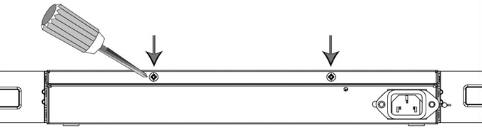
4. Remove the two locking screws on the back of the chassis.
Figure: Removing the locking screws
5. Position your thumbs on the top of the appliance and slide the cover back from the chassis.
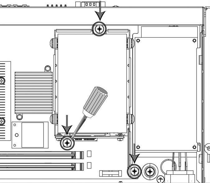
6. To remove the disk drive, unscrew the three screws and washers holding the disk drive casing to the chassis.
Caution: Use the magnetic screw driver that ships with the disk drive to remove the screws. Use caution when removing the screws and washers; do not drop them into the appliance.
Figure: Removing disk drive screws
7. Remove the old disk drive with casing from the appliance.
8. Insert the new disk drive with casing in the same position and secure the casing with the three included screws.
9. Replace the appliance cover, making sure the tabs of the cover are under the front frame.
10. Plug the power cord into the AC circuit.
11. Power on the appliance.
The new disk drive runs through a self-test automatically. You do not need to set up or configure the new disk drive.
Replacing disk drives in the Interceptor 9350
Interceptor 9350 appliances are equipped with replaceable, hot-swappable disk drives.
Note: Upgrading appliances can impact the data store. For detailed information about the impact of upgrading your system on the data store and RSP, see
Platform requirements.
You must use approved disk drives. To order disk drives, contact your sales representative.
Note: When you replace disk drives, you must wear a grounded ESD antistatic strap to protect the hardware against electrostatic discharge. Make sure that the strap makes skin contact prior to handling equipment.
Caution: Use caution when you remove or replace components; they can become hot to the touch.
To replace the disk drive
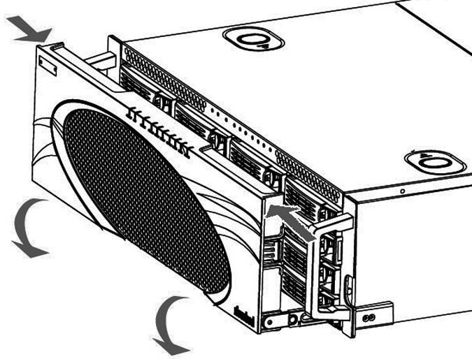
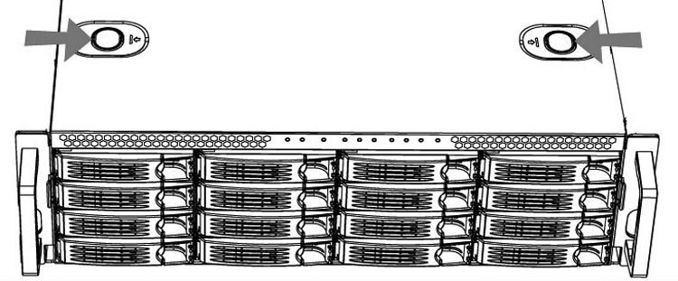
1. Open the bezel.
Press the buttons on each side of the bezel and pull toward you.
The bezel remains attached to the appliance on hinges.
Figure: Opening the bezel on the SteelHead
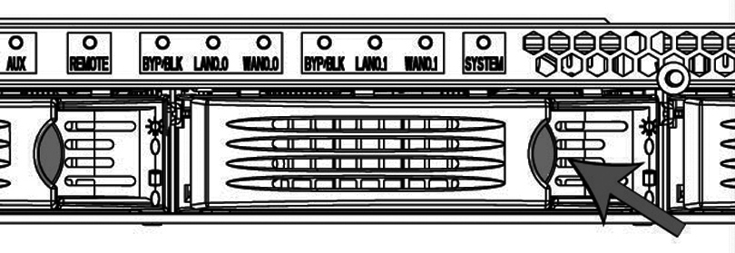
2. Identify the faulty disk drive.
The Alarm Status page in the Management Console identifies the faulty disk drive.
The drives are numbered in ascending order from left to right (that is, 0, 1, 2, 3). On Interceptor 9350 appliances, the bottom LED light indicates which drive to remove.
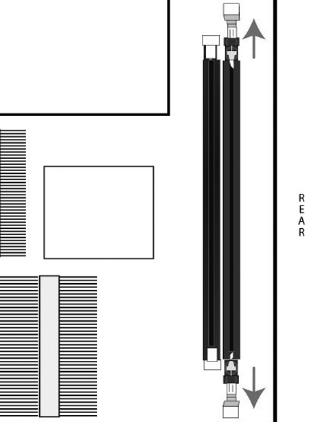
Figure: Disk drive numbers
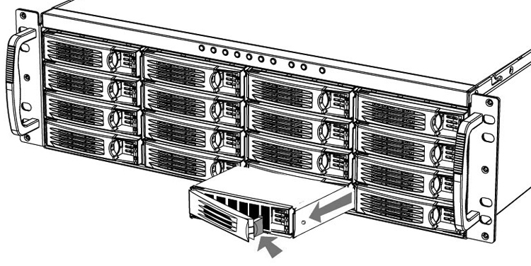
3. Press the orange release button to the left and pull the drive handle toward you to release the disk drive.
4. Slide the faulty disk drive out of the slot.
Make sure you remove the correct drive.
Figure: Removing and replacing the disk drives
5. Open the new disk-drive handle by pressing the orange release button.
6. Slide in the new disk drive until it mates with the back connectors in the chassis.
7. Press in the disk-drive handle to close.
The new disk drive runs through a self-test automatically. The disk drive automatically begins proper operation with the other disk drives. You do not need to set up or configure the new disk drive.
It takes approximately 3 to 4 hours, depending on the system load, to rebuild a new disk drive. The administrator user receives email when the disk drive has finished rebuilding.
Replacing power supply units
This section describes how to add or replace power supply units for the xx50 appliances. This section includes the following procedures:
Replacing power supply units in Interceptor 9350 appliances
Interceptor 9350 appliances are equipped with replaceable, hot-swappable power supply units.
Note: You must use approved power supply units. To order power supply units, contact your sales representative.
Caution: Use gloves when replacing the power supply units; they can become hot to the touch.
To replace a power supply unit
1. Locate the defective power supply unit and remove the power cord.
Power Supply 0 (PS0) is on the bottom, and Power Supply 1 (PS1) is on the top.
2. Press the green release tab toward the black handle, and pull the power supply unit out of the chassis.
Figure: Pulling out the power supply unit
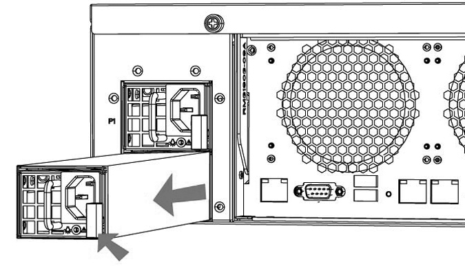
Caution: Put the defective power supply unit aside; wait until it cools down before touching it.
3. Slide in the new power supply until it mates with the back connectors in the chassis.
When the power supply unit is pushed all the way in, the button clicks to the right.
4. Plug the AC power cord into the new power supply unit.
Replacing memory
This section describes how to replace memory in the xx50 appliances.
DIMM slot locations
Memory modules and slot locations vary according to the motherboard in your appliance. Before you begin, you must obtain the correct replacement memory and slot location from Riverbed Support. The following sections identify the slot location for the memory modules according to the hardware platform.
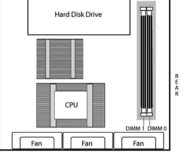
DIMM slot locations in SteelHead 150, 250, and 550 appliances
Figure: Memory module slots in SteelHead 150, 250, and 550 appliances shows the memory module slot locations for SteelHead 150, 250, and 550 appliances.
Figure: Memory module slots in SteelHead 150, 250, and 550 appliances
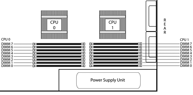
DIMM slot locations in Interceptor 9350 appliances
Figure: Memory module slots in Interceptor 9350 appliances shows the memory module slot locations for Interceptor 9350 appliances.
Figure: Memory module slots in Interceptor 9350 appliances
Replacing memory modules in SteelHead 150, 250, and 550 appliances
This section describes how to replace memory modules in a SteelHead 150, 250, and 550 appliance.
Before you begin, work with Riverbed Support at https://support.riverbed.com to determine the type of memory for the motherboard in your appliance and to determine the correct slot location for the memory. Memory modules and slot locations vary according to the motherboard in your appliance.
When replacing memory, you must use approved memory modules. Contact your Riverbed sales representative to obtain the correct memory modules.
Note: When you replace memory modules, you must wear a grounded ESD antistatic strap to protect the hardware against electrostatic discharge. Make sure that the strap makes skin contact prior to handling equipment. For details, see
Electrostatic discharge guidelines.
To replace the memory modules
1. Power down the system.
2. Disconnect the appliance from the electrical outlet and peripherals.
3. Remove the two locking screws on the back of the chassis.
Figure: Removing the locking screws
4. Position your thumbs on the top of the appliance and slide the cover back from the chassis.
5. Carefully lift the cover away from the appliance.
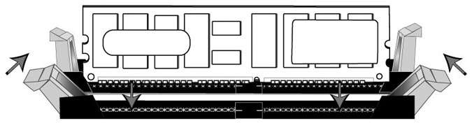
6. Press the ejector tabs on the memory slots down and outward, and gently pull the memory module out of the slot.
Caution: Be careful not to touch the adjacent power supply unit. Touching the power supply unit could cause electric shock.
Figure: Accessing the memory modules
7. If you are replacing memory, remove the existing memory module and replace it with the approved memory module.
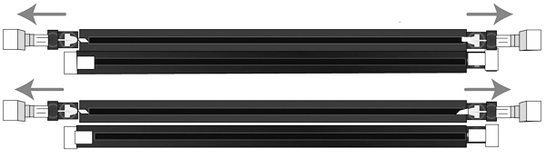
8. Align the memory-module edge connector with the slot alignment keys and insert it into the slot. The module slot has two alignment keys that allow you to install the module in only one direction.
Figure: Inserting and securing the memory module in the DIMM slot
9. Press down on the memory module with your thumbs while pulling up on the ejectors with your index fingers to lock the module into the slot.
10. Ensure that all ejector tabs are in the upright locked position.
11. Replace the chassis cover.
Replacing memory modules in 1U xx50 appliances
This section describes how to replace memory modules in a 1U appliance. Before you begin, you must obtain the correct replacement memory and slot location from Riverbed Support. Memory modules and slot locations vary according to the motherboard in your appliance.
Contact Riverbed Support at https://support.riverbed.com to determine the type of memory and slot location for the motherboard in your appliance.
Note: When you replace memory modules, you must wear a grounded ESD antistatic strap to protect the hardware against electrostatic discharge. Make sure that the strap makes skin contact prior to handling equipment. For details, see
Electrostatic discharge guidelines.
To replace the memory modules
1. Power down the system.
2. Disconnect the appliance from the electrical outlet and peripherals.
3. Carefully lift the cover away from the appliance.
4. Press the ejector tabs on the memory slots down and outward, and gently pull the memory module out of the slot.
Figure: Accessing the memory modules
5. Remove the existing memory module and replace it with an approved memory module of the same size.
Note: Replacing the existing memory module with a module of a different size causes the system to fail. You must use approved memory modules. Contact Riverbed Support at https://support.riverbed.com to obtain the correct memory modules.
6. Align the memory-module edge connector with the slot alignment keys and insert it into the slot. The module slot has two alignment keys that allow you to install the module in only one direction.
Figure: Inserting the memory modules into the connector slot and securing
7. Press down on the memory module with your thumbs while pulling up on the ejectors with your index fingers to lock the module into the slot.
8. Ensure that all ejector tabs are in the upright locked position.
9. Repeat Step 3 to Step 7 of this procedure to install the remaining memory modules.
10. Replace the chassis cover.
Replacing memory modules in 3U xx50 appliances
This section describes how to replace memory modules in 3U appliances. Before you begin you must obtain the correct replacement memory and slot location from Riverbed Support. Memory modules and slot locations vary according to the motherboard in your appliance.
Contact Riverbed Support at https://support.riverbed.com to determine the type of memory and slot location for the motherboard in your appliance.
Note: When you replace memory modules, you must wear a grounded ESD antistatic strap to protect the hardware against electrostatic discharge. Make sure that the strap makes skin contact prior to handling equipment. For details, see
Electrostatic discharge guidelines.
To remove the appliance cover
1. Power down the system.
2. Disconnect the appliance from the electrical outlet and peripherals.
3. Remove the top cover of the chassis.
To access the memory modules in the Interceptor 9350 appliances, you must remove the appliance cooling shroud. The following procedure describes the necessary steps to remove the cooling shroud.
To remove the cooling shroud
1. Using a magnetic Phillips screwdriver, remove the two screws securing the cooling shroud to the motherboard.
Figure: Removing the securing screws
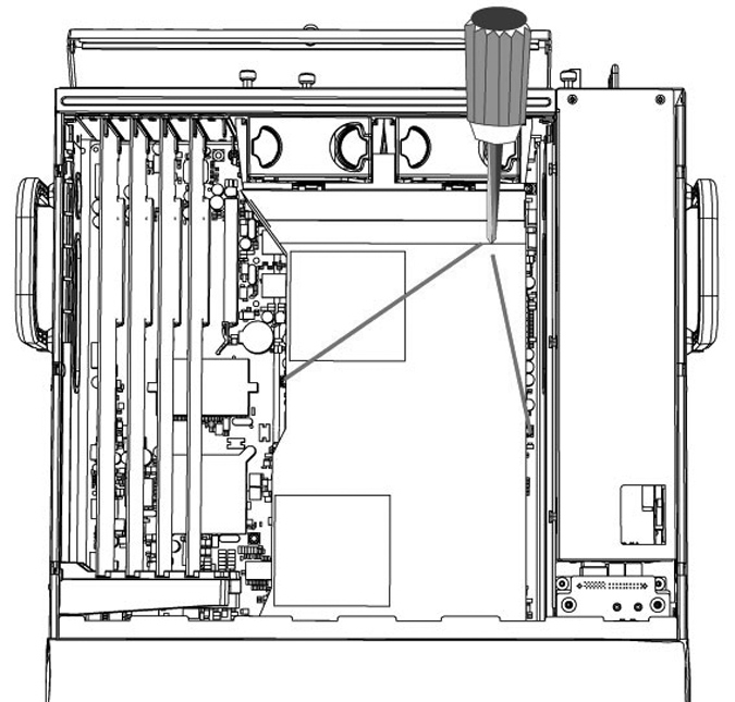
2. Loosen the motherboard locking screw at the back of the chassis and pull the motherboard handle downward and slide the motherboard out 1 to 2 inches from the chassis to release the cooling shroud. Lift the cooling shroud straight up and out of the appliance.
Caution: Be careful not to damage any surrounding components when removing and installing the cooling shroud. Lift the shroud straight up to avoid damaging any components of the shroud.
Figure: Sliding the motherboard outward
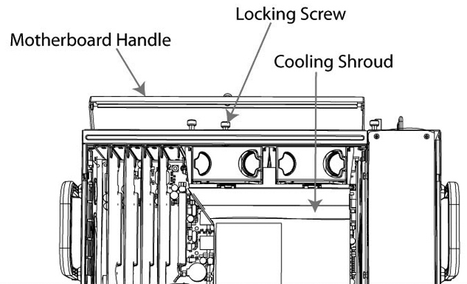
to release the cooling shroud
To replace the memory modules
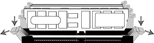
1. Press the ejector tabs on the memory module slot down and outward and gently pull the memory module out of the slot.
Figure: Accessing the memory modules
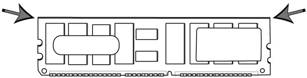
2. Hold the memory module on the outside edges to prevent damage to the module.
Figure: Proper handling of the memory module
3. Remove the existing memory module and replace it with an approved memory module of the same size.
Note: Replacing the existing memory module with a module of a different size causes the system to fail. You must use approved memory modules. Contact Riverbed Support at https://support.riverbed.com to obtain the correct memory modules.
4. Align the memory-module edge connector with the slot alignment keys and insert it into the slot. The module slot has two alignment keys that allow you to install the module in only one direction.
Figure: Inserting the memory modules into the connector slot and securing
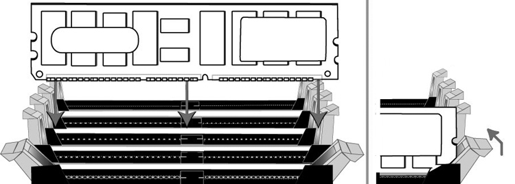
5. Press down on the memory module with your thumbs while pulling up on the ejectors with your index fingers to lock the module into the slot.
6. Ensure that all ejector tabs are in the upright locked position.
7. Repeat Steps 3 to Step 7 of this procedure to install the remaining memory modules.
8. Replace the chassis cover.
Replacing fans
The following sections describe how to replace fans in the SteelHead xx50 appliances. These appliances are equipped with hot-swappable fans.
Determining fan status
This section describes how to determine the status of individual fans in the appliance.
To determine fan status
1. Connect to the CLI.
For details, see the Riverbed Command-Line Interface Reference Manual.
2. At the system prompt, enter show stats fan:
amnesiac> show stats fan
FanId RPM Min RPM Status
0 4963 1080 ok
1 4963 1080 ok
2 4821 1080 ok
3 4963 1080 ok
4 4963 1080 ok
5 4821 1080 ok
The output and number of fans will vary depending on your appliance.
Replacing fans in the Interceptor 9350 appliances
This section describes how to replace fans in the Interceptor 9350. These appliances are equipped with four hot-swappable fans at the front of the chassis and two hot-swappable fans at the back of the chassis.
Note: You must use approved fans. To order fans, contact your sales representative.
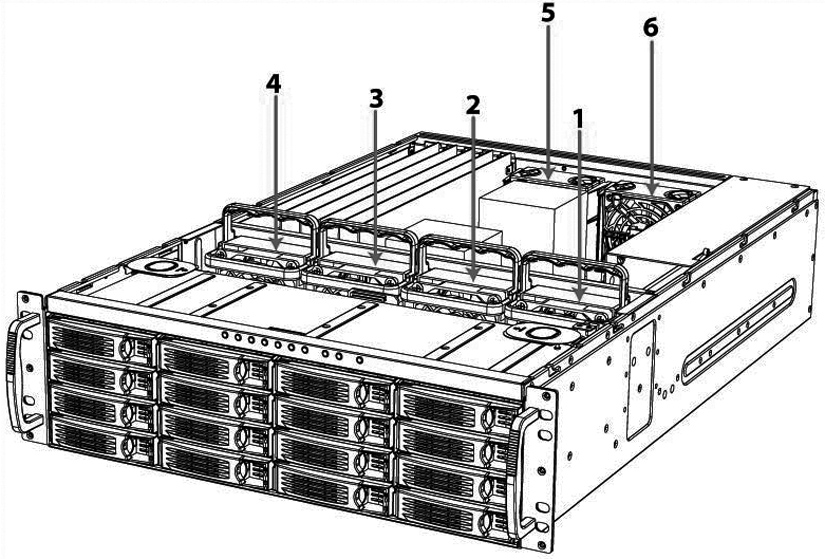
Fan locations
This section provides an overview of fan locations and fan labels in Interceptor 9350. These appliances are equipped with four fans at the front of the chassis and two fans at the back.
Fan ID | Physical Label |
1 | Fan 1 |
2 | Fan 2 |
3 | Fan 3 |
4 | Fan 4 |
5 | Fan 5 |
6 | Fan 6 |
Figure: Interceptor 9350 fan layout with fan ID numbers
To replace the front fans
1. To open the bezel, press the buttons on each side of the bezel and pull toward you.
The bezel remains attached to the appliance on hinges.
Figure: Opening the appliance bezel
2. To remove the front appliance cover, press in the two buttons on top of the cover and slide the cover forward, and then lift up and away from the chassis.
Figure: Removing the front appliance cover
3. Identify the faulty fan.
4. Pull the fan release lever upwards and pull the fan up from the chassis.
Figure: Releasing the fan
5. Plug the replacement fan into the chassis.
6. Replace the chassis front cover.
To replace the front cover, insert the rear edge of the front cover below the front edge of the rear cover.
Note: The RiOS IPMI alarm triggers when the chassis cover opens on these appliances while the system is running. To clear this alarm, run the clear hardware error-log command in the CLI. For details, see the Riverbed Command-Line Interface Reference Manual.
To replace the rear fans
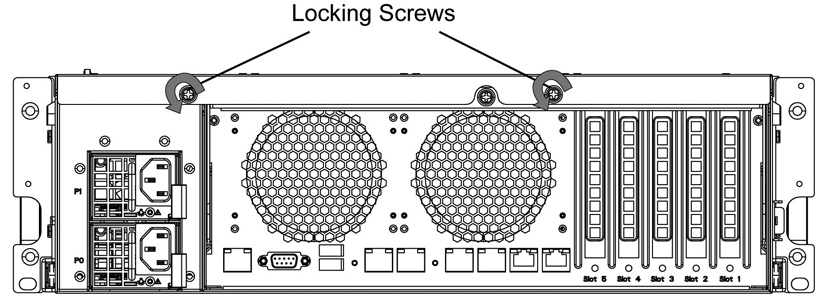
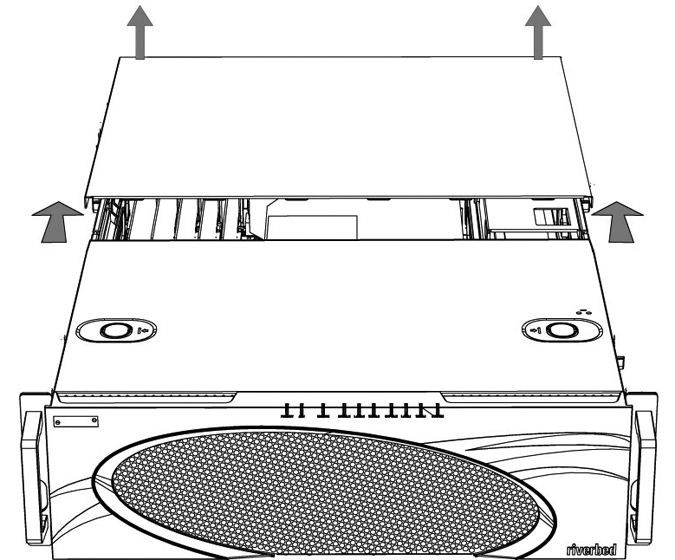
1. To remove the rear appliance cover, loosen the two locking screws on the back of the appliance.
Figure: Loosening the locking screws
2. Slide the rear cover backward several inches, and then lift up and away from the chassis.
Figure: Removing the rear cover from the chassis
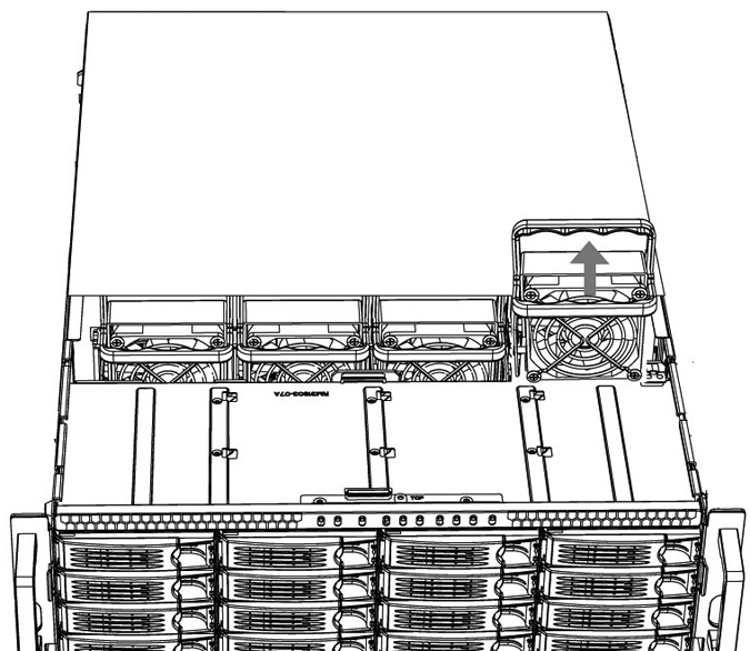
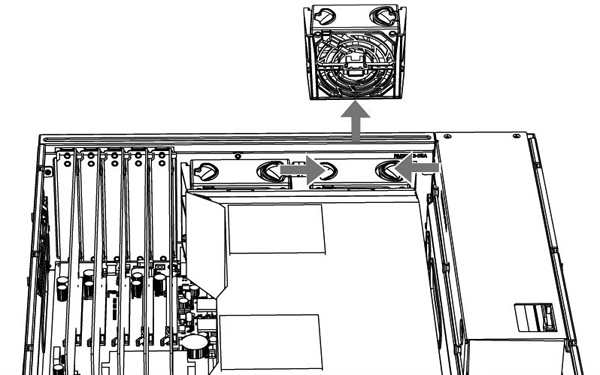
3. Identify the faulty fan.
4. Press the buttons on the top of the fan inwards and pull the fan up from the chassis.
Figure: Releasing the fan
5. Plug the replacement fan into the chassis.
6. Replace the chassis cover.
Note: The RiOS IPMI alarm is triggered when the chassis cover is opened on these appliances while the system is running. To clear this alarm, enter the clear hardware error-log command in the CLI. For details, see the Riverbed Command-Line Interface Reference Manual.
Replacing the motherboard in SteelHead 7050 appliances
For the SteelHead 7050 appliance, you can replace the motherboard. Work with Riverbed Support to complete these steps.
Note: A video showing these instructions is on the Riverbed Support Site:
https://support.riverbed.com/kb/multimedia.htm.
To replace a motherboard in a 7050 appliance
1. Power down the system.
2. Disconnect the power cord.
3. Remove the cover.
4. Loosen the motherboard locking screw at the back of the chassis and pull the motherboard handle downward.
The motherboard will slide out 1 to 2 inches from the chassis.
5. Continue sliding the motherboard completely from the chassis.
Caution: Be sure to use both hands as the motherboard is heavy.
6. Following the same procedure, remove the replacement motherboard from the chassis.
Each motherboard ships within a chassis.
7. Place the two motherboards side by side.
This helps transfer the appropriate components.
8. Using a Phillips screwdriver, remove the flash drive from the replacement motherboard.
9. Discard this flash drive.
10. Remove the flash drive from the failed motherboard and add it to the replacement motherboard.
Align the pins and secure the flash drive with the Phillips screw.
11. Move the network cards from the failed motherboard to the replacement motherboard.
Move the cards one at a time and keep the cards in the same positions. You will need to remove the slot covers for each network card to transfer. See the Network Interface Card Installation Guide for details.
12. Move the SDR acceleration card to the new motherboard.
Use the same procedure as you did with the network cards.
13. Insert the new motherboard into the chassis. Carefully align it inside the chassis, and slide it into place.
14. For the last inch, move the handle into the upright position and secure it with the locking screw.
15. Replace the back cover and secure it with the fasteners.
16. Connect the power and start the appliance.
17. From the command line, enter configuration mode and enter the show licenses command.
The output indicates the existing licenses are invalid.
18. Write down the MAC addresses of primary, AUX, lan0_0, wan0_0, lan0_1, and wan0_1.
19. Enter the CLI command support motherboard update.
Note: After you enter the command, do not press Ctrl+C before the command completes. You will destroy the BIOS. Restart the appliance when prompted using the reload command.
The commands take a while to complete as they copy the BIOS and reconfigure the MAC addresses.
The support motherboard update command is a hidden command.
20. When prompted, reboot the appliance using the reload command.
21. Once the appliance reboots, enter the show licenses command and ensure that the licenses are valid.
22. Verify the MAC addresses of the primary and AUX interfaces.
The primary and AUX interfaces should have new MAC addresses. The MAC addresses of lan0_0, wan0_0, lan0_1, and wan0_1 remain the same.