Interceptor Clusters
This chapter discusses different types of Interceptor deployments. Typical Interceptor deployments have multiple Interceptors and SteelHeads, and usually all appliances have more than one enabled and configured in-path interface. This chapter includes the following sections:
You can use multiple Interceptors to ensure that optimization occurs even when there are multiple, physically separated paths to the WAN or to ensure that optimization continues during a planned or unplanned Interceptor outage. Use multiple SteelHeads to ensure redundancy or to specify that certain applications, subnets, and hosts are optimized by different SteelHeads.
Designing an Interceptor deployment requires not only configuring the relationship between the Interceptors and SteelHeads, but also understanding how data is exchanged between the SteelHead and Interceptors, and how this data exchange interacts with the existing network, security, and monitoring infrastructure.
SteelHead placement and configuration
This section discusses SteelHead placement and configuration and includes the following topics:
The Interceptor can redirect packets for optimization to up to 25 clustered SteelHeads. For details on how to configure the process that an Interceptor uses to determine which SteelHead to use when redirecting traffic, see
Traffic Redirection. For details on VLAN segregation limitations, see
Feature compatibility and limitations.
You can’t use SteelHeads in an Interceptor cluster simultaneously with other deployment methods. For example, a SteelHead can’t be both a member of an Interceptor cluster while also a part of a WCCP cluster.
In addition to redirected packets, Interceptors and SteelHeads communicate using TCP connections (TCP destination port 7850 by default) between their in-path interface IP addresses. Because the information exchanged on these connections is vital during autodiscovery, if there is heavy congestion on the LAN network between cluster members, contact your Riverbed account team or Riverbed Support for assistance to use DSCP marking to prioritize cluster traffic.
LAN-side versus WAN-side SteelHead placement
Figure: SteelHead placed on either the WAN or LAN side of the Interceptor shows how to connect SteelHeads to the local network on either the LAN or WAN side of the Interceptor. For most deployments, LAN-side SteelHead placement minimizes the amount of traffic that traverses the Interceptor. You can’t cable the SteelHead directly to the Interceptor.
SteelHead placed on either the WAN or LAN side of the Interceptor
In general, placing SteelHeads on the LAN side of the Interceptor typically minimizes the amount of traffic that the Interceptor must handle for optimized traffic. For LAN-side SteelHead placement, the local-host-to-remote-host traffic and reduced SteelHead-to-SteelHead traffic traverse the Interceptor, versus the bidirectional unreduced LAN-side traffic between the SteelHead and the local hosts.
In virtual in-path Interceptor deployments, don’t deploy the SteelHeads in situations in which the traffic traverses a router-redirecting interface. This configuration causes traffic from the SteelHead to be unnecessarily redirected back to the Interceptor.
For more details on virtual in-path Interceptor deployments, see
Unsupported virtual in-path Interceptor deployment.
Layer-2 versus Layer-3 connectivity
The SteelHead and Interceptor in-path IP addresses can be on the same or different subnets. The actions taken to redirect traffic are the same during autodiscovery and optimization. Unlike when you use WCCP to redirect traffic to a SteelHead, there is no resource use or MTU concerns from having the SteelHead and Interceptor in-path IP addresses on different subnets.
Multiple SteelHead link support
A SteelHead can have multiple in-path interfaces configured, which means that the SteelHead Interceptor can use multiple IP addresses to reach the same SteelHead. Before SteelHead Interceptor 6.5 and SteelHead 9.6, the SteelHead Interceptor could only redirect traffic to one in-path interface on the SteelHead. Essentially, the SteelHead Interceptor used an active/backup method when selecting an in-path interface for redirecting traffic to the SteelHead.
In SteelHead Interceptor 6.5, all configured in-path interfaces can be used in an active/active method. To use the active/active method, the SteelHead Interceptor must have the main-ip address and the additional‑IP addresses configured for the SteelHead, along with enabling support for multiple SteelHead links.
The IP address of the interface is logically associated with the in-path interface, but physically, the WAN interface is actually cabled to the network, as shown in
Figure: Example deployment of a SteelHead with two configured in-path interfaces.
Example deployment of a SteelHead with two configured in-path interfaces
If the IP address for that interface becomes unreachable, the Interceptor tries to reach every SteelHead IP address from each of the Interceptor’s in-path interfaces before considering the SteelHead entirely inaccessible.
If a SteelHead in-path interface fails or becomes unreachable from the Interceptor, any existing connections that were being optimized by the SteelHead with that in-path interface are either reset or timed out, depending on the application in use.
When you configure the Interceptor load-balancing rules, only configure a single in-path IP address per SteelHead in the rule set. For example, an Interceptor can have all of the in-path IP addresses of the SteelHeads configured as a SteelHead cluster, but only the inpath0_0 IP address is used in the load-balancing rules.
1. Connect to the SteelHead and enter the following commands:
interface inpath0_0 ip address 172.16.0.10 /24
ip in-path-gateway inpath0_0 172.16.0.1
interface inpath0_1 ip address 172.17.0.10 /24
ip in-path-gateway inpath0_1 172.17.0.1
in-path enable
in-path oop enable
steelhead communication enable
steelhead communication multi-interface enable
steelhead name interceptor main-ip 10.1.0.7
steelhead name interceptor additional-ip 10.2.0.8
2. Connect to the Interceptor and enter the following commands:
in-path interface inpath0_0 enable
interface inpath0_0 ip address 10.1.0.7 /24
ip in-path-gateway inpath0_0 10.1.0.1
ip in-path route inpath0_0 172.16.0.0 255.255.255.0 10.1.0.2
ip in-path route inpath0_0 172.17.0.0 255.255.255.0 10.1.0.2
interface inpath0_1 ip address 10.2.0.8 /24
ip in-path-gateway inpath0_1 10.2.0.1
ip in-path route inpath0_1 172.16.0.0 255.255.255.0 10.2.0.2
ip in-path route inpath0_1 172.17.0.0 255.255.255.0 10.2.0.2
steelhead communication multi-interface enable
steelhead name steelhead main-ip 172.16.0.10
steelhead name steelhead additional-ip 172.17.0.10
Multiple SteelHead support
The SteelHeads in a cluster have each clustered Interceptor configured as a connection-forwarding neighbor, using the steelhead communication commands. Each clustered SteelHead typically has each Interceptor inpath0_0 IP address configured as the clustered SteelHead main-ip and other Interceptor in‑path interfaces configured as additional IP addresses. Don’t configure one clustered SteelHead to know anything about the other clustered SteelHead.
You can use the RiOS data store synchronization between any local pair of SteelHeads, including SteelHead pairs in an Interceptor cluster. You typically perform data synchronization when the load-balance configuration on the Interceptors causes similar traffic to be sent to the pair of SteelHeads.
The SteelHeads in an Interceptor cluster don’t need to be the same model. The Interceptor can make redirection decisions that account for different SteelHead capacities. For details, see
Traffic Redirection.
Multiple SteelHeads with multiple interfaces in an Interceptor cluster
The configuration for SteelHead 1 has no information regarding SteelHead 2. SteelHeads deployed in an Interceptor cluster must never have other SteelHeads configured as connection-forwarding clustered SteelHeads.
1. Connect to SteelHead 1 and enter the following commands:
interface inpath0_0 ip address 172.16.0.10 /24
ip in-path-gateway inpath0_0 172.16.0.1
interface inpath0_1 ip address 172.17.0.10 /24
ip in-path-gateway inpath0_1 172.17.0.1
in-path enable
in-path oop enable
steelhead communication enable
steelhead communication multi-interface enable
steelhead name interceptor main-ip 10.1.0.7
steelhead name interceptor additional-ip 10.2.0.8
2. Connect to the SteelHead 2 and enter the following commands:
interface inpath0_0 ip address 172.16.0.11 /24
ip in-path-gateway inpath0_0 172.16.0.1
interface inpath0_1 ip address 172.17.0.11 /24
ip in-path-gateway inpath0_1 172.17.0.1
in-path enable
in-path oop enable
steelhead communication enable
steelhead communication multi-interface enable
steelhead name interceptor main-ip 10.1.0.7
steelhead name interceptor additional-ip 10.2.0.8
3. Connect to the Interceptor and enter the following commands:
in-path interface inpath0_0 enable
interface inpath0_0 ip address 10.1.0.7 /24
ip in-path-gateway inpath0_0 10.1.0.1
ip in-path route inpath0_0 172.16.0.0 255.255.255.0 10.1.0.2
ip in-path route inpath0_0 172.17.0.0 255.255.255.0 10.1.0.2
interface inpath0_1 ip address 10.2.0.8 /24
ip in-path-gateway inpath0_1 10.2.0.1
ip in-path route inpath0_1 172.16.0.0 255.255.255.0 10.2.0.2
ip in-path route inpath0_1 172.17.0.0 255.255.255.0 10.2.0.2
steelhead communication multi-interface enable
steelhead name steelhead1 main-ip 172.16.0.10
steelhead name steelhead1 additional-ip 172.17.0.10
steelhead name steelhead2 main-ip 172.18.0.11
steelhead name steelhead1 additional-ip 172.19.0.11
Firewall and monitoring interaction
You can deploy the Interceptor at sites with firewalls, intrusion prevention systems (IPS), intrusion detection systems (IDS), or other network security and monitoring devices. Design the Interceptor deployment so that these devices aren’t located in the flow of redirected packets between the Interceptor and SteelHead, because the redirected packets might either prevent the security devices from properly tracking flows or generate unnecessary alarms. Place the network security or monitoring devices on the WAN or LAN side of the complete Interceptor and SteelHead cluster.
If you use a firewall or other security device as a Layer-3 next hop for the Interceptor or SteelHead, configure the routing and default gateway configuration on the Interceptor and SteelHead so the firewall detects all or none of the packets associated with the autodiscovery process.
For details on packet flow between the SteelHead and Interceptors, see
Traffic Redirection. For details on routing and default gateways, see
Default gateway and routing configuration.
Relative placement of a firewall, SteelHead, and Interceptor
This section demonstrates how to apply placement guidelines for firewalls, SteelHeads, and Interceptors. It includes the following topics:
Figure: An example of a site using firewalls to perform deep packet inspection shows a site where firewalls are used to perform connection tracking and deep packet inspection on traffic arriving from the WAN, and they also must detect the nonoptimized, or native, data for any optimized traffic.
An example of a site using firewalls to perform deep packet inspection
Disruptive firewall placements
Figure: Example of how not to deploy an Interceptor shows Interceptors placed outside the firewalls and LAN infrastructure. The SteelHeads are placed on the LAN side of the Interceptor, as recommended.
The SteelHead placement in
Figure: Example of how not to deploy an Interceptor is disruptive for the firewalls for at least two reasons:
n The firewalls detect redirected packets from the Interceptors to the SteelHead. For this method of detection to function, you must configure the firewall to allow the two forms of redirection:
– GRE traffic from the Interceptors to the SteelHeads
– Any TCP traffic to the SteelHead in-path IP interfaces
The company security policy might not permit you to enable either of these redirection types.
n The firewalls don’t detect the full data flow for any optimized connection. Traffic from the SteelHeads to the hosts at the location doesn’t flow through the firewall. Because the data from that traffic originated at a remote host, you must scan the traffic by the firewall.
Example of how not to deploy an Interceptor
Figure: SteelHead deployed on the WAN side of the Interceptor shows the Interceptors are deployed as before, but the SteelHeads are now placed on the WAN side of the Interceptor. This placement prevents the firewalls from detecting any Interceptor-to-SteelHead traffic, and the firewalls can detect the native form of any optimized connection. We don’t recommend this configuration because placing SteelHeads logically on the WAN side of the Interceptor typically forces more traffic through the Interceptor than the alternative.
SteelHead deployed on the WAN side of the Interceptor
Firewall placement best practices
We recommend the firewall, SteelHead, and Interceptor placement shown in
Figure: Best firewall, SteelHead, and Interceptor relative deployment option. This figure shows that the Interceptors can cover all of the paths to and from the WAN; the SteelHeads are on the LAN side of the Interceptor, and the firewalls detect the LAN-side traffic so that they can perform all necessary content inspection.
Best firewall, SteelHead, and Interceptor relative deployment option
Interceptor relationships
This section discusses relationships between multiple Interceptors. This section includes the following topics:
There are several reasons to deploy more than one Interceptor at the same site:
n To provide redirect coverage for all paths to the WAN
n To provide redundancy in case of an Interceptor failure
n To ensure that the amount of traffic traversing an Interceptor doesn’t exceed its specifications
n To ensure that asymmetrically routed TCP connections are redirected to the correct optimizing SteelHead
If you deploy more than one Interceptor per site, you must configure each Interceptor to interact with every other Interceptor in one of two ways:
n Failover Interceptor
n Cluster Interceptor
You can configure the Interceptor to be either a serially connected failover Interceptor acting as a backup for the same network paths, or an Interceptor cluster that covers different network paths or is used in a virtual in-path cluster.
You can configure Interceptor clusters in both serial and parallel deployments. For details, see
Deploying quad Interceptors. However, you can configure only serial Interceptors for mutual failover. Interceptors communicate with each other through TCP connections (with a default destination port 7860) using their in-path interface IP addresses. We recommend that you use the default gateway and routing setup to ensure LAN-side next hops to reach other Interceptor in-path interfaces if they are on different subnets.
Because the information exchanged on these connections is vital during autodiscovery, you can manually configure the DSCP markings. This configuration might be beneficial in environments where the LAN infrastructure can recognize and prioritize traffic based on DSCP values. If there is heavy congestion on the LAN network connecting between Interceptors and SteelHeads, contact your Riverbed account team or Riverbed Support for assistance to use DSCP marking to prioritize cluster traffic.
Deploying failover Interceptors
You must deploy failover Interceptors physically in-path on all of the same physical links. Failover Interceptors share information about any flows that are being redirected, as well as information about flows that are going through the autodiscovery process.
For a failover Interceptor configuration with multiple in-path interfaces, you must configure the IP addresses for all interfaces. We recommend that you enable the multi-interface configuration option, even if you use only a single in-path interface.
If a failover Interceptor becomes unavailable, either due to network connectivity issues or because one Interceptor has suffered a failure, the remaining Interceptor continues to redirect packets for existing optimized connections and for any new connections, so that autodiscovery (and potential optimization) can occur.
Serial failover Interceptors are similar to SteelHeads in a serial cluster, in which even in normal operation both Interceptors are actively redirecting traffic.
Interceptors deployed in a failover configuration
You can configure only one failover Interceptor per Interceptor. For details on how failover Interceptors communicate, see
Traffic Redirection.
In Interceptor 3.0 and later, you configure a failover Interceptor in the Management Console exactly as you would an Interceptor cluster prior to 3.0, but select Use for Failover to denote that this Interceptor is a serial failover Interceptor. Alternatively, from the CLI, you can enable the failover interceptor command.
1. Connect to Interceptor 1 and enter the following commands:
interface inpath0_0 ip address 10.1.0.6 /24
in-path interface inpath0_0 enable
ip in-path-gateway inpath0_0 10.1.0.1
ip in-path route inpath0_0 172.16.0.0 255.255.255.0 10.1.0.2
ip in-path route inpath0_0 10.2.0.0 255.255.255.0 10.1.0.2
interface inpath0_1 ip address 10.2.0.6 /24
in-path interface inpath0_1 enable
ip in-path-gateway inpath0_1 10.2.0.1
ip in-path route inpath0_1 172.16.0.0 255.255.255.0 10.2.0.2
ip in-path route inpath0_1 10.1.0.0 255.255.255.0 10.2.0.2
failover interceptor name interceptor2 main-ip 10.1.0.7
failover interceptor name interceptor2 additional-ip 10.2.0.7
steelhead communication multi-interface enable
steelhead name steelhead1 main-ip 172.16.0.10
2. Connect to Interceptor 2 and enter the following commands:
interface inpath0_0 ip address 10.1.0.7 /24
in-path interface inpath0_0 enable
ip in-path-gateway inpath0_0 10.1.0.1
ip in-path route inpath0_0 172.16.0.0 255.255.255.0 10.1.0.2
ip in-path route inpath0_0 10.2.0.0 255.255.255.0 10.1.0.2
interface inpath0_1 ip address 10.2.0.7 /24
in-path interface inpath0_1 enable
ip in-path-gateway inpath0_1 10.2.0.1
ip in-path route inpath0_1 172.16.0.0 255.255.255.0 10.2.0.2
ip in-path route inpath0_1 10.1.0.0 255.255.255.0 10.2.0.2
failover interceptor name interceptor2 main-ip 10.1.0.6
failover interceptor name interceptor2 additional-ip 10.2.0.6
steelhead communication multi-interface enable
steelhead name steelhead1 main-ip 172.16.0.10
Deploying Interceptors in clusters
Clustered Interceptors, formerly called redirect peers, share information about any flows that are redirected or are going through the autodiscovery process. You deploy clustered Interceptors physically in-path on different physical links or within a virtual in-path cluster. In version 3.0 and later, you can configure clustered Interceptors in the Interceptor Management Console in the Networking > Network Services: SteelHead Interceptor page or in the CLI using the interceptor commands.
Don’t select the Use with Failover check box in the Interceptor Management Console or use the failover interceptor command to configure Interceptors that are cabled in parallel.
You must configure clustered Interceptors with multiple in-path interfaces to have the IP addresses for all interfaces, and you must enable the multi-interface option. (We recommend that you enable the multi-interface option, even if only a single in-path interface is used.)
An Interceptor might have many clustered Interceptors configured. Although there is no hard limit to the number of clustered Interceptors supported, the communication required per Interceptor during autodiscovery acts as a limiting factor to the maximum number. Riverbed tests up to eight clustered appliances per Interceptor. For details on how Interceptor clusters communicate, see
Traffic Redirection.
If any clustered Interceptor becomes unavailable, another Interceptor continues to redirect packets for new and existing optimized connections. When an Interceptor redirects packets for autodiscovery on newly established connections, the Interceptor is controlled by a configuration setting called redirect allow-failure.
Avoid using redirect operations in your network design if you use the allow-failure setting to ensure continuing redirection, so that this doesn’t result in asymmetric routing without traffic redirection. For details, see
Cluster member failures.
Interceptor deployed in a cluster
1. Connect to Interceptor 1 and enter the following commands:
interface inpath0_0 ip address 10.1.0.6 /24
in-path interface inpath0_0 enable
ip in-path-gateway inpath0_0 10.1.0.1
ip in-path route inpath0_0 10.3.0.0 255.255.255.0 10.1.0.2
ip in-path route inpath0_0 10.4.0.0 255.255.255.0 10.1.0.2
ip in-path route inpath0_0 172.16.0.0 255.255.255.0 10.1.0.2
interface inpath0_1 ip address 10.2.0.6 /24
in-path interface inpath0_1 enable
ip in-path-gateway inpath0_1 10.2.0.1
ip in-path route inpath0_1 10.3.0.0 255.255.255.0 10.2.0.2
ip in-path route inpath0_1 10.4.0.0 255.255.255.0 10.2.0.2
ip in-path route inpath0_1 172.16.0.0 255.255.255.0 10.2.0.2
interceptor communication multi-interface enable
interceptor name interceptor2 main-ip 10.3.0.6
interceptor name interceptor2 additional-ip 10.4.0.6
steelhead communication multi-interface enable
steelhead name steelhead1 main-ip 172.16.0.10
2. Connect to Interceptor 2 and enter the following commands:
interface inpath0_0 ip address 10.3.0.6 /24
in-path interface inpath0_0 enable
ip in-path-gateway inpath0_0 10.3.0.1
ip in-path route inpath0_0 10.1.0.0 255.255.255.0 10.3.0.2
ip in-path route inpath0_0 10.2.0.0 255.255.255.0 10.3.0.2
ip in-path route inpath0_0 172.16.0.0 255.255.255.0 10.3.0.2
interface inpath0_1 ip address 10.4.0.6 /24
in-path interface inpath0_1 enable
ip in-path-gateway inpath0_1 10.4.0.1
ip in-path route inpath0_1 10.1.0.0 255.255.255.0 10.4.0.2
ip in-path route inpath0_1 10.2.0.0 255.255.255.0 10.4.0.2
ip in-path route inpath0_1 172.16.0.0 255.255.255.0 10.4.0.2
interceptor communication multi-interface enable
interceptor name interceptor1 main-ip 10.1.0.6
interceptor name interceptor1 additional-ip 10.2.0.6
steelhead communication multi-interface enable
steelhead name steelhead1 main-ip 172.16.0.10
Unsupported deployments
Riverbed supports only those Interceptor deployments in which each appliance in the Interceptor pair in the cluster is either configured as a failover Interceptor and located on the same in-path links or is configured as a clustered Interceptor and doesn’t have any common in-path links.
Figure: Example of an unsupported Interceptor deployment shows an example of an unsupported deployment. Interceptors 1 and 2 can’t be failover Interceptors because they aren’t deployed on all of the same in-path links. They can’t be clustered Interceptors because they have a common in-path link.
Example of an unsupported Interceptor deployment
Cluster member failures
If an Interceptor that is part of a cluster fails, the impact on the cluster and optimization depends on whether you:
n enabled fail-to-block mode on the failed Interceptor.
n configured the failed Interceptor for failover with any live Interceptors.
n enabled the redirect allow-failure setting (for the remaining Interceptors).
When an Interceptor fails or becomes unreachable, any remaining failover and clustered Interceptors continue to redirect packets for existing optimized connections to the appropriate SteelHead cluster. Enabling redundancy is useful for unplanned failures and for planned maintenance that might require disabling the failed Interceptor or temporarily removing it from the network.
If the failover appliance of an Interceptor becomes unavailable, either due to network connectivity issues or because the failover Interceptor has suffered a failure, the Interceptor continues to redirect packets for existing optimized connections, as well as for any new connections, so that autodiscovery (and potential optimization) can occur.
Figure: Failure of a failover Interceptor shows Interceptor 1 with failover Interceptor 2. You typically configure fail-to-wire mode (instead of fail-to-block) on Interceptors with failover, so that traffic continues to reach remaining failover Interceptors for redirection.
Failure of a failover Interceptor
You can configure how Interceptor clusters react to an Interceptor failure.
Figure: Failure of a cluster Interceptor shows failed Interceptor 1 with Interceptor 2. If you configure Interceptor 1 for fail-to-block, then all links to or from the WAN pass through Interceptor 2 after the failure. If you configure Interceptor 1 for fail-to-wire, there are links to and from the WAN without redirection coverage after the failure. TCP connections that are routed asymmetrically across links without redirection can’t be optimized. Therefore, an Interceptor must be able to detect if the unavailability of another appliance implies that there are links without redirection coverage.
Failure of a cluster Interceptor
If any clustered Interceptor becomes unavailable, another Interceptor continues to redirect packets for existing optimized connections. When that appliance redirects packets for autodiscovery on newly established connections, it is controlled by a configuration setting called redirect allow-failure. This setting is similar to the allow-failure feature on SteelHeads.
After a clustered Interceptor is unavailable, another Interceptor forwards packets for autodiscovery if the allow-failure setting is enabled. If the allow-failure setting is disabled, the Interceptor doesn’t redirect new connections until you:
n restore the failed clustered Interceptor.
n replace the failed Interceptor with a new appliance with the same in-path IP addresses.
n change the configuration of the live Interceptor.
The default setting for redirect allow-failure is disabled. You can configure the redirect allow-failure setting with the interceptor communication allow-failure enable command.
If a SteelHead fails or becomes unreachable, then an Interceptor stops redirecting packets for any optimized connections that were owned by the SteelHead. An Interceptor stops redirecting packets to the SteelHead for autodiscovery.
For details on the allow-failure feature on the SteelHead, see the
SteelHead Deployment Guide. For details on how to use multiple SteelHeads for redundancy, see
Traffic Redirection.
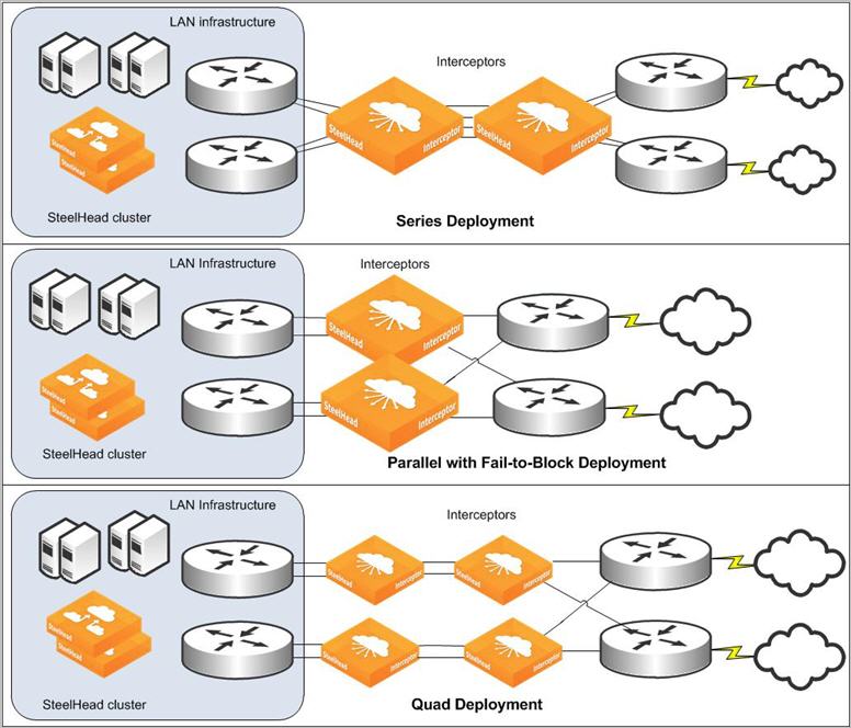
Standard cluster types
The Interceptor relationships and failure reaction features are typically combined in several ways for actual Interceptor deployments. You can deploy Interceptor clusters in the following ways:
Figure: Three primary types of Interceptor deployments: series, parallel with fail-to-block, and quad shows the three primary physical in-path types of deployments: series, parallel with fail‑to-block, and quad. In each of these deployment types, optimization of existing and new connections can continue despite the failure of any single Interceptor.
Three primary types of Interceptor deployments: series, parallel with fail-to-block, and quad
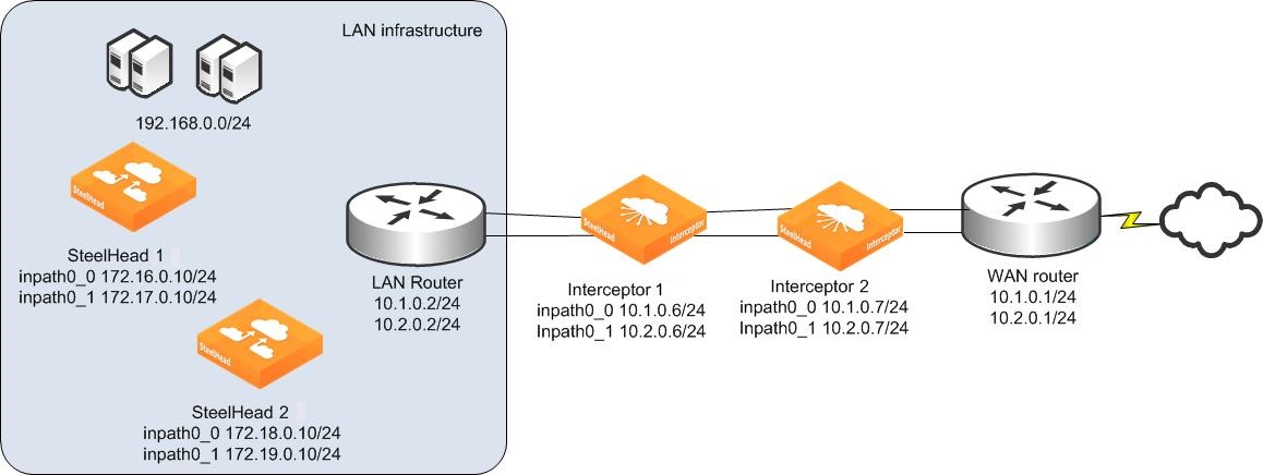
Deploying series Interceptors
In a series deployment, you install two Interceptors. You configure each Interceptor as the failover Interceptor for the other. Use the default fail-to-wire mode on all Interceptors. Optimization for existing and new connections can continue despite the failure of a single Interceptor.
Interceptor series deployment
1. Connect to SteelHead 1 and enter the following commands:
interface inpath0_0 ip address 172.16.0.10 /24
ip in-path-gateway inpath0_0 172.16.0.1
interface inpath0_1 ip address 172.17.0.10 /24
ip in-path-gateway inpath0_1 172.17.0.1
in-path enable
in-path oop enable
steelhead communication enable
steelhead communication multi-interface enable
steelhead name interceptor1 main-ip 10.1.0.6
steelhead name interceptor1 additional-ip 10.2.0.6
steelhead name interceptor2 main-ip 10.1.0.7
steelhead name interceptor2 additional-ip 10.2.0.7
2. Connect to SteelHead 2 and enter the following commands:
interface inpath0_0 ip address 172.18.0.10 /24
ip in-path-gateway inpath0_0 172.18.0.1
interface inpath0_1 ip address 172.19.0.10 /24
ip in-path-gateway inpath0_1 172.18.0.1
in-path enable
in-path oop enable
steelhead communication enable
steelhead communication multi-interface enable
steelhead name interceptor1 main-ip 10.1.0.6
steelhead name interceptor1 additional-ip 10.2.0.6
steelhead name interceptor2 main-ip 10.1.0.7
steelhead name interceptor2 additional-ip 10.2.0.7
3. Connect to Interceptor 1 and enter the following commands:
interface inpath0_0 ip address 10.1.0.6 /24
in-path interface inpath0_0 enable
ip in-path-gateway inpath0_0 10.1.0.1
ip in-path route inpath0_0 10.2.0.0 255.255.255.0 10.1.0.2
ip in-path route inpath0_0 172.16.0.0 255.255.255.0 10.1.0.2
ip in-path route inpath0_0 172.17.0.0 255.255.255.0 10.1.0.2
ip in-path route inpath0_0 172.18.0.0 255.255.255.0 10.1.0.2
ip in-path route inpath0_0 172.19.0.0 255.255.255.0 10.1.0.2
interface inpath0_1 ip address 10.2.0.6 /24
in-path interface inpath0_1 enable
ip in-path-gateway inpath0_1 10.2.0.1
ip in-path route inpath0_1 10.1.0.0 255.255.255.0 10.2.0.2
ip in-path route inpath0_1 172.16.0.0 255.255.255.0 10.2.0.2
ip in-path route inpath0_1 172.17.0.0 255.255.255.0 10.2.0.2
ip in-path route inpath0_1 172.18.0.0 255.255.255.0 10.2.0.2
ip in-path route inpath0_1 172.19.0.0 255.255.255.0 10.2.0.2
failover interceptor name interceptor2 main-ip 10.1.0.7
failover interceptor name interceptor2 additional-ip 10.2.0.7
steelhead communication multi-interface enable
steelhead name steelhead1 main-ip 172.16.0.10
steelhead name steelhead1 additional-ip 172.17.0.10
steelhead name steelhead2 main-ip 172.18.0.10
steelhead name steelhead2 additional-ip 172.19.0.10
4. Connect to Interceptor 2 and enter the following commands:
interface inpath0_0 ip address 10.1.0.7 /24
in-path interface inpath0_0 enable
ip in-path-gateway inpath0_0 10.1.0.1
ip in-path route inpath0_0 10.2.0.0 255.255.255.0 10.1.0.2
ip in-path route inpath0_0 172.16.0.0 255.255.255.0 10.1.0.2
ip in-path route inpath0_0 172.17.0.0 255.255.255.0 10.1.0.2
ip in-path route inpath0_0 172.18.0.0 255.255.255.0 10.1.0.2
ip in-path route inpath0_0 172.19.0.0 255.255.255.0 10.1.0.2
interface inpath0_1 ip address 10.2.0.7 /24
in-path interface inpath0_1 enable
ip in-path-gateway inpath0_1 10.2.0.1
ip in-path route inpath0_1 10.1.0.0 255.255.255.0 10.2.0.2
ip in-path route inpath0_1 172.16.0.0 255.255.255.0 10.2.0.2
ip in-path route inpath0_1 172.17.0.0 255.255.255.0 10.2.0.2
ip in-path route inpath0_1 172.18.0.0 255.255.255.0 10.2.0.2
ip in-path route inpath0_1 172.19.0.0 255.255.255.0 10.2.0.2
failover interceptor name interceptor1 main-ip 10.1.0.6
failover interceptor name interceptor1 additional-ip 10.2.0.6
steelhead communication multi-interface enable
steelhead name steelhead1 main-ip 172.16.0.10
steelhead name steelhead1 additional-ip 172.17.0.10
steelhead name steelhead2 main-ip 172.18.0.10
steelhead name steelhead2 additional-ip 172.19.0.10
Deploying parallel Interceptors with fail-to-block
In a parallel with fail-to-block deployment, you install two Interceptors and configure each as part of the same cluster. In both Interceptors, you disable the fail-to-wire mode and enable the allow-failure option. When an Interceptor fails, it prevents traffic from flowing through its in-path links. You can use this deployment when a network uses a routing or switching protocol that can cause the traffic flow after a failure to continue only along the remaining available paths to the WAN.
If both Interceptors fail, traffic is unable to reach the WAN. This scenario typically matches existing network designs that are configured to survive a single point of failure but might not survive double failures.
Interceptor parallel with fail-to-block deployment
1. Connect to SteelHead 1 and enter the following commands:
interface inpath0_0 ip address 172.16.0.10 /24
ip in-path-gateway inpath0_0 172.16.0.1
interface inpath0_1 ip address 172.17.0.10 /24
ip in-path-gateway inpath0_1 172.17.0.1
in-path enable
in-path oop enable
steelhead communication enable
steelhead communication multi-interface enable
steelhead communication allow-failure
steelhead name interceptor1 main-ip 10.1.0.6
steelhead name interceptor1 additional-ip 10.2.0.6
steelhead name interceptor2 main-ip 10.3.0.6
steelhead name interceptor2 additional-ip 10.4.0.6
2. Connect to SteelHead 2 and enter the following commands:
interface inpath0_0 ip address 172.18.0.10 /24
ip in-path-gateway inpath0_0 172.18.0.1
interface inpath0_1 ip address 172.19.0.10 /24
ip in-path-gateway inpath0_1 172.19.0.1
in-path enable
in-path oop enable
steelhead communication enable
steelhead communication multi-interface enable
steelhead communication allow-failure
steelhead name interceptor1 main-ip 10.1.0.6
steelhead name interceptor1 additional-ip 10.2.0.6
steelhead name interceptor2 main-ip 10.3.0.6
steelhead name interceptor2 additional-ip 10.4.0.6
3. Connect to Interceptor 1 and enter the following commands:
interface inpath0_0 ip address 10.1.0.6 /24
in-path interface inpath0_0 enable
no interface inpath0_0 fail-to-bypass enable
ip in-path-gateway inpath0_0 10.1.0.1
ip in-path route inpath0_0 10.3.0.0 255.255.255.0 10.1.0.2
ip in-path route inpath0_0 10.4.0.0 255.255.255.0 10.1.0.2
ip in-path route inpath0_0 172.16.0.0 255.255.255.0 10.1.0.2
ip in-path route inpath0_0 172.17.0.0 255.255.255.0 10.1.0.2
ip in-path route inpath0_0 172.18.0.0 255.255.255.0 10.1.0.2
ip in-path route inpath0_0 172.19.0.0 255.255.255.0 10.1.0.2
interface inpath0_1 ip address 10.2.0.6 /24
ip in-path-gateway inpath0_1 10.2.0.1
in-path interface inpath0_1 enable
no interface inpath0_1 fail-to-bypass enable
ip in-path route inpath0_1 10.3.0.0 255.255.255.0 10.2.0.2
ip in-path route inpath0_1 10.4.0.0 255.255.255.0 10.2.0.2
ip in-path route inpath0_1 172.16.0.0 255.255.255.0 10.2.0.2
ip in-path route inpath0_1 172.17.0.0 255.255.255.0 10.2.0.2
ip in-path route inpath0_1 172.18.0.0 255.255.255.0 10.2.0.2
ip in-path route inpath0_1 172.19.0.0 255.255.255.0 10.2.0.2
interceptor communication allow-failure enable
interceptor communication multi-interface enable
interceptor name interceptor2 main-ip 10.3.0.6
interceptor name interceptor2 additional-ip 10.4.0.6
steelhead communication allow-failure
steelhead communication multi-interface enable
steelhead name steelhead1 main-ip 172.16.0.10
steelhead name steelhead1 additional-ip 172.17.0.10
steelhead name steelhead2 main-ip 172.18.0.10
steelhead name steelhead2 additional-ip 172.19.0.10
4. Connect to Interceptor 2 and enter the following commands:
interface inpath0_0 ip address 10.3.0.6 /24
no interface inpath0_0 fail-to-bypass enable
in-path interface inpath0_0 enable
ip in-path-gateway inpath0_0 10.3.0.1
ip in-path route inpath0_0 10.1.0.0 255.255.255.0 10.3.0.2
ip in-path route inpath0_0 10.2.0.0 255.255.255.0 10.3.0.2
ip in-path route inpath0_0 172.16.0.0 255.255.255.0 10.3.0.2
ip in-path route inpath0_0 172.17.0.0 255.255.255.0 10.3.0.2
ip in-path route inpath0_0 172.18.0.0 255.255.255.0 10.3.0.2
ip in-path route inpath0_0 172.19.0.0 255.255.255.0 10.3.0.2
interface inpath0_1 ip address 10.4.0.6 /24
no interface inpath0_1 fail-to-bypass enable
in-path interface inpath0_1 enable
ip in-path-gateway inpath0_1 10.4.0.1
ip in-path route inpath0_1 10.1.0.0 255.255.255.0 10.4.0.2
ip in-path route inpath0_1 10.2.0.0 255.255.255.0 10.4.0.2
ip in-path route inpath0_1 172.16.0.0 255.255.255.0 10.4.0.2
ip in-path route inpath0_1 172.17.0.0 255.255.255.0 10.4.0.2
ip in-path route inpath0_1 172.18.0.0 255.255.255.0 10.4.0.2
ip in-path route inpath0_1 172.19.0.0 255.255.255.0 10.4.0.2
interceptor communication allow-failure enable
interceptor communication multi-interface enable
interceptor name interceptor1 main-ip 10.1.0.6
interceptor name interceptor1 additional-ip 10.2.0.6
steelhead communication allow-failure
steelhead communication multi-interface enable
steelhead name steelhead1 main-ip 172.16.0.10
steelhead name steelhead1 additional-ip 172.17.0.10
steelhead name steelhead2 main-ip 172.18.0.10
steelhead name steelhead2 additional-ip 172.19.0.10
Deploying quad Interceptors
In a quad deployment, you install four Interceptors. For each Interceptor, you configure one failover Interceptor and two neighbors, using the default fail-to-wire mode on all Interceptors. In this deployment, optimization for existing and new connections can continue despite the failure of any single Interceptor; if two Interceptors fail, optimization continues as long as the two failed Interceptors aren’t failover peers.
If two Interceptors that are failover peers fail, there is still a path to the WAN, but redirection doesn’t occur on the path. The remaining Interceptors continue to redirect packets for optimized connections, but don’t redirect packets for any new connections. We recommend that in most quad deployments you don’t use the interceptor communication allow-failure enable command.
An exception to this best practice is when you expect a network device to fail, in that a serial pair of Interceptors in a quad cluster are disabled, and the only remaining path to the WAN is covered by the unaffected serial pair in the quad cluster. For example,
Figure: Interceptor quad deployment shows that if one of the LAN routers were to fail, the only remaining available path is through the unaffected serial pair of Interceptors. To support this type of scenario, you can consider using the
interceptor communication allow-failure enable command similar to how you use the command in a parallel deployment. Note the corresponding command for the SteelHead (
steelhead communication allow-failure).
Compared to the parallel deployment, an Interceptor failure in a quad deployment doesn’t cause traffic routing or switching patterns to change, while still allowing optimization to continue.
We recommend that you use the debug validate deployment command when you configure a quad deployment. This command verifies that all devices in the cluster are appropriately configured with each other’s information.
Interceptor quad deployment
1. Connect to SteelHead 1 and enter the following commands:
interface inpath0_0 ip address 172.16.0.10 /24
ip in-path-gateway inpath0_0 172.16.0.1
interface inpath0_1 ip address 172.17.0.10 /24
ip in-path-gateway inpath0_1 172.17.0.1
in-path enable
in-path oop enable
steelhead communication enable
steelhead communication multi-interface enable
steelhead name interceptor1 main-ip 10.1.0.6
steelhead name interceptor1 additional-ip 10.2.0.6
steelhead name interceptor2 main-ip 10.1.0.7
steelhead name interceptor2 additional-ip 10.2.0.7
steelhead name interceptor3 main-ip 10.3.0.6
steelhead name interceptor3 additional-ip 10.4.0.6
steelhead name interceptor4 main-ip 10.3.0.7
steelhead name interceptor4 additional-ip 10.4.0.7
2. Connect to SteelHead 2 and enter the following commands:
interface inpath0_0 ip address 172.18.0.10 /24
ip in-path-gateway inpath0_0 172.18.0.1
interface inpath0_1 ip address 172.19.0.10 /24
ip in-path-gateway inpath0_1 172.19.0.1
in-path enable
in-path oop enable
steelhead communication enable
steelhead communication multi-interface enable
steelhead name interceptor1 main-ip 10.1.0.6
steelhead name interceptor1 additional-ip 10.2.0.6
steelhead name interceptor2 main-ip 10.1.0.7
steelhead name interceptor2 additional-ip 10.2.0.7
steelhead name interceptor3 main-ip 10.3.0.6
steelhead name interceptor3 additional-ip 10.4.0.6
steelhead name interceptor4 main-ip 10.3.0.7
steelhead name interceptor4 additional-ip 10.4.0.7
3. Connect to Interceptor 1 and enter the following commands:
interface inpath0_0 ip address 10.1.0.6 /24
in-path interface inpath0_0 enable
ip in-path-gateway inpath0_0 10.1.0.1
ip in-path route inpath0_0 10.2.0.0 255.255.255.0 10.1.0.2
ip in-path route inpath0_0 10.3.0.0 255.255.255.0 10.1.0.2
ip in-path route inpath0_0 10.4.0.0 255.255.255.0 10.1.0.2
ip in-path route inpath0_0 172.16.0.0 255.255.255.0 10.1.0.2
ip in-path route inpath0_0 172.17.0.0 255.255.255.0 10.1.0.2
ip in-path route inpath0_0 172.18.0.0 255.255.255.0 10.1.0.2
ip in-path route inpath0_0 172.19.0.0 255.255.255.0 10.1.0.2
interface inpath0_1 ip address 10.2.0.6 /24
in-path interface inpath0_1 enable
ip in-path-gateway inpath0_1 10.2.0.1
ip in-path route inpath0_1 10.1.0.0 255.255.255.0 10.2.0.2
ip in-path route inpath0_1 10.3.0.0 255.255.255.0 10.2.0.2
ip in-path route inpath0_1 10.4.0.0 255.255.255.0 10.2.0.2
ip in-path route inpath0_1 172.16.0.0 255.255.255.0 10.2.0.2
ip in-path route inpath0_1 172.17.0.0 255.255.255.0 10.2.0.2
ip in-path route inpath0_1 172.18.0.0 255.255.255.0 10.2.0.2
ip in-path route inpath0_1 172.19.0.0 255.255.255.0 10.2.0.2
interceptor communication multi-interface enable
interceptor name interceptor3 main-ip 10.3.0.6
interceptor name interceptor3 additional-ip 10.4.0.6
interceptor name interceptor4 main-ip 10.3.0.7
interceptor name interceptor4 additional-ip 10.4.0.7
failover interceptor name interceptor2 main-ip 10.1.0.7
failover interceptor name interceptor2 additional-ip 10.2.0.7
steelhead communication multi-interface enable
steelhead name steelhead1 main-ip 172.16.0.10
steelhead name steelhead1 additional-ip 172.17.0.10
steelhead name steelhead2 main-ip 172.18.0.10
steelhead name steelhead2 additional-ip 172.19.0.10
4. Connect to Interceptor 2 and enter the following commands:
interface inpath0_0 ip address 10.1.0.7 /24
in-path interface inpath0_0 enable
ip in-path-gateway inpath0_0 10.1.0.1
ip in-path route inpath0_0 10.2.0.0 255.255.255.0 10.1.0.2
ip in-path route inpath0_0 10.3.0.0 255.255.255.0 10.1.0.2
ip in-path route inpath0_0 10.4.0.0 255.255.255.0 10.1.0.2
ip in-path route inpath0_0 172.16.0.0 255.255.255.0 10.1.0.2
ip in-path route inpath0_0 172.17.0.0 255.255.255.0 10.1.0.2
ip in-path route inpath0_0 172.18.0.0 255.255.255.0 10.1.0.2
ip in-path route inpath0_0 172.19.0.0 255.255.255.0 10.1.0.2
interface inpath0_1 ip address 10.2.0.7 /24
in-path interface inpath0_1 enable
ip in-path-gateway inpath0_1 10.2.0.1
ip in-path route inpath0_1 10.1.0.0 255.255.255.0 10.2.0.2
ip in-path route inpath0_1 10.3.0.0 255.255.255.0 10.2.0.2
ip in-path route inpath0_1 10.4.0.0 255.255.255.0 10.2.0.2
ip in-path route inpath0_1 172.16.0.0 255.255.255.0 10.2.0.2
ip in-path route inpath0_1 172.17.0.0 255.255.255.0 10.2.0.2
ip in-path route inpath0_1 172.18.0.0 255.255.255.0 10.2.0.2
ip in-path route inpath0_1 172.19.0.0 255.255.255.0 10.2.0.2
interceptor communication multi-interface enable
interceptor name interceptor3 main-ip 10.3.0.6
interceptor name interceptor3 additional-ip 10.4.0.6
interceptor name interceptor4 main-ip 10.3.0.7
interceptor name interceptor4 additional-ip 10.4.0.7
failover interceptor name interceptor1 main-ip 10.1.0.6
failover interceptor name interceptor1 additional-ip 10.2.0.6
steelhead communication multi-interface enable
steelhead name steelhead1 main-ip 172.16.0.10
steelhead name steelhead1 additional-ip 172.17.0.10
steelhead name steelhead2 main-ip 172.18.0.10
steelhead name steelhead2 additional-ip 172.19.0.10
5. Connect to Interceptor 3 and enter the following commands:
interface inpath0_0 ip address 10.3.0.6 /24
in-path interface inpath0_0 enable
ip in-path-gateway inpath0_0 10.3.0.1
ip in-path route inpath0_0 10.1.0.0 255.255.255.0 10.3.0.2
ip in-path route inpath0_0 10.2.0.0 255.255.255.0 10.3.0.2
ip in-path route inpath0_0 10.4.0.0 255.255.255.0 10.3.0.2
ip in-path route inpath0_0 172.16.0.0 255.255.255.0 10.3.0.2
ip in-path route inpath0_0 172.17.0.0 255.255.255.0 10.3.0.2
ip in-path route inpath0_0 172.18.0.0 255.255.255.0 10.3.0.2
ip in-path route inpath0_0 172.19.0.0 255.255.255.0 10.3.0.2
interface inpath0_1 ip address 10.4.0.6 /24
in-path interface inpath0_1 enable
ip in-path-gateway inpath0_1 10.4.0.1
ip in-path route inpath0_1 10.1.0.0 255.255.255.0 10.4.0.2
ip in-path route inpath0_1 10.2.0.0 255.255.255.0 10.4.0.2
ip in-path route inpath0_1 10.3.0.0 255.255.255.0 10.4.0.2
ip in-path route inpath0_1 172.16.0.0 255.255.255.0 10.4.0.2
ip in-path route inpath0_1 172.17.0.0 255.255.255.0 10.4.0.2
ip in-path route inpath0_1 172.18.0.0 255.255.255.0 10.4.0.2
ip in-path route inpath0_1 172.19.0.0 255.255.255.0 10.4.0.2
interceptor communication multi-interface enable
interceptor name interceptor1 main-ip 10.1.0.6
interceptor name interceptor1 additional-ip 10.2.0.6
interceptor name interceptor2 main-ip 10.1.0.7
interceptor name interceptor2 additional-ip 10.2.0.7
failover interceptor name interceptor4 main-ip 10.3.0.7
failover interceptor name interceptor4 additional-ip 10.4.0.7
steelhead communication multi-interface enable
steelhead name steelhead1 main-ip 172.16.0.10
steelhead name steelhead1 additional-ip 172.17.0.10
steelhead name steelhead2 main-ip 172.18.0.10
steelhead name steelhead2 additional-ip 172.19.0.10
6. Connect to Interceptor 4 and enter the following commands:
interface inpath0_0 ip address 10.3.0.7 /24
in-path interface inpath0_0 enable
ip in-path-gateway inpath0_0 10.3.0.1
ip in-path route inpath0_0 10.1.0.0 255.255.255.0 10.3.0.2
ip in-path route inpath0_0 10.2.0.0 255.255.255.0 10.3.0.2
ip in-path route inpath0_0 10.4.0.0 255.255.255.0 10.3.0.2
ip in-path route inpath0_0 172.16.0.0 255.255.255.0 10.3.0.2
ip in-path route inpath0_0 172.17.0.0 255.255.255.0 10.3.0.2
ip in-path route inpath0_0 172.18.0.0 255.255.255.0 10.3.0.2
ip in-path route inpath0_0 172.19.0.0 255.255.255.0 10.3.0.2
interface inpath0_1 ip address 10.4.0.7 /24
in-path interface inpath0_1 enable
ip in-path-gateway inpath0_1 10.4.0.1
ip in-path route inpath0_1 10.1.0.0 255.255.255.0 10.4.0.2
ip in-path route inpath0_1 10.2.0.0 255.255.255.0 10.4.0.2
ip in-path route inpath0_1 10.3.0.0 255.255.255.0 10.4.0.2
ip in-path route inpath0_1 172.16.0.0 255.255.255.0 10.4.0.2
ip in-path route inpath0_1 172.17.0.0 255.255.255.0 10.4.0.2
ip in-path route inpath0_1 172.18.0.0 255.255.255.0 10.4.0.2
ip in-path route inpath0_1 172.19.0.0 255.255.255.0 10.4.0.2
interceptor communication multi-interface enable
interceptor name interceptor1 main-ip 10.1.0.6
interceptor name interceptor1 additional-ip 10.2.0.6
interceptor name interceptor2 main-ip 10.1.0.7
interceptor name interceptor2 additional-ip 10.2.0.7
failover interceptor name interceptor3 main-ip 10.3.0.6
failover interceptor name interceptor3 additional-ip 10.4.0.6
steelhead communication multi-interface enable
steelhead name steelhead1 main-ip 172.16.0.10
steelhead name steelhead1 additional-ip 172.17.0.10
steelhead name steelhead2 main-ip 172.18.0.10
steelhead name steelhead2 additional-ip 172.19.0.10
Deploying an octal cluster
You can use an octal deployment when a quad cluster or more than two Interceptors in parallel aren’t sufficient. For example, diverse cable paths require more than a pair of serial Interceptors, or if you are using fail-to-wire.
In an octal deployment, you install eight Interceptors. For each Interceptor you configure one failover Interceptor and six neighbors, using the default fail-to-wire mode on all Interceptors. In the octal deployment, optimization for existing and new connections continue despite the failure of any single Interceptor; if two Interceptors fail, optimization continues as long as the two failed Interceptors aren’t failover peers.
If two Interceptors that are failover peers fail, there is still a path to the WAN, but redirection doesn’t occur on the path. The remaining Interceptors continue to redirect packets for optimized connections, but they don’t redirect packets for any new connections.
In most octal deployments, we recommend that you don’t use the
interceptor communication allow-failure enable command. An exception to this best practice is when you expect a network device to fail; in that a serial pair of Interceptors in a octal cluster are disabled, and the only remaining path to the WAN is covered by the unaffected serial pairs in the octal cluster. For example,
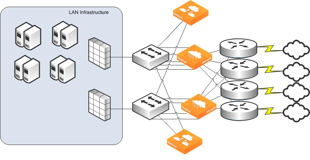
Figure: Interceptor octal deployment shows that if one of the Layer-3 LAN clouds failed, the only remaining available path is through the unaffected serial pair of Interceptors. To support this type of scenario, you can consider using the
interceptor communication allow-failure enable command similar to how you use the command in a parallel deployment. The corresponding command for the SteelHead is
steelhead communication allow-failure.
Compared to a parallel deployment, an Interceptor failure in an octal deployment doesn’t cause traffic routing or switching patterns to change, and it continues to allow traffic optimization.
We recommend that you use the debug validate deployment command when you configure an octal deployment. This command verifies that all devices in the cluster are appropriately configured with each other’s information.
Interceptor octal deployment
1. Connect to SteelHead 1 and enter the following commands:
interface inpath0_0 ip address 172.16.0.10 /24
ip in-path-gateway inpath0_0 172.16.0.1
interface inpath0_1 ip address 172.17.0.10 /24
ip in-path-gateway inpath0_1 172.17.0.1
in-path simplified routing "none"
in-path enable
in-path oop enable
steelhead communication enable
steelhead communication multi-interface enable
steelhead name int1 main-ip 172.16.41.2
steelhead name int1 additional-ip 172.16.42.2
steelhead name int2 main-ip 172.16.41.3
steelhead name int2 additional-ip 172.16.42.3
steelhead name int3 main-ip 172.16.43.2
steelhead name int3 additional-ip 172.16.44.2
steelhead name int4 main-ip 172.16.43.3
steelhead name int4 additional-ip 172.16.44.3
steelhead name int5 main-ip 172.16.45.2
steelhead name int5 additional-ip 172.16.46.2
steelhead name int6 main-ip 172.16.45.3
steelhead name int6 additional-ip 172.16.46.3
steelhead name int7 main-ip 172.16.47.2
steelhead name int7 additional-ip 172.16.48.2
steelhead name int8 main-ip 172.16.47.3
steelhead name int8 additional-ip 172.16.48.3
2. Connect to SteelHead 2 and enter the following commands:
interface inpath0_0 ip address 172.18.0.10 /24
ip in-path-gateway inpath0_0 172.18.0.1
interface inpath0_1 ip address 172.19.0.10 /24
ip in-path-gateway inpath0_1 172.19.0.1
in-path simplified routing "none"
in-path enable
in-path oop enable
steelhead communication enable
steelhead communication multi-interface enable
steelhead name int1 main-ip 172.16.41.2
steelhead name int1 additional-ip 172.16.42.2
steelhead name int2 main-ip 172.16.41.3
steelhead name int2 additional-ip 172.16.42.3
steelhead name int3 main-ip 172.16.43.2
steelhead name int3 additional-ip 172.16.44.2
steelhead name int4 main-ip 172.16.43.3
steelhead name int4 additional-ip 172.16.44.3
steelhead name int5 main-ip 172.16.45.2
steelhead name int5 additional-ip 172.16.46.2
steelhead name int6 main-ip 172.16.45.3
steelhead name int6 additional-ip 172.16.46.3
steelhead name int7 main-ip 172.16.47.2
steelhead name int7 additional-ip 172.16.48.2
steelhead name int8 main-ip 172.16.47.3
steelhead name int8 additional-ip 172.16.48.3
3. Connect to Interceptor 1 and enter the following commands:
interface inpath0_0 ip address 172.16.41.2 /24
in-path interface inpath0_0 enable
ip in-path-gateway inpath0_0 172.16.41.1
ip in-path route inpath0_0 172.16.42.0 255.255.255.0 172.16.41.4
ip in-path route inpath0_0 172.16.43.0 255.255.255.0 172.16.41.4
ip in-path route inpath0_0 172.16.44.0 255.255.255.0 172.16.41.4
ip in-path route inpath0_0 172.16.45.0 255.255.255.0 172.16.41.4
ip in-path route inpath0_0 172.16.46.0 255.255.255.0 172.16.41.4
ip in-path route inpath0_0 172.16.47.0 255.255.255.0 172.16.41.4
ip in-path route inpath0_0 172.16.48.0 255.255.255.0 172.16.41.4
ip in-path route inpath0_0 172.16.0.0 255.255.255.0 172.16.41.4
ip in-path route inpath0_0 172.17.0.0 255.255.255.0 172.16.41.4
ip in-path route inpath0_0 172.18.0.0 255.255.255.0 172.16.41.4
ip in-path route inpath0_0 172.19.0.0 255.255.255.0 172.16.41.4
interface inpath0_1 ip address 172.16.42.2 /24
in-path interface inpath0_1 enable
ip in-path-gateway inpath0_1 172.16.42.1
ip in-path route inpath0_0 172.16.41.0 255.255.255.0 172.16.42.4
ip in-path route inpath0_1 172.16.43.0 255.255.255.0 172.16.42.4
ip in-path route inpath0_1 172.16.44.0 255.255.255.0 172.16.42.4
ip in-path route inpath0_1 172.16.45.0 255.255.255.0 172.16.42.4
ip in-path route inpath0_1 172.16.46.0 255.255.255.0 172.16.42.4
ip in-path route inpath0_1 172.16.47.0 255.255.255.0 172.16.42.4
ip in-path route inpath0_1 172.16.48.0 255.255.255.0 172.16.42.4
ip in-path route inpath0_1 172.16.0.0 255.255.255.0 172.16.42.4
ip in-path route inpath0_1 172.17.0.0 255.255.255.0 172.16.42.4
ip in-path route inpath0_1 172.18.0.0 255.255.255.0 172.16.42.4
ip in-path route inpath0_1 172.19.0.0 255.255.255.0 172.16.42.4
interceptor communication multi-interface enable
failover steelhead interceptor name int2 main-ip 172.16.41.3
failover steelhead interceptor name int2 additional-ip 172.16.42.3
steelhead interceptor name int3 main-ip 172.16.43.2
steelhead interceptor name int3 additional-ip 172.16.44.2
steelhead interceptor name int4 main-ip 172.16.43.3
steelhead interceptor name int4 additional-ip 172.16.44.3
steelhead interceptor name int5 main-ip 172.16.45.2
steelhead interceptor name int5 additional-ip 172.16.46.2
steelhead interceptor name int6 main-ip 172.16.45.3
steelhead interceptor name int6 additional-ip 172.16.46.3
steelhead interceptor name int7 main-ip 172.16.47.2
steelhead interceptor name int7 additional-ip 172.16.48.2
steelhead interceptor name int8 main-ip 172.16.47.3
steelhead interceptor name int8 additional-ip 172.16.48.3
steelhead communication multi-interface enable
steelhead name steelhead1 main-ip 172.16.0.10
steelhead name steelhead1 additional-ip 172.17.0.10
steelhead name steelhead2 main-ip 172.18.0.10
steelhead name steelhead2 additional-ip 172.19.0.10
4. Connect to Interceptor 2 and enter the following commands:
interface inpath0_0 ip address 172.16.41.3 /24
in-path interface inpath0_0 enable
ip in-path-gateway inpath0_0 172.16.41.1
ip in-path route inpath0_0 172.16.42.0 255.255.255.0 172.16.41.4
ip in-path route inpath0_0 172.16.43.0 255.255.255.0 172.16.41.4
ip in-path route inpath0_0 172.16.44.0 255.255.255.0 172.16.41.4
ip in-path route inpath0_0 172.16.45.0 255.255.255.0 172.16.41.4
ip in-path route inpath0_0 172.16.46.0 255.255.255.0 172.16.41.4
ip in-path route inpath0_0 172.16.47.0 255.255.255.0 172.16.41.4
ip in-path route inpath0_0 172.16.48.0 255.255.255.0 172.16.41.4
ip in-path route inpath0_0 172.16.0.0 255.255.255.0 172.16.41.4
ip in-path route inpath0_0 172.17.0.0 255.255.255.0 172.16.41.4
ip in-path route inpath0_0 172.18.0.0 255.255.255.0 172.16.41.4
ip in-path route inpath0_0 172.19.0.0 255.255.255.0 172.16.41.4
interface inpath0_1 ip address 172.16.42.3 /24
in-path interface inpath0_1 enable
ip in-path-gateway inpath0_1 172.16.42.1
ip in-path route inpath0_0 172.16.41.0 255.255.255.0 172.16.42.4
ip in-path route inpath0_1 172.16.43.0 255.255.255.0 172.16.42.4
ip in-path route inpath0_1 172.16.44.0 255.255.255.0 172.16.42.4
ip in-path route inpath0_1 172.16.45.0 255.255.255.0 172.16.42.4
ip in-path route inpath0_1 172.16.46.0 255.255.255.0 172.16.42.4
ip in-path route inpath0_1 172.16.47.0 255.255.255.0 172.16.42.4
ip in-path route inpath0_1 172.16.48.0 255.255.255.0 172.16.42.4
ip in-path route inpath0_1 172.16.0.0 255.255.255.0 172.16.42.4
ip in-path route inpath0_1 172.17.0.0 255.255.255.0 172.16.42.4
ip in-path route inpath0_1 172.18.0.0 255.255.255.0 172.16.42.4
ip in-path route inpath0_1 172.19.0.0 255.255.255.0 172.16.42.4
interceptor communication multi-interface enable
failover steelhead interceptor name int1 main-ip 172.16.41.2
failover steelhead interceptor name int1 additional-ip 172.16.42.2
steelhead interceptor name int3 main-ip 172.16.43.2
steelhead interceptor name int3 additional-ip 172.16.44.2
steelhead interceptor name int4 main-ip 172.16.43.3
steelhead interceptor name int4 additional-ip 172.16.44.3
steelhead interceptor name int5 main-ip 172.16.45.2
steelhead interceptor name int5 additional-ip 172.16.46.2
steelhead interceptor name int6 main-ip 172.16.45.3
steelhead interceptor name int6 additional-ip 172.16.46.3
steelhead interceptor name int7 main-ip 172.16.47.2
steelhead interceptor name int7 additional-ip 172.16.48.2
steelhead interceptor name int8 main-ip 172.16.47.3
steelhead interceptor name int8 additional-ip 172.16.48.3
steelhead communication multi-interface enable
steelhead name steelhead1 main-ip 172.16.0.10
steelhead name steelhead1 additional-ip 172.17.0.10
steelhead name steelhead2 main-ip 172.18.0.10
steelhead name steelhead2 additional-ip 172.19.0.10
5. Connect to Interceptor 3 and enter the following commands:
interface inpath0_0 ip address 172.16.43.2 /24
in-path interface inpath0_0 enable
ip in-path-gateway inpath0_0 172.16.43.1
ip in-path route inpath0_0 172.16.41.0 255.255.255.0 172.16.43.4
ip in-path route inpath0_0 172.16.42.0 255.255.255.0 172.16.43.4
ip in-path route inpath0_0 172.16.44.0 255.255.255.0 172.16.43.4
ip in-path route inpath0_0 172.16.45.0 255.255.255.0 172.16.43.4
ip in-path route inpath0_0 172.16.46.0 255.255.255.0 172.16.43.4
ip in-path route inpath0_0 172.16.47.0 255.255.255.0 172.16.43.4
ip in-path route inpath0_0 172.16.48.0 255.255.255.0 172.16.43.4
ip in-path route inpath0_0 172.16.0.0 255.255.255.0 172.16.43.4
ip in-path route inpath0_0 172.17.0.0 255.255.255.0 172.16.43.4
ip in-path route inpath0_0 172.18.0.0 255.255.255.0 172.16.43.4
ip in-path route inpath0_0 172.19.0.0 255.255.255.0 172.16.43.4
interface inpath0_1 ip address 172.16.44.2 /24
in-path interface inpath0_1 enable
ip in-path-gateway inpath0_1 172.16.44.1
ip in-path route inpath0_1 172.16.41.0 255.255.255.0 172.16.44.4
ip in-path route inpath0_1 172.16.42.0 255.255.255.0 172.16.44.4
ip in-path route inpath0_0 172.16.43.0 255.255.255.0 172.16.44.4
ip in-path route inpath0_1 172.16.45.0 255.255.255.0 172.16.44.4
ip in-path route inpath0_1 172.16.46.0 255.255.255.0 172.16.44.4
ip in-path route inpath0_1 172.16.47.0 255.255.255.0 172.16.44.4
ip in-path route inpath0_1 172.16.48.0 255.255.255.0 172.16.44.4
ip in-path route inpath0_1 172.16.0.0 255.255.255.0 172.16.44.4
ip in-path route inpath0_1 172.17.0.0 255.255.255.0 172.16.44.4
ip in-path route inpath0_1 172.18.0.0 255.255.255.0 172.16.44.4
ip in-path route inpath0_1 172.19.0.0 255.255.255.0 172.16.44.4
interceptor communication multi-interface enable
failover steelhead interceptor name int4 main-ip 172.16.43.3
failover steelhead interceptor name int4 additional-ip 172.16.44.3
steelhead interceptor name int1 main-ip 172.16.41.2
steelhead interceptor name int1 additional-ip 172.16.42.2
steelhead interceptor name int2 main-ip 172.16.41.3
steelhead interceptor name int2 additional-ip 172.16.42.3
steelhead interceptor name int5 main-ip 172.16.45.2
steelhead interceptor name int5 additional-ip 172.16.46.2
steelhead interceptor name int6 main-ip 172.16.45.3
steelhead interceptor name int6 additional-ip 172.16.46.3
steelhead interceptor name int7 main-ip 172.16.47.2
steelhead interceptor name int7 additional-ip 172.16.48.2
steelhead interceptor name int8 main-ip 172.16.47.3
steelhead interceptor name int8 additional-ip 172.16.48.3
steelhead communication multi-interface enable
steelhead name steelhead1 main-ip 172.16.0.10
steelhead name steelhead1 additional-ip 172.17.0.10
steelhead name steelhead2 main-ip 172.18.0.10
steelhead name steelhead2 additional-ip 172.19.0.10
6. Connect to Interceptor 4 and enter the following commands:
interface inpath0_0 ip address 172.16.43.3 /24
in-path interface inpath0_0 enable
ip in-path-gateway inpath0_0 172.16.43.1
ip in-path route inpath0_0 172.16.41.0 255.255.255.0 172.16.43.4
ip in-path route inpath0_0 172.16.42.0 255.255.255.0 172.16.43.4
ip in-path route inpath0_0 172.16.44.0 255.255.255.0 172.16.43.4
ip in-path route inpath0_0 172.16.45.0 255.255.255.0 172.16.43.4
ip in-path route inpath0_0 172.16.46.0 255.255.255.0 172.16.43.4
ip in-path route inpath0_0 172.16.47.0 255.255.255.0 172.16.43.4
ip in-path route inpath0_0 172.16.48.0 255.255.255.0 172.16.43.4
ip in-path route inpath0_0 172.16.0.0 255.255.255.0 172.16.43.4
ip in-path route inpath0_0 172.17.0.0 255.255.255.0 172.16.43.4
ip in-path route inpath0_0 172.18.0.0 255.255.255.0 172.16.43.4
ip in-path route inpath0_0 172.19.0.0 255.255.255.0 172.16.43.4
interface inpath0_1 ip address 172.16.44.3 /24
in-path interface inpath0_1 enable
ip in-path-gateway inpath0_1 172.16.44.1
ip in-path route inpath0_1 172.16.41.0 255.255.255.0 172.16.44.4
ip in-path route inpath0_1 172.16.42.0 255.255.255.0 172.16.44.4
ip in-path route inpath0_0 172.16.43.0 255.255.255.0 172.16.44.4
ip in-path route inpath0_1 172.16.45.0 255.255.255.0 172.16.44.4
ip in-path route inpath0_1 172.16.46.0 255.255.255.0 172.16.44.4
ip in-path route inpath0_1 172.16.47.0 255.255.255.0 172.16.44.4
ip in-path route inpath0_1 172.16.48.0 255.255.255.0 172.16.44.4
ip in-path route inpath0_1 172.16.0.0 255.255.255.0 172.16.44.4
ip in-path route inpath0_1 172.17.0.0 255.255.255.0 172.16.44.4
ip in-path route inpath0_1 172.18.0.0 255.255.255.0 172.16.44.4
ip in-path route inpath0_1 172.19.0.0 255.255.255.0 172.16.44.4
interceptor communication multi-interface enable
failover steelhead interceptor name int3 main-ip 172.16.43.2
failover steelhead interceptor name int3 additional-ip 172.16.44.2
steelhead interceptor name int1 main-ip 172.16.41.2
steelhead interceptor name int1 additional-ip 172.16.42.2
steelhead interceptor name int2 main-ip 172.16.41.3
steelhead interceptor name int2 additional-ip 172.16.42.3
steelhead interceptor name int5 main-ip 172.16.45.2
steelhead interceptor name int5 additional-ip 172.16.46.2
steelhead interceptor name int6 main-ip 172.16.45.3
steelhead interceptor name int6 additional-ip 172.16.46.3
steelhead interceptor name int7 main-ip 172.16.47.2
steelhead interceptor name int7 additional-ip 172.16.48.2
steelhead interceptor name int8 main-ip 172.16.47.3
steelhead interceptor name int8 additional-ip 172.16.48.3
steelhead communication multi-interface enable
steelhead name steelhead1 main-ip 172.16.0.10
steelhead name steelhead1 additional-ip 172.17.0.10
steelhead name steelhead2 main-ip 172.18.0.10
steelhead name steelhead2 additional-ip 172.19.0.10
7. Connect to Interceptor 5 and enter the following commands:
interface inpath0_0 ip address 172.16.45.2 /24
in-path interface inpath0_0 enable
ip in-path-gateway inpath0_0 172.16.45.1
ip in-path route inpath0_0 172.16.41.0 255.255.255.0 172.16.45.4
ip in-path route inpath0_0 172.16.42.0 255.255.255.0 172.16.45.4
ip in-path route inpath0_0 172.16.43.0 255.255.255.0 172.16.45.4
ip in-path route inpath0_0 172.16.44.0 255.255.255.0 172.16.45.4
ip in-path route inpath0_0 172.16.46.0 255.255.255.0 172.16.45.4
ip in-path route inpath0_0 172.16.47.0 255.255.255.0 172.16.45.4
ip in-path route inpath0_0 172.16.48.0 255.255.255.0 172.16.45.4
ip in-path route inpath0_0 172.16.0.0 255.255.255.0 172.16.45.4
ip in-path route inpath0_0 172.17.0.0 255.255.255.0 172.16.45.4
ip in-path route inpath0_0 172.18.0.0 255.255.255.0 172.16.45.4
ip in-path route inpath0_0 172.19.0.0 255.255.255.0 172.16.45.4
interface inpath0_1 ip address 172.16.46.2 /24
in-path interface inpath0_1 enable
ip in-path-gateway inpath0_1 172.16.46.1
ip in-path route inpath0_1 172.16.41.0 255.255.255.0 172.16.46.4
ip in-path route inpath0_1 172.16.42.0 255.255.255.0 172.16.46.4
ip in-path route inpath0_1 172.16.43.0 255.255.255.0 172.16.46.4
ip in-path route inpath0_1 172.16.44.0 255.255.255.0 172.16.46.4
ip in-path route inpath0_0 172.16.45.0 255.255.255.0 172.16.46.4
ip in-path route inpath0_1 172.16.47.0 255.255.255.0 172.16.46.4
ip in-path route inpath0_1 172.16.48.0 255.255.255.0 172.16.46.4
ip in-path route inpath0_1 172.16.0.0 255.255.255.0 172.16.46.4
ip in-path route inpath0_1 172.17.0.0 255.255.255.0 172.16.46.4
ip in-path route inpath0_1 172.18.0.0 255.255.255.0 172.16.46.4
ip in-path route inpath0_1 172.19.0.0 255.255.255.0 172.16.46.4
interceptor communication multi-interface enable
failover steelhead interceptor name int6 main-ip 172.16.45.3
failover steelhead interceptor name int6 additional-ip 172.16.46.3
steelhead interceptor name int1 main-ip 172.16.41.2
steelhead interceptor name int1 additional-ip 172.16.42.2
steelhead interceptor name int2 main-ip 172.16.41.3
steelhead interceptor name int2 additional-ip 172.16.42.3
steelhead interceptor name int3 main-ip 172.16.43.2
steelhead interceptor name int3 additional-ip 172.16.44.2
steelhead interceptor name int4 main-ip 172.16.43.3
steelhead interceptor name int4 additional-ip 172.16.44.3
steelhead interceptor name int7 main-ip 172.16.47.2
steelhead interceptor name int7 additional-ip 172.16.48.2
steelhead interceptor name int8 main-ip 172.16.47.3
steelhead interceptor name int8 additional-ip 172.16.48.3
steelhead communication multi-interface enable
steelhead name steelhead1 main-ip 172.16.0.10
steelhead name steelhead1 additional-ip 172.17.0.10
steelhead name steelhead2 main-ip 172.18.0.10
steelhead name steelhead2 additional-ip 172.19.0.10
8. Connect to Interceptor 6 and enter the following commands:
interface inpath0_0 ip address 172.16.45.3 /24
in-path interface inpath0_0 enable
ip in-path-gateway inpath0_0 172.16.45.1
ip in-path route inpath0_0 172.16.41.0 255.255.255.0 172.16.45.4
ip in-path route inpath0_0 172.16.42.0 255.255.255.0 172.16.45.4
ip in-path route inpath0_0 172.16.43.0 255.255.255.0 172.16.45.4
ip in-path route inpath0_0 172.16.44.0 255.255.255.0 172.16.45.4
ip in-path route inpath0_0 172.16.46.0 255.255.255.0 172.16.45.4
ip in-path route inpath0_0 172.16.47.0 255.255.255.0 172.16.45.4
ip in-path route inpath0_0 172.16.48.0 255.255.255.0 172.16.45.4
ip in-path route inpath0_0 172.16.0.0 255.255.255.0 172.16.45.4
ip in-path route inpath0_0 172.17.0.0 255.255.255.0 172.16.45.4
ip in-path route inpath0_0 172.18.0.0 255.255.255.0 172.16.45.4
ip in-path route inpath0_0 172.19.0.0 255.255.255.0 172.16.45.4
interface inpath0_1 ip address 172.16.46.3 /24
in-path interface inpath0_1 enable
ip in-path-gateway inpath0_1 172.16.46.1
ip in-path route inpath0_1 172.16.41.0 255.255.255.0 172.16.46.4
ip in-path route inpath0_1 172.16.42.0 255.255.255.0 172.16.46.4
ip in-path route inpath0_1 172.16.43.0 255.255.255.0 172.16.46.4
ip in-path route inpath0_1 172.16.44.0 255.255.255.0 172.16.46.4
ip in-path route inpath0_0 172.16.45.0 255.255.255.0 172.16.46.4
ip in-path route inpath0_1 172.16.47.0 255.255.255.0 172.16.46.4
ip in-path route inpath0_1 172.16.48.0 255.255.255.0 172.16.46.4
ip in-path route inpath0_1 172.16.0.0 255.255.255.0 172.16.46.4
ip in-path route inpath0_1 172.17.0.0 255.255.255.0 172.16.46.4
ip in-path route inpath0_1 172.18.0.0 255.255.255.0 172.16.46.4
ip in-path route inpath0_1 172.19.0.0 255.255.255.0 172.16.46.4
interceptor communication multi-interface enable
failover steelhead interceptor name int5 main-ip 172.16.45.2
failover steelhead interceptor name int5 additional-ip 172.16.46.2
steelhead interceptor name int1 main-ip 172.16.41.2
steelhead interceptor name int1 additional-ip 172.16.42.2
steelhead interceptor name int2 main-ip 172.16.41.3
steelhead interceptor name int2 additional-ip 172.16.42.3
steelhead interceptor name int3 main-ip 172.16.43.2
steelhead interceptor name int3 additional-ip 172.16.44.2
steelhead interceptor name int4 main-ip 172.16.43.3
steelhead interceptor name int4 additional-ip 172.16.44.3
steelhead interceptor name int7 main-ip 172.16.47.2
steelhead interceptor name int7 additional-ip 172.16.48.2
steelhead interceptor name int8 main-ip 172.16.47.3
steelhead interceptor name int8 additional-ip 172.16.48.3
steelhead communication multi-interface enable
steelhead name steelhead1 main-ip 172.16.0.10
steelhead name steelhead1 additional-ip 172.17.0.10
steelhead name steelhead2 main-ip 172.18.0.10
steelhead name steelhead2 additional-ip 172.19.0.10
9. Connect to Interceptor 7 and enter the following commands:
interface inpath0_0 ip address 172.16.47.2 /24
in-path interface inpath0_0 enable
ip in-path-gateway inpath0_0 172.16.47.1
ip in-path route inpath0_0 172.16.41.0 255.255.255.0 172.16.47.4
ip in-path route inpath0_0 172.16.42.0 255.255.255.0 172.16.47.4
ip in-path route inpath0_0 172.16.43.0 255.255.255.0 172.16.47.4
ip in-path route inpath0_0 172.16.44.0 255.255.255.0 172.16.47.4
ip in-path route inpath0_0 172.16.45.0 255.255.255.0 172.16.47.4
ip in-path route inpath0_0 172.16.46.0 255.255.255.0 172.16.47.4
ip in-path route inpath0_0 172.16.48.0 255.255.255.0 172.16.47.4
ip in-path route inpath0_0 172.16.0.0 255.255.255.0 172.16.47.4
ip in-path route inpath0_0 172.17.0.0 255.255.255.0 172.16.47.4
ip in-path route inpath0_0 172.18.0.0 255.255.255.0 172.16.47.4
ip in-path route inpath0_0 172.19.0.0 255.255.255.0 172.16.47.4
interface inpath0_1 ip address 172.16.48.2 /24
in-path interface inpath0_1 enable
ip in-path-gateway inpath0_1 172.16.48.1
ip in-path route inpath0_1 172.16.41.0 255.255.255.0 172.16.48.4
ip in-path route inpath0_1 172.16.42.0 255.255.255.0 172.16.48.4
ip in-path route inpath0_1 172.16.43.0 255.255.255.0 172.16.48.4
ip in-path route inpath0_1 172.16.44.0 255.255.255.0 172.16.48.4
ip in-path route inpath0_1 172.16.45.0 255.255.255.0 172.16.48.4
ip in-path route inpath0_1 172.16.46.0 255.255.255.0 172.16.48.4
ip in-path route inpath0_0 172.16.47.0 255.255.255.0 172.16.48.4
ip in-path route inpath0_1 172.16.0.0 255.255.255.0 172.16.48.4
ip in-path route inpath0_1 172.17.0.0 255.255.255.0 172.16.48.4
ip in-path route inpath0_1 172.18.0.0 255.255.255.0 172.16.48.4
ip in-path route inpath0_1 172.19.0.0 255.255.255.0 172.16.48.4
interceptor communication multi-interface enable
failover steelhead interceptor name int8 main-ip 172.16.47.3
failover steelhead interceptor name int8 additional-ip 172.16.48.3
steelhead interceptor name int1 main-ip 172.16.41.2
steelhead interceptor name int1 additional-ip 172.16.42.2
steelhead interceptor name int2 main-ip 172.16.41.3
steelhead interceptor name int2 additional-ip 172.16.42.3
steelhead interceptor name int3 main-ip 172.16.43.2
steelhead interceptor name int3 additional-ip 172.16.44.2
steelhead interceptor name int4 main-ip 172.16.43.3
steelhead interceptor name int4 additional-ip 172.16.44.3
steelhead interceptor name int5 main-ip 172.16.45.2
steelhead interceptor name int5 additional-ip 172.16.46.2
steelhead interceptor name int6 main-ip 172.16.45.3
steelhead interceptor name int6 additional-ip 172.16.46.3
steelhead communication multi-interface enable
steelhead name steelhead1 main-ip 172.16.0.10
steelhead name steelhead1 additional-ip 172.17.0.10
steelhead name steelhead2 main-ip 172.18.0.10
steelhead name steelhead2 additional-ip 172.19.0.10
10. Connect to Interceptor 8 and enter the following commands:
interface inpath0_0 ip address 172.16.47.3 /24
in-path interface inpath0_0 enable
ip in-path-gateway inpath0_0 172.16.47.1
ip in-path route inpath0_0 172.16.41.0 255.255.255.0 172.16.47.4
ip in-path route inpath0_0 172.16.42.0 255.255.255.0 172.16.47.4
ip in-path route inpath0_0 172.16.43.0 255.255.255.0 172.16.47.4
ip in-path route inpath0_0 172.16.44.0 255.255.255.0 172.16.47.4
ip in-path route inpath0_0 172.16.45.0 255.255.255.0 172.16.47.4
ip in-path route inpath0_0 172.16.46.0 255.255.255.0 172.16.47.4
ip in-path route inpath0_0 172.16.48.0 255.255.255.0 172.16.47.4
ip in-path route inpath0_0 172.16.0.0 255.255.255.0 172.16.47.4
ip in-path route inpath0_0 172.17.0.0 255.255.255.0 172.16.47.4
ip in-path route inpath0_0 172.18.0.0 255.255.255.0 172.16.47.4
ip in-path route inpath0_0 172.19.0.0 255.255.255.0 172.16.47.4
interface inpath0_1 ip address 172.16.48.3 /24
in-path interface inpath0_1 enable
ip in-path-gateway inpath0_1 172.16.48.1
ip in-path route inpath0_1 172.16.41.0 255.255.255.0 172.16.48.4
ip in-path route inpath0_1 172.16.42.0 255.255.255.0 172.16.48.4
ip in-path route inpath0_1 172.16.43.0 255.255.255.0 172.16.48.4
ip in-path route inpath0_1 172.16.44.0 255.255.255.0 172.16.48.4
ip in-path route inpath0_1 172.16.45.0 255.255.255.0 172.16.48.4
ip in-path route inpath0_1 172.16.46.0 255.255.255.0 172.16.48.4
ip in-path route inpath0_0 172.16.47.0 255.255.255.0 172.16.48.4
ip in-path route inpath0_1 172.16.0.0 255.255.255.0 172.16.48.4
ip in-path route inpath0_1 172.17.0.0 255.255.255.0 172.16.48.4
ip in-path route inpath0_1 172.18.0.0 255.255.255.0 172.16.48.4
ip in-path route inpath0_1 172.19.0.0 255.255.255.0 172.16.48.4
interceptor communication multi-interface enable
failover steelhead interceptor name int7 main-ip 172.16.47.2
failover steelhead interceptor name int7 additional-ip 172.16.48.2
steelhead interceptor name int1 main-ip 172.16.41.2
steelhead interceptor name int1 additional-ip 172.16.42.2
steelhead interceptor name int2 main-ip 172.16.41.3
steelhead interceptor name int2 additional-ip 172.16.42.3
steelhead interceptor name int3 main-ip 172.16.43.2
steelhead interceptor name int3 additional-ip 172.16.44.2
steelhead interceptor name int4 main-ip 172.16.43.3
steelhead interceptor name int4 additional-ip 172.16.44.3
steelhead interceptor name int5 main-ip 172.16.45.2
steelhead interceptor name int5 additional-ip 172.16.46.2
steelhead interceptor name int6 main-ip 172.16.45.3
steelhead interceptor name int6 additional-ip 172.16.46.3
steelhead communication multi-interface enable
steelhead name steelhead1 main-ip 172.16.0.10
steelhead name steelhead1 additional-ip 172.17.0.10
steelhead name steelhead2 main-ip 172.18.0.10
steelhead name steelhead2 additional-ip 172.19.0.10
Deploying a virtual in-path Interceptor cluster
In a virtual in-path Interceptor cluster, you install two or more Interceptors in a cluster as neighbor Interceptors rather than failover Interceptors. Configure each Interceptor as a neighbor for the others and enable the interceptor communication allow-failure enable command. Unlike physical in-path clusters, virtual in-path clusters rely on the redirecting network device to determine failover to remaining Interceptors. For instance, Interceptors deployed with WCCP have the same time-out period of up to 30 seconds before a router recognizes an Interceptor failure.
In a virtual in-path SteelHead cluster, you must plan carefully to determine what traffic is redirected to the SteelHeads. You must often use mask assignment or multiple service groups with WCCP, and you can use multiple next hops and different permit sequences with PBR. The main advantage of using virtual in-path Interceptors instead of direct virtual in-path SteelHeads is that the Interceptor intelligent load-balancing algorithms are still used to determine SteelHead redirection. It isn’t as critical to plan which Interceptor receives what traffic, because all Interceptors in the cluster exchange information and redirect consistently to the SteelHeads.
Virtual in-path Interceptor cluster deployment
1. Connect to SteelHead 1 and enter the following commands:
interface inpath0_0 ip address 10.1.0.20 /24
ip in-path-gateway inpath0_0 10.1.0.1
in-path enable
in-path oop enable
steelhead communication enable
steelhead communication multi-interface enable
steelhead communication allow-failure
steelhead name interceptor1 main-ip 10.1.0.6
steelhead name interceptor2 main-ip 10.1.0.7
2. Connect to SteelHead 2 and enter the following commands:
interface inpath0_0 ip address 10.1.0.21 /24
ip in-path-gateway inpath0_0 10.1.0.1
in-path enable
in-path oop enable
steelhead communication enable
steelhead communication multi-interface enable
steelhead communication allow-failure
steelhead name interceptor1 main-ip 10.1.0.6
steelhead name interceptor2 main-ip 10.1.0.7
3. Connect to Interceptor 1 and enter the following commands:
in-path oop enable
interface inpath0_0 ip address 10.1.0.6 /24
in-path interface inpath0_0 enable
Interceptor
no interface inpath0_0 fail-to-bypass enable
ip in-path-gateway inpath0_0 10.1.0.1
interceptor communication allow-failure enable
interceptor communication multi-interface enable
interceptor name interceptor2 main-ip 10.1.0.7
steelhead communication allow-failure
steelhead communication multi-interface enable
steelhead name steelhead1 main-ip 10.1.0.20
steelhead name steelhead2 main-ip 10.1.0.21
4. Connect to Interceptor 2 and enter the following commands:
in-path oop enable
interface inpath0_0 ip address 10.1.0.7 /24
in-path interface inpath0_0 enable
Interceptor
no interface inpath0_0 fail-to-bypass enable
ip in-path-gateway inpath0_0 10.1.0.1
interceptor communication allow-failure enable
interceptor communication multi-interface enable
interceptor name interceptor1 main-ip 10.1.0.6
steelhead communication allow-failure
steelhead communication multi-interface enable
steelhead name steelhead1 main-ip 10.1.0.20
steelhead name steelhead2 main-ip 10.1.0.21
Choosing a cluster type
You can choose a cluster type depending on the:
n location and number of links to the WAN.
n amount of data flowing on the links to the WAN.
n desired path of data during failures.
n physical in-line devices that are allowed.
Series deployments provide single failure redundancy. In dual failures, traffic continues to flow to the WAN on the original network path. Series deployments can’t be used when:
n there are more in-path links that can be covered with a single Interceptor.
n the links to the WAN aren’t located at the same site.
n the total data traversing through the Interceptor (excluding data passing through using hardware-assisted pass-through) exceeds the specifications of the Interceptor model.
Parallel with fail-to-block deployments also provide single failure redundancy and are used when there are more in-path links than can be covered with a single Interceptor. If the data traversing through all of the links to the WAN exceed the specifications of a single Interceptor model, then you can use a parallel with fail-to-block deployment to reduce the amount of data any single Interceptor would process during normal operation. When an Interceptor fails, these deployments alter the path of data in the network and cause remaining Interceptors and links to process all of the data to the WAN.
Quad deployments provide single Interceptor failure redundancy. Dual Interceptor failure redundancy is possible if the failed Interceptors aren’t failover peers. If you configure the Interceptors as failover peers, then a path to the WAN doesn’t have redirection coverage. In this case, the asymmetric route detection of the SteelHead still functions, but for some asymmetric flows, the SteelHeads recognize asymmetry due to initial application connection failures. In any single Interceptor failure scenario, all flows continue to be optimized, and new connections continue to go through autodiscovery. A single Interceptor failure doesn’t cause the alteration of the path of data to the WAN.
For most physical in-path deployments, we recommend series deployments. If there are too many WAN links for a series deployment, we recommend quad deployment. The quad deployment handles failure more efficiently than the parallel with the fail-to-block option, both for single and double Interceptor failures.
You can deploy virtual in-path deployments for data center environments in which you can’t have or don’t want physical in-line devices, but you need SteelHead-aware load balancing. For most environments, physical in-path deployments are recommended.
Connection forwarding settings for allow-failure
In an Interceptor topology, the Interceptors communicate with other Interceptors and SteelHeads, while the SteelHeads communicate with only the Interceptors. Load-balancing rules govern the communication between the Interceptor and SteelHead. You don’t need to configure a specific CLI command: allow-failure or no allow-failure.
The following table shows the Interceptor and SteelHead connection forwarding settings for allow-failure given an Interceptor topology.
| Interceptor CLI commands | SteelHead CLI commands |
Deployment type | Interceptor-Interceptor | Connection forwarding |
Single Interceptor | no interceptor communication allow-failure enable | no in-path neighbor allow-failure |
Serial Interceptors | no interceptor communication allow-failure enable | no in-path neighbor allow-failure |
Parallel Interceptors, fail-to-block | interceptor communication allow-failure enable | in-path neighbor allow-failure |
Parallel Interceptors, fail-to-wire | no interceptor communication allow-failure enable | no in-path neighbor allow-failure |
Quad and Octal Interceptors | no interceptor communication allow-failure enable | no in-path neighbor allow-failure |
Virtual in-path Interceptors | interceptor communication allow-failure enable | in-path neighbor allow-failure |
You don’t need to enter default commands into the Interceptor and SteelHead. The default command for an Interceptor is no interceptor communication allow-failure enable, and the default SteelHead command is no in-path neighbor allow-failure.