Replacing a Virtual Edge Appliance
This chapter describes how to replace a SteelFusion Virtual Edge in the case of an unexpected appliance or remote site failure. It includes the following sections:
Overview
The Virtual Edge appliance is installed on off-the-shelf hardware by system integrators. In the event of a catastrophic failure, you may need to replace the Virtual Edge appliance and remap the LUNs.
Note: The blockstore is a part of Virtual Edge. If you replace the Virtual Edge, the cached data on the failed blockstore is discarded. To protect the Virtual Edge against a single point of failure, consider an HA deployment of Virtual Edge.
At a high level, there are two steps to replacing a Virtual Edge appliance:
1. Replace the hardware and deploy the Virtual Edge. This process is discussed in this chapter.
2. Follow the steps in the “Edge replacement” section of SteelFusion Design Guide, where details are provided for configuring the Virtual Edge and remapping the LUNs.
Basic steps for replacing a Virtual Edge appliance
This section provides an overview of the basic steps to replace the Virtual Edge appliance hardware. For the detailed ESXi and Virtual Edge installation procedure, see
ESXi and Virtual Edge installation.
The workflow requires that you work closely with the system integrator, and that they guide you through the recovery procedure.
1. Receive the RMA USB device or image from the system integrator. If you have received an image, see
Creating the RMA USB device for details on what to do next.
2. Configure the new Virtual Edge appliance following the procedure in
Appliance hardware BIOS configuration. Note that the PXE boot configuration steps in this section are not required. The system integrator will assist you with this procedure.
3. Insert the RMA USB device into the appliance and power it on.
4. Press F11 to invoke the boot menu and select the attached USB device to boot. The vSphere ESXi hypervisor installs automatically on booting from the USB device.
5. Trigger the Virtual Edge deploy script to deploy the baseline version of Virtual Edge.
7. Power on the vSFED VM.
8. Configure Virtual Edge with the help of the system integrator.
9. Once Virtual Edge is configured, contact Riverbed Support to perform the steps in the “Edge Replacement” section of the SteelFusion Design Guide.
Appliance hardware BIOS configuration
The steps to configure the appliance hardware vary depending on the server vendor’s BIOS user interface. Usually, this configuration is performed when BIOS comes up. If you have any questions or issues, contact your hardware manufacturer. Your system integrator will assist you with this procedure.
To configure the appliance hardware
1. If your appliance has a master power switch, ensure that it is in the off position.
2. Plug the AC power cord into the appliance.
3. Plug the AC power cord into an uninterrupted AC power source.
4. Plug the straight-through cable into the primary port of the appliance and the LAN switch so that it is in the installation network.
The primary port can be any port on your LAN switch configured to connect to a host.
5. Using the appropriate hardware and software, connect to the console of the appliance.
6. Press the appliance power switch on and check the status lights.
7. Configure BIOS so that the disk for ESXi installation appears as first in the list.
ESXi kickstart installs ESXi using the command install --firstdisk —overwritevmfs.
8. Virtual Edge requires two RAID 1 or RAID 10 volumes. For details on volume sizes for your Virtual Edge model, contact your system integrator. Using the server vendor’s RAID configuration procedure, configure RAID volumes on the server hardware. Use two or more SSD drives to create a RAID 1/10 volume for the cache disks.
9. Use two or more HDDs or SSDs to create a RAID 1/10 volume for storing the blockstore.
The minimum size is the same as the HDD volume size.
10. Disable disk caching on the HDDs.
11. Set up the boot settings to boot using the first disk on which ESXi will get installed.
12. Save the changes to the BIOS configurations.
13. Power cycle the appliance.
Creating the RMA USB device
Once you receive the replacement appliance, you can create the RMA USB device.
If the system integrator shared the RMA image with you for download, they should also include the burn_rma_image utility to assist you in creating the RMA USB device. As a prerequisite, you should have a Linux box or VM in your environment with USB access enabled to burn the RMA Image onto a USB device.
Prerequisites
1. The USB memory module must be at least 4 GB.
2. The RMA USB device should be the only USB module attached on the appliance during the deployment procedure.
3. RMA installations are not supported over remote console, Intelligent Platform Management Interface (IPMI) console, or Kernel-based Virtual Machine (KVM) console. The RMA USB device must be physically attached to the appliance.
4. Do not interrupt or stop the installation process. Any user interruption in the RMA procedure time will require a reboot of the appliance and you will need to restart the procedure.
To create the RMA USB device
1. Download the necessary files from the location specified by the system integrator.
2. Copy the files to any Linux box or VM supporting Python version 2.6.x.
3. Attach the USB device to Linux box or VM.
4. Power on or reboot the appliance.
5. Run the utility. The utility requires the RMA USB image path and, optionally, the USB device to write to.
Note: If you do not specify the USB device, the tool lists the attached USB devices and prompts you to select the USB device to use.
$ ./burn_rma_image --help
usage: burn_rma_image [-h] -i IMAGE [-u USB]
Burn RMA image to USB disk.
optional arguments:
-h, --help show this help message and exit
-u USB, --usb USB USB disk path (i.e. /dev/sdb)
required arguments:
-i IMAGE, --image IMAGE
Path to RMA image file (i.e. RMA.img)
$ ./burn_rma_image -i rma_image
Following USB disks found:
1> /dev/sdd SMI Corporation USB DISK (4026MB)
Select the USB device [Q for quitting] : 1
Input RMA Image : usb-500GB
Output USB disk : /dev/sdd
Writing image to USB disk, All disk data will be erased.
Do you want to continue[Y/N]:y
Status: 100%
USB creation successful.
ESXi and Virtual Edge installation
The RMA USB device is a bootable USB that can image a system with the appropriate version of ESXi and deploy the vSFED VM. This section covers the steps involved in installing ESXi and deploying Virtual Edge.
Prerequisites
• Contact your system integrator for assistance in configuring the appliance and preparing it for deployment.
• Replacement hardware should be VMware certified.
• The hardware must meet the Virtual Edge requirements in the “Hardware and software requirements” section of the Virtual SteelFusion Edge System Integrator’s Guide.
To install ESXi and deploy Virtual Edge
1. Attach the RMA USB device to the appliance and ensure that there are no other USB modules attached.
2. Press F11 to invoke the boot menu, and select the attached USB device to boot.
The vSphere ESXi hypervisor installs automatically on booting from the USB device.
Note: The steps to boot from a USB device depend on the appliance you are using. Consult the user manual for the appliance for details on selecting the correct USB device for booting.
3. Once the appliance boots from the USB device, the ESXi hypervisor is automatically installed on the appliance.
After ESXi installation on first boot, the appliance automatically reboots.
4. After ESXi starts, make a note of the IP address and log in to the SSH shell.
5. Change the directory to datastore1:
$ cd /vmfs/volumes/datastore1
6. Run the following command to extract the files for Virtual Edge installation:
$ sh vsfed_install/install_vsfed.sh -d <datastore-name>
You can specify any datastore name that meets VMware’s guidelines and does not contain a space.
In the command output, a prompt appears:
$ sh install_vsfed.sh -d datastore1
INFO: datastore datastore1 present on the system.
INFO: Datastore datastore1 present on the path /vmfs/volumes/datastore1.
INFO: Found the system logs directory as /vmfs/volumes/597eaae6-1badda4a-0925-0cc47aac02de/systemlogs.
INFO: No logfile named /vmfs/volumes/597eaae6-1badda4a-0925-0cc47aac02de/systemlogs/install_vsfed.log found on the system. Creating.
INFO: Successful in creating the logfile /vmfs/volumes/597eaae6-1badda4a-0925-0cc47aac02de/systemlogs/install_vsfed.log
INFO: Using the logfile /vmfs/volumes/597eaae6-1badda4a-0925-0cc47aac02de/systemlogs/install_vsfed.log for logging.
INFO: Installation environment initialized. Proceeding.
INFO: Checking usbarbitrator status
INFO: 1 USB attached on the appliance. Checking if the USB is a valid RMA Disk.
INFO: Found valid RMA Disk as /vmfs/devices/disks/mpx.vmhba32:C0:T0:L0. Checking for corruption.
INFO: USB /vmfs/devices/disks/mpx.vmhba32:C0:T0:L0 is valid. Proceeding with extraction of file.
INFO: USB Key attached on the system.
INFO: Free space on datastore1 = 468260 MB
INFO: Required space = 10240 MB
INFO: Copying deploy script from USB.
INFO: Executing deploy script.
INFO: Using the datastore provided for installation files.
INFO: Datastore datastore1 present on the system
INFO: Found the default datastore as /vmfs/volumes/597eaae6-1badda4a-0925-0cc47aac02de
INFO: Checking logfile /vmfs/volumes/597eaae6-1badda4a-0925-0cc47aac02de/systemlogs/install_vsfed.log.
INFO: Directory present /vmfs/volumes/597eaae6-1badda4a-0925-0cc47aac02de/systemlogs.
INFO: Checking logfile /vmfs/volumes/597eaae6-1badda4a-0925-0cc47aac02de/systemlogs/install_vsfed.log. File present.
INFO: No existing stale machines found on the appliance.
INFO: Cleaning all the old folders
INFO: Checking vSFED on the appliance passed.
INFO: Removing stale files.
INFO: File /vmfs/volumes/597eaae6-1badda4a-0925-0cc47aac02de//vsfed-package-dir not present on the appliance.
INFO: Success in removing any stale files on the appliance.
INFO: 1 USB attached on the appliance. Checking if the USB is a valid RMA Disk.
INFO: Found valid RMA Disk as /vmfs/devices/disks/mpx.vmhba32:C0:T0:L0. Checking for corruption.
INFO: USB /vmfs/devices/disks/mpx.vmhba32:C0:T0:L0 is valid. Proceeding with extraction of file.
INFO: Copying data from USB device. Please do not unplug the device.
INFO: Copying vsfed_rma_package.tar.gz from USB
INFO: Copying SHA1SUM from USB
INFO: Success in copying files from USB.
INFO: Checksum test passed ...... continuing
INFO: Success in checking the file integrity
INFO: Extracting files for installation. This will take some time.
INFO: Success in extracting the packaged files.
INFO: Installing VIB package
Installation Result
Message: The update completed successfully, but the system needs to be rebooted for the changes to be effective.
Reboot Required: true
VIBs Installed: RBD_bootbank_rvbd-vsfed-iscsi-boot-discovery_5.0.0-1
VIBs Removed:
VIBs Skipped:
INFO: VIB Package rvbd-vsfed-iscsi-boot-discovery installation is successful.
INFO: Success in vib installation
INFO: Number of bypass cards on ESXi box 0
INFO: Bypass Cards not detected in the appliance.
INFO: Success in writing the bypass card information.
INFO: 2-Socket-License applied.
INFO: Success in license installation.
INFO: Executing the installer.
Checking appliances for vSFED Deployment
Currently Installing Appliance
==============================
[INFO] No appliances are currently being installed.
Installed Appliance
===================
[INFO] No installed appliance history in the installer.
Failed Appliance Installation
=============================
[INFO] No failed appliance history in the installer.
7. Press "I" to install the Virtual Edge:
Appliance To Install
====================
localhost
Found appliance(s) to install. Press I to install from the current list, [Enter] to Rescan, or Q to quit: I
Enter the appliance to install [0,1,2,..]
0 -> localhost
8. Press the number 0 to select the appliance for installation.
Checking the appliance folder for the IP file.
Checking if the appliance is pinging. Please wait.
localhost is up. Able to ping the IP.
Installing model number : VSFE1000W0
9. Specify the username and password of the local ESXi appliance. Press Enter to accept the default username and password.
Enter the username [default is root] :
Enter the password [default is pa55w0rd] :
Connecting to the appliance to retrieve information.
Connected. Extracting the datastore information.
10. Select the datastores for installing the Virtual Edge on the right datastores.
Current Disks Without Datastore
===============================
Current Datastores
==================
Mounted Datastores
==================
===== ==== ==== ======= =======
Index Name Type Size GB Mounted
===== ==== ==== ======= =======
0 datastore3 NON-SSD 465 True
1 datastore1 NON-SSD 458 True
2 datastore2 NON-SSD 931 True
Creating datastores on the empty disks
======================================
Printing all disks without datastores
=====================================
[INFO] Obtaining the new list of datastores
Current Datastores
===================
Mounted Datastores
==================
===== ==== ==== ======= =======
Index Name Type Size GB Mounted
===== ==== ==== ======= =======
0 datastore3 NON-SSD 465 True
1 datastore1 NON-SSD 458 True
2 datastore2 NON-SSD 931 True
Select the datastores for deployment
====================================
Mounted Datastores
==================
===== ==== ==== ======= =======
Index Name Type Size GB Mounted
===== ==== ==== ======= =======
0 datastore3 NON-SSD 465 True
1 datastore1 NON-SSD 458 True
2 datastore2 NON-SSD 931 True
Enter the cache datastore. Must be > 130 GB. (R to Rescan): 1
Checking size and mount status.
Size is correct.
Datastore is mounted.
Is this an SSD? [n (for No) / y (for Yes) / R to Rescan]: n
Enter the blockstore datastore. Must be > 520 GB. (R to Rescan): 2
Checking size and mount status.
Size is correct.
Datastore is mounted.
Is this an SSD? [n (for No) / y (for Yes) / R to Rescan]: n
All inputs are correct. Proceeding.
Once the Virtual Edge installation starts, the status is displayed in the logs.
All datastores
==============
Mounted Datastores
==================
===== ==== ==== ======= =======
Index Name Type Size GB Mounted
===== ==== ==== ======= =======
0 datastore3 NON-SSD 465 True
1 ds1_cache_hdd_localhost_110 NON-SSD 458 True
2 ds2_blockstore_hdd_localhost_450 NON-SSD 931 True
Deploying vSFED with the following details
===========================================
Model : VSFE1000W0
Blockstore Size : 520
Blockstore Datastore : ds2_blockstore_hdd_localhost_450
Cache Size : 130
Cache Datastore : ds1_cache_hdd_localhost_110
CPUs : 4
Memory Size : 16384
Disk Type : thick
vSFED Datastore : ds2_blockstore_hdd_localhost_450
MacFolder : localhost
Executing command for installation
==================================
python /vmfs/volumes/597eaae6-1badda4a-0925-0cc47aac02de/vsfed-package-dir/vsfed_rma_install/bin/deploy_vsfed.py -U root -P pa55w0rd -M VSFE1000W0 -I localhost -V ds2_blockstore_hdd_localhost_450 -C ds1_cache_hdd_localhost_110 -CS 130 -B ds2_blockstore_hdd_localhost_450 -BS 520 -c 4 -m 16384 -T thick -F localhost -t NOBYPASS -DDS /vmfs/volumes/597eaae6-1badda4a-0925-0cc47aac02de -d False >/dev/null 2>&1
Rescanning after 10 seconds
/ 1 seconds
Currently Installing Appliance
==============================
localhost | Start Time: 2017-07-31 04:32:22 | VSFE1000W0 | CPUs: 4 | RAM: 16384 | BS: 520 | CS: 130 | End Time: In progress
2017-07-31 04:32:22: Creating a disk with name [ds2_blockstore_hdd_localhost_450] VSFED/vsfed_blockstore.vmdk Size as 520 GB
2017-07-31 04:32:22: Creating a disk with name [ds1_cache_hdd_localhost_110] VSFED/vsfed_cache.vmdk Size as 130 GB
2017-07-31 04:32:33: Task Creating a disk with name [ds1_cache_hdd_localhost_110] VSFED/vsfed_cache.vmdk Size as 130 GB is 5% complete. Time elapsed is 0 mins
11. Monitor the progress of the Virtual Edge installation.
Installed Appliance
===================
[INFO] No installed appliance history in the installer.
Failed Appliance Installation
=============================
[INFO] No failed appliance history in the installer.
Appliance To Install
====================
[INFO] No appliances to install, rechecking after 10 seconds
Rescanning after 10 seconds
/ 1 seconds
Currently Installing Appliance
==============================
localhost | Start Time: 2017-07-31 04:32:22 | VSFE1000W0 | CPUs: 4 | RAM: 16384 | BS: 520 | CS: 130 | End Time: In progress
2017-07-31 04:32:22: Creating a disk with name [ds1_cache_hdd_localhost_110] VSFED/vsfed_cache.vmdk Size as 130 GB
2017-07-31 04:32:33: Task Creating a disk with name [ds1_cache_hdd_localhost_110] VSFED/vsfed_cache.vmdk Size as 130 GB is 5% complete. Time elapsed is 0 mins
2017-07-31 04:32:43: Task Creating a disk with name [ds2_blockstore_hdd_localhost_450] VSFED/vsfed_blockstore.vmdk Size as 520 GB is 1% complete. Time elapsed is 0 mins
..................................................
Currently Installing Appliance
==============================
localhost | Start Time: 2017-07-31 04:32:22 | VSFE1000W0 | CPUs: 4 | RAM: 16384 | BS: 520 | CS: 130 | End Time: In progress
2017-07-31 05:48:19: Task Correcting disk format is 100% complete as reported by Esxi. It takes around 20 mins to complete. Time elapsed is 3 mins
2017-07-31 05:48:29: Task Correcting disk format is 100% complete as reported by Esxi. It takes around 20 mins to complete. Time elapsed is 3 mins
2017-07-31 05:48:39: Task Correcting disk format is 100% complete as reported by Esxi. It takes around 20 mins to complete. Time elapsed is 3 mins
Installed Appliance
===================
[INFO] No installed appliance history in the installer.
Failed Appliance Installation
=============================
[INFO] No failed appliance history in the installer.
Appliance To Install
====================
[INFO] No appliances to install, rechecking after 10 seconds
Rescanning after 10 seconds
/ 1 seconds
Currently Installing Appliance
==============================
[INFO] No appliances are currently being installed.
Installed Appliance
===================
localhost | Start Time: 2017-07-31 04:32:22 | VSFE1000W0 | CPUs: 4 | RAM: 16384 | BS: 520 | CS: 130 | End Time: 2017-07-31 05:48:46
Failed Appliance Installation
=============================
[INFO] No failed appliance history in the installer.
Appliance To Install
====================
[INFO] No appliances to install, rechecking after 10 seconds
Installation successful.
===================================================================
VSFED VM Installation report
===================================================================
VM Registration Status : Yes
VM ID : 1
Memory : 16384
CPU Cores per Socket : 2
No. of Virtual CPUs : 4
No. of bypass cards on ESXi box : 0
List of vSwitches on ESXi box :
vSwitch - vSwitch0 : Yes
vSwitch - AuxNet : Yes
vSwitch - DataNet0 : Yes
vSwitch - DataNet1 : Yes
vSwitch - LANNet0 : Yes
vSwitch - WANNet0 : Yes
vSwitch - LANNet1 : Yes
vSwitch - WANNet1 : Yes
List of Virtual Machine port groups associated with VSFED VM:
"WAN 1",
"LAN 1",
"WAN 0",
"LAN 0",
"Data Network0",
"Data Network1",
"Aux Network",
"VM Network",
SSD datastore name : ds1_cache_hdd_localhost_110
SSD datastore capacity : 458 GiB
List of Files on SSD Datastore :
VSFED/vsfed_cache-flat.vmdk : Yes
VSFED/vsfed_cache.vmdk : Yes
HDD datastore name : ds2_blockstore_hdd_localhost_450
HDD datastore capacity : 931 GiB
List of Files on HDD Datastore :
VSFED/vsfed_blockstore-flat.vmdk : Yes
VSFED/vsfed_blockstore.vmdk : Yes
VSFED/vsfed_flat.vmdk : Yes
VSFED/vsfed.vmdk : Yes
VSFED/vsfed.vmsd : Yes
VSFED/vsfed.vmx : Yes
Software iSCSI adapter : True
rvbd-vsfed-iscsi-boot-discovery VIB package : Yes (Reboot required for VIB activation.)
Auto-start VSFED VM : Yes
ESXi Installation log : /vmfs/volumes/ds1_cache_hdd_localhost_110//systemlogs/vsfed_kickstart_firstboot.log
VSFED deployment log : /vmfs/volumes/ds1_cache_hdd_localhost_110//vsfed-package-dir/nfs/installed/localhost/deploy_logfile.log
===================================================================
VSFED is installed correctly.
===================================================================
===================================================================
VSFED Installation Verification Log file : /vsfed_install_verification.log
===================================================================
INFO: Starting usbarbitrator service.
Configuring the Riverbed bypass card
Now that you have installed ESXi and the vSFED VM, you configure the bypass card in order to make it available to the vSFED VM. If your server hardware does not have a Riverbed bypass card, you can proceed to
Mapping ESXi virtual switches to physical uplinks.
To configure the Riverbed bypass card
1. Disconnect the target appliance from the installation network and connect it to the management network.
2. Power on the appliance.
3. Using vSphere on any desktop on the management network, connect to the target appliance.
4. Right-click the vSFED VM and choose Power Off.
5. Start the vSphere client.
6. In the login window, type the IP address in the IP Address / Name field.
You can obtain the IP address from the console of the server hardware.
7. For the username, log in as root.
8. For the password, type pa55w0rd and click Login.
The vSphere client opens and displays information about the host.
9. In the Inventory panel, select the host for the vSFED VM.
10. In the Configuration tab, select Advanced Settings.
11. Click Configure Passthrough to display the Mark devices for passthrough window.
Figure: Mark devices for passthrough window
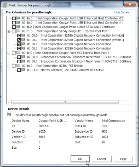
12. Select all the NICs corresponding to the Riverbed NIC from the list of available direct path devices.
The NICs are identified as Intel 82580 Gigabit Network Connections.
If a NIC is currently in use, vSphere displays a dialog box prompting you to confirm making this NIC a pass-through device. Click Yes to confirm the change.
Note: If you are configuring the 10-G fiber card, select the Broadcom Network Controller as a pass-through device. The Broadcom Controller may appear as Unknown Controller.
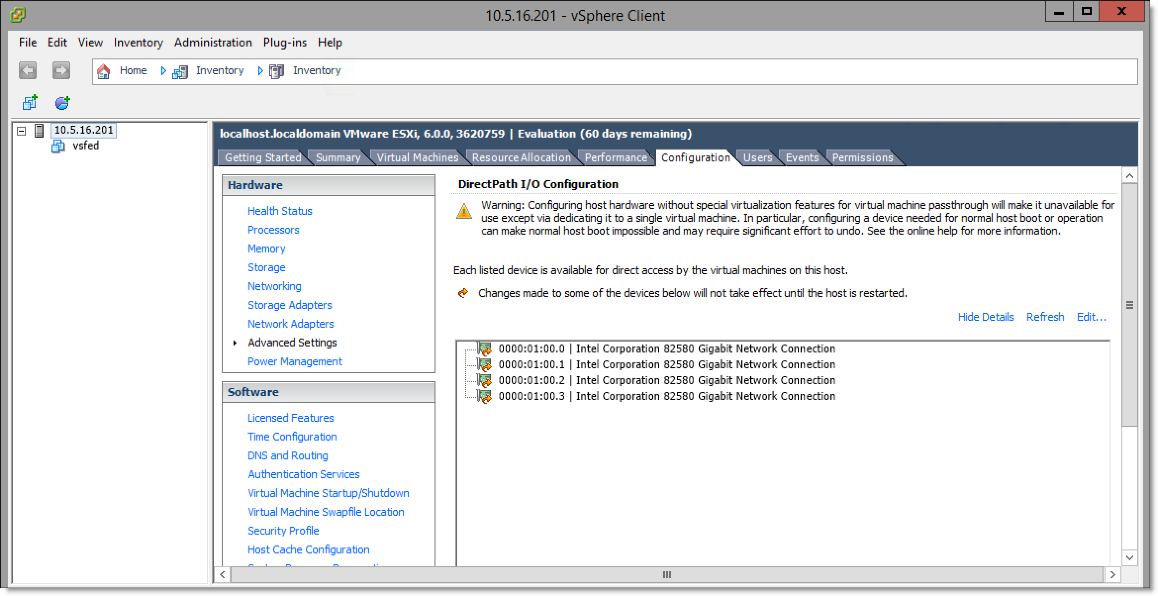
13. Click OK.
The NICs are displayed in the DirectPath I/O Configuration page as available for direct access by the virtual machines on the host.
Figure: DirectPath I/O Configuration page
14. Choose Inventory > Host: Reboot to reboot the host and apply the changes.
15. Ensure that the pass-through devices are appearing correctly. In the Inventory panel, select the host from the Configuration tab and select Advanced Settings.
Figure: DirectPath I/O Configuration - correctly configured devices
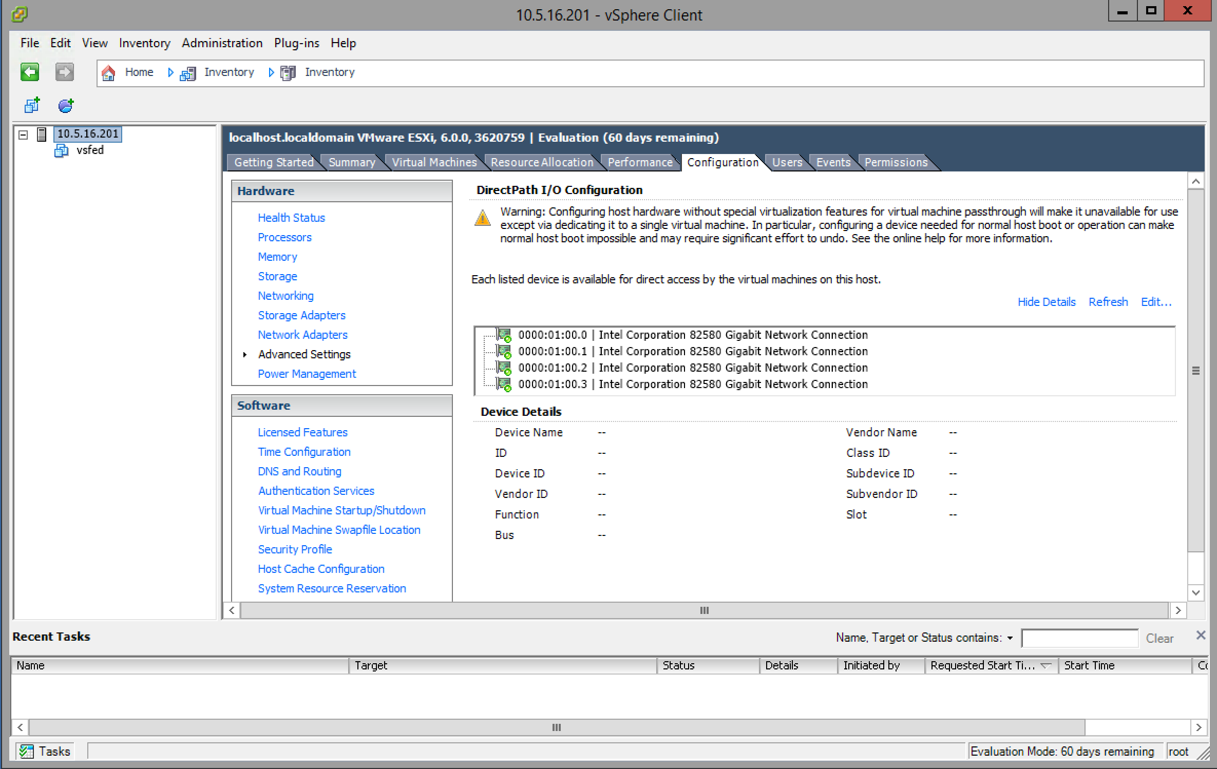
16. Ensure that the devices are correctly configured.
A green icon indicates that the device was correctly configured.
17. Log in to the vSFED VM.
The Configuration Jump Start wizard appears.
18. Enter no to these questions when prompted by the wizard.
Do you want to auto-configure using a SCC? no
Do you want to use the wizard for initial configuration? no
19. Enter the reset factory command to shut down the vSFED VM.
vsfed > enable
vsfed > configure terminal
vsfed (config) # reset factory
Resetting and halting the system... please wait.
20. Choose Inventory > Virtual Machine: Edit Settings.
The Virtual Machine Properties window appears.
21. Click Add... to display the Add Hardware wizard.
22. Select PCI Device from the Device Type list and click Next.
The Select PCI/PCIe Device page appears.
23. Select the first PCI device from the drop-down list and click Next.
After you have finished adding all bypass card NICs, they appear in the Hardware list of the Virtual Machine Properties window.
Figure: vSphere Virtual Machine Properties window - Riverbed bypass card mapped as PCI device
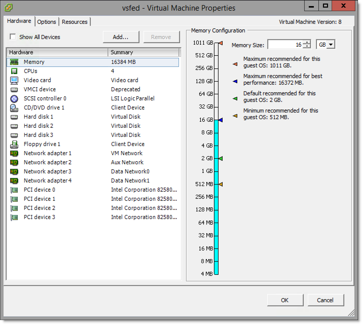
Note: If you are installing a 10-G fiber card, you also need to add the Broadcom Controller as a PCI device.
Mapping ESXi virtual switches to physical uplinks
You need to map the virtual switches to physical uplink ports. Before you start, make sure that you are familiar with the physical uplink ports. For example, which uplinks are wired, and for what purpose.
Note: It is not necessary to map all the virtual switches. For details, see the SteelFusion Design Guide.
To map ESXi virtual switches to physical uplinks
1. Select the host from the vSphere Inventory panel.
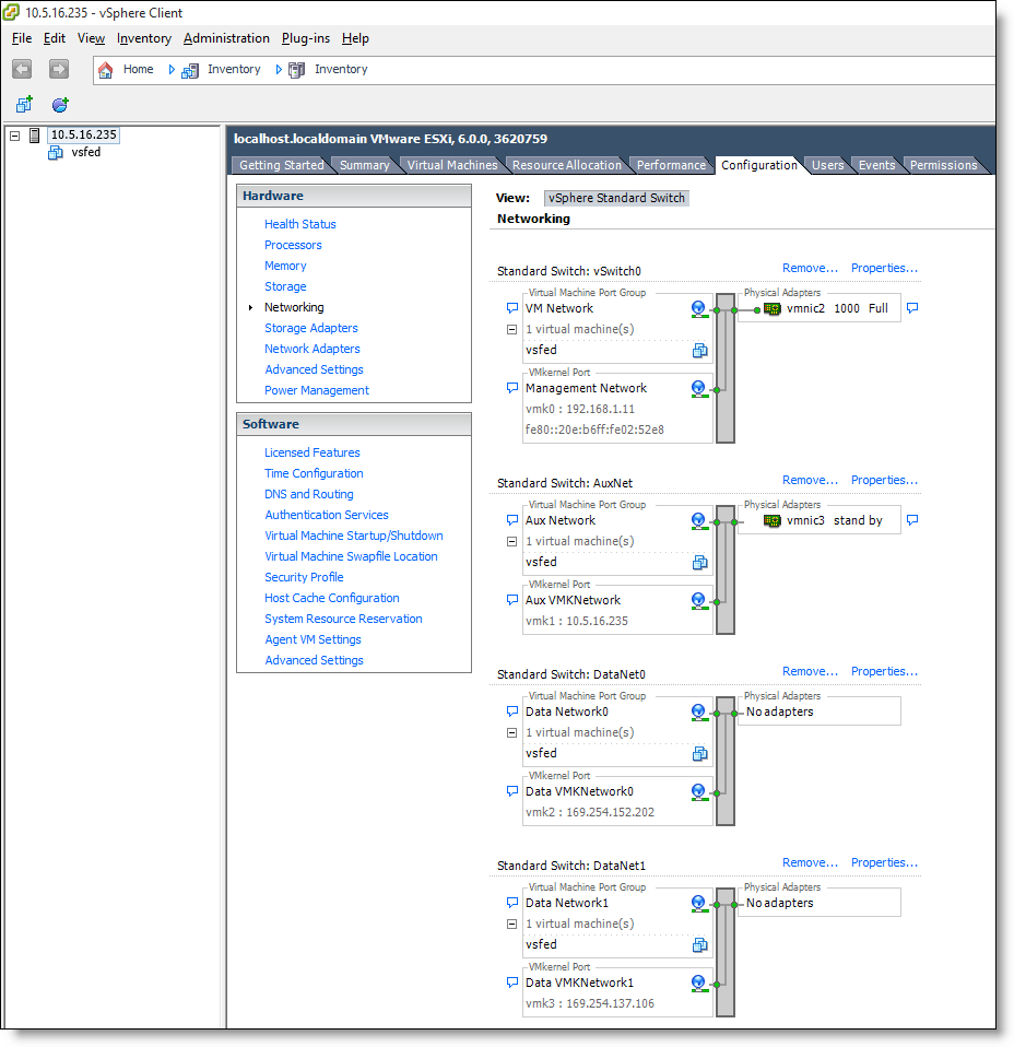
2. Select the Configuration tab, and then select Networking in the Hardware pane.
Figure: vSphere Networking tab - appliance without a bypass card
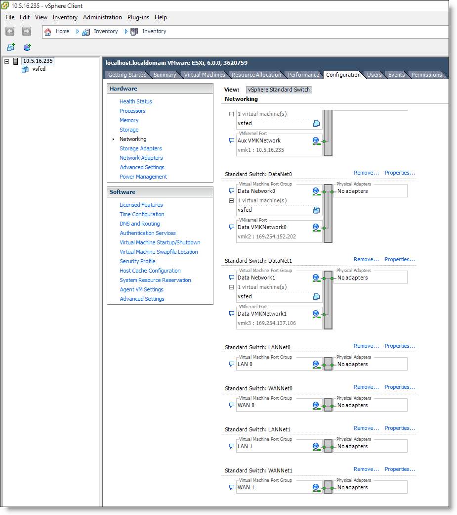
Figure: vSphere Networking tab - for appliances with a bypass card
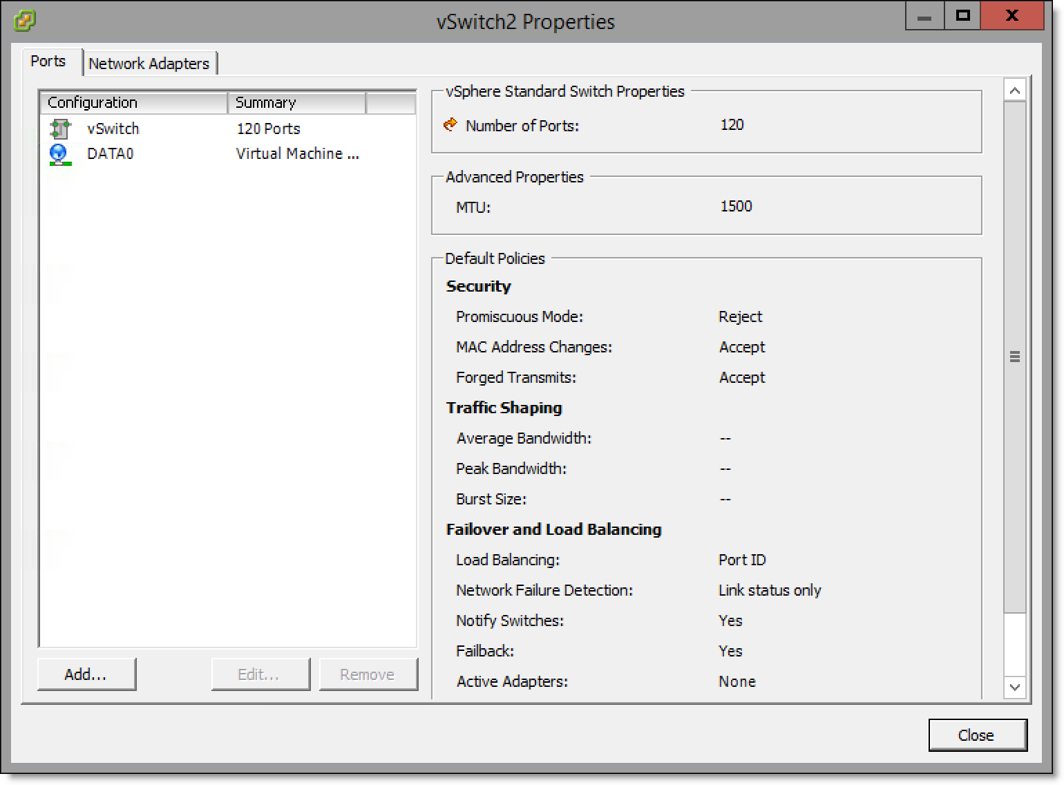
3. Select Properties for the vSwitch you would like to map. The vSwitch Properties window displays.
Figure: vSwitch Properties window - Ports tab
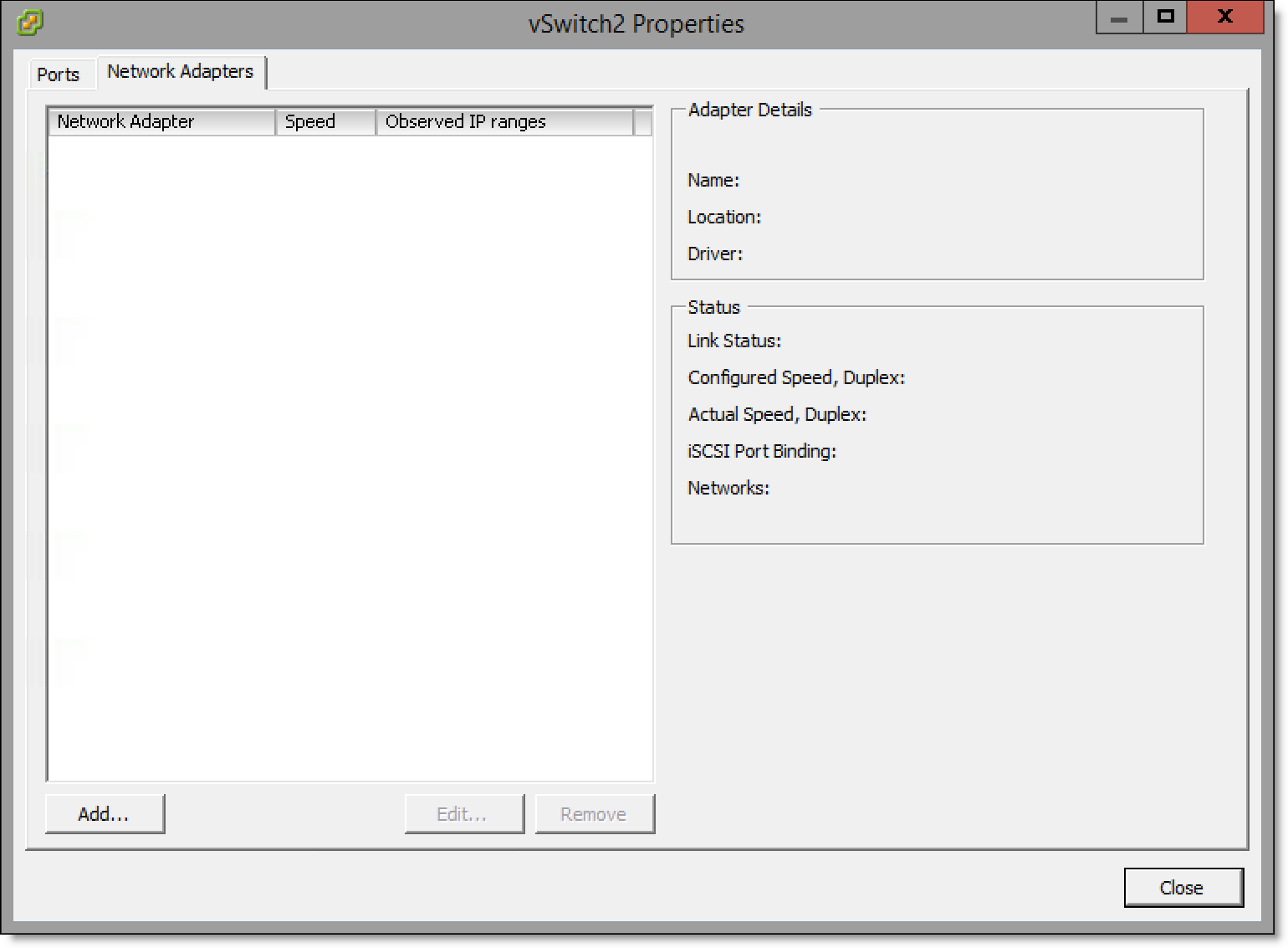
4. Select the Network Adaptors tab.
Figure: vSwitch Properties window - Network Adapters tab
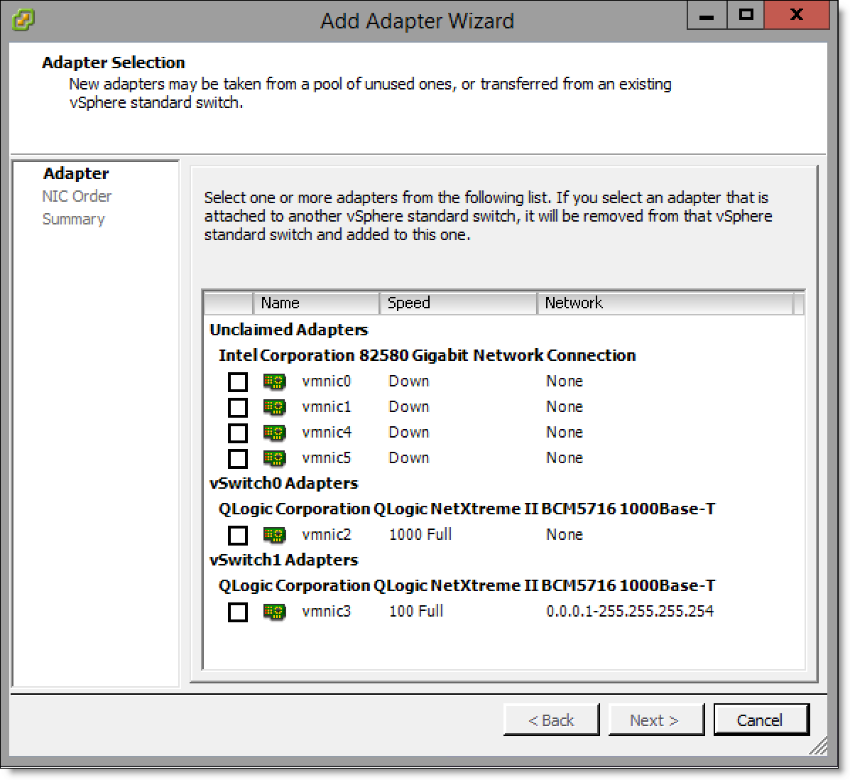
5. Click Add... to display the Add Adapter Wizard.
Figure: Add Adapter Wizard - Adapter Selection page
6. Select the check box of the adapter to use.
Figure: Add Adapter Wizard - selecting the adapter
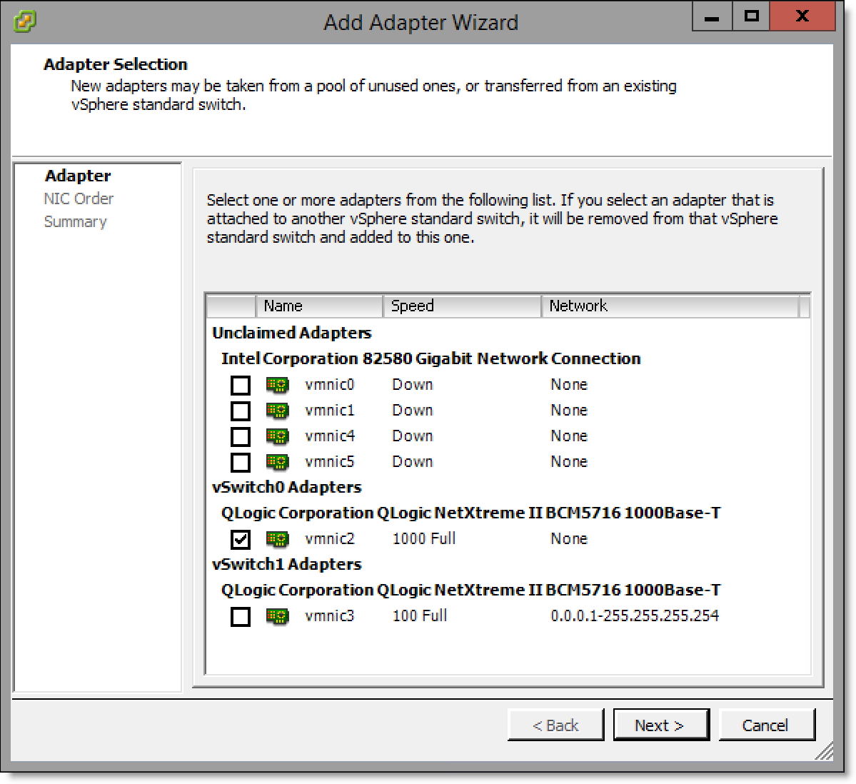
7. Click Next to display the Failover Order page.
Figure: Add Adapter Wizard - Failover Order page
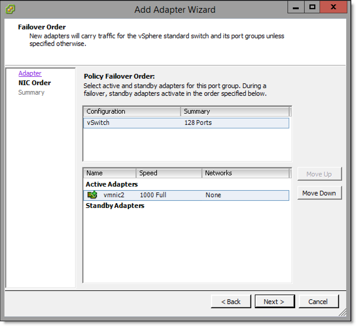
8. Click Next to display the Adapter Summary page.
Figure: Add Adapter Wizard - Adapter Summary page
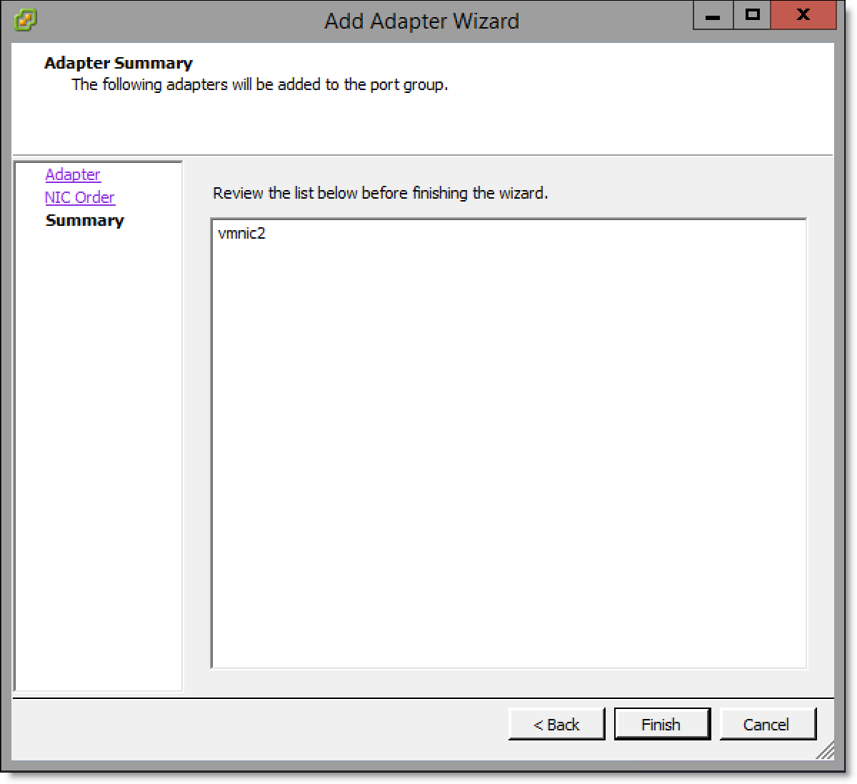
9. Click Finish.
10. Mark the uplink port on the appliance using a small label or similar method so the customer can clearly differentiate between each port.
11. Repeat
Step 3 through
Step 10 for all virtual switches to be mapped to a physical uplink.
Configuring Virtual Edge
After installation is complete, the system integrator will assist you in configuring the Virtual Edge appliance. For configuration details, see the “Configuring the Riverbed bypass card” and “Map ESXi virtual switches to physical uplinks” sections of the Virtual SteelFusion Edge System Integrator’s Guide.
Connecting Edge and Core
Once Virtual Edge installation and configuration are complete and the vSFED VM is powered on, contact Riverbed Support to guide you through the Edge replacement procedure in the SteelFusion Design Guide.
Troubleshooting
• ESXi installation appears to be successful but you are unable to boot into the installed ESXi - The installation may have occurred on a disk different from the boot disk of the appliance. In the BIOS boot menu, select the appropriate disk for booting and ensure that proper boot order is maintained.
• Installation does not process stating that corrupted RMA disk is attached - The USB device may have not been written to correctly, or it may have been ejected before all the data was written to it. Recreate and/or rewrite the image on the USB device and retry.
• Unable to install from the KVM console or the remote console of the server - RMA installation does not support KVM or remote console installations. The customer will need to physically attach the USB device to the appliance.