Interceptor Deployment Design
This chapter explains the basic design for physical in-path and virtual in-path Interceptor deployment. It includes the following sections:
Physical in-path Interceptor deployment
This section includes the following topics:
Overview of physical in-path Interceptor
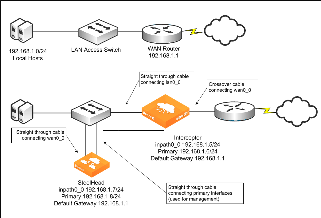
Figure: Interceptor deployment before and after shows a simple setup before and after a single Interceptor and SteelHead are deployed. The figure shows cabling for both the in-path interfaces and the primary (management) interfaces. No addressing changes are made on the hosts, switches, or routers. Only the cable configuration for the switch port that leads to the WAN is altered.
The SteelHead and Interceptors are allocated two IP addresses each:
• One is assigned to the primary interface and is used for administrative and reporting purposes.
• The other is assigned to the logical inpath0_0 interface and receives and transmits packets related to optimization.
Note: This chapter refers to the main interface on the Interceptor as inpath0_0. In certain circumstances (for example, fiber optic gigabit Ethernet), you can use a different interface (for example, inpath1_0).
Figure: Interceptor deployment before and after
This simple setup uses the following Interceptor features and configuration options (see the cross-references that follow for detailed information about each feature and configuration):
• You need only one Interceptor for redirection because only one Ethernet link carries traffic to or from the WAN.
• There is no optimization redundancy in case of an Interceptor failure because only one Interceptor is present.
• The Interceptor uses the default fail-to-wire mode, so that in the case of an Interceptor fault (including loss of power), traffic continues to pass to and from the WAN.
• Because only one SteelHead is present, there is no optimization redundancy in case of a SteelHead failure, nor can you configure traffic for optimization by multiple local SteelHeads.
• The SteelHead has one in-path cable connected to the switch. Unplugging the cable causes all optimization to cease.
• The SteelHead is connected to the LAN switch, not to the WAN router. This configuration typically minimizes the amount of traffic traversing the Interceptor.
For details on choosing between LAN-side and WAN-side SteelHead placement, see
Interceptor Clusters.
• The Interceptor and SteelHead in-path interfaces are in the same subnet. This setting isn’t required for Interceptor deployments.
• Because the in-path interface of the SteelHead in the cluster is on the same subnet as the Interceptor in-path interface, you only need to configure the WAN router as the default gateway on the Interceptors inpath0_0 interface.
• The Interceptor is deployed on a Layer-3 link.
• The site has no firewall or other network security device deployed.
1. Connect to the SteelHead and enter the following commands:
interface inpath0_0 ip address 192.168.1.7 /24
ip in-path-gateway inpath0_0 192.168.1.1
interface primary ip address 192.168.1.8 /24
ip default-gateway 192.168.1.1
in-path enable
in-path oop enable
steelhead communication enable
steelhead communication multi-interface enable
steelhead name interceptor main-ip 192.168.1.5
2. Connect to the Interceptor and enter the following commands:
in-path interface inpath0_0 enable
interface inpath0_0 ip address 192.168.1.5 /24
ip in-path-gateway inpath0_0 192.168.1.1
interface primary ip address 192.168.1.6 /24
ip default-gateway 192.168.1.1
steelhead communication multi-interface enable
steelhead name steelhead main-ip 192.168.1.7
The SteelHead is configured for virtual in-path mode and has the Interceptor in-path IP address configured as a connection-forwarding neighbor. The SteelHead in-path interface is assigned an IP address, as is the primary interface. In
Figure: Interceptor deployment before and after, both are in the same subnet, using the same next-hop gateway. Physically, the SteelHead wan0_0 and primary interface are cabled to the switch.
The Interceptor is cabled and addressed the same as a physically in-path deployed SteelHead. (Compare this configuration with the simple SteelHead physical in-path deployment in the SteelHead Deployment Guide.) The Interceptor has the SteelHead in-path IP address configured with the steelhead command. Both the SteelHead and Interceptor are configured as connection-forwarding neighbors. By default, they use TCP connections to their in-path IP addresses on port 7850 to communicate information regarding the connections that are redirected and the state of resource usage on the SteelHead.
When you use the multi-interface command, the Interceptor and SteelHead can communicate with a newer underlying version of the connection forwarding protocol. Although it isn’t strictly needed, we recommend that you enable multi-interface on both the SteelHead and the Interceptor in all new deployments, even if only a single in-path interface is in use.
Cabling and duplex
The same recommendations for cable selection and duplex configuration for in-path SteelHeads apply to the Interceptor. The IC9350 comes with a four-port 1-Gbps onboard card, similar to the 3U XX50 SteelHead. Most Interceptor deployments use 1 Gbps or higher speeds on their Ethernet bypass cards. For details, see the SteelHead Deployment Guide.
IP address and gateway selection
An IP address is required for each enabled Interceptor in-path interface.
In some environments, the link between the switch and the router might reside in a subnet that has no available IP address. You can meet the IP address requirement in several ways, including:
• expanding the subnet for the in-path interface.
• creating a secondary interface, with a new subnet and IP address on the router and switch, and pulling the Interceptor in-path interface IP address from the new subnet.
• creating a new 802.1Q VLAN interface and subnet on the router and switch link, and pulling the Interceptor in-path interface IP address from the new subnet. This configuration also requires entering the appropriate in-path VLAN tag on the Interceptor.
Default gateway and routing configuration
Each enabled in-path interface requires an IP address and, in almost every deployment, a default gateway. An Interceptor transmits packets whose destination addresses are to one of the following:
• A local SteelHead
• A local Interceptor
• A local server (only when the SteelHead rejects the incoming packet)
• A remote host (during the SteelHead autodiscovery process, or when it rejects the incoming packet)
If any of these devices are in different subnets than the in-path interface on the Interceptor, that in-path interface must have a route that specifies the next hop for those locations.
Because most Interceptor deployments have SteelHeads logically located on the LAN side, and because the number of subnets to reach remote hosts is expected to be far more than the number of subnets for local SteelHead and Interceptor in-path interfaces, the simplest and optimal configuration is that for each in-path interface to specify the WAN-side Layer-3 device as the default gateway. For each subnet containing local SteelHead or Interceptor in-path interfaces, configure a static route whose next hop is the LAN-side Layer‑3 device.
Figure: Quad Interceptor deployment with many subnets shows a sample Interceptor cluster in which nearly every in-path interface is in a different subnet.
Figure: Quad Interceptor deployment with many subnets
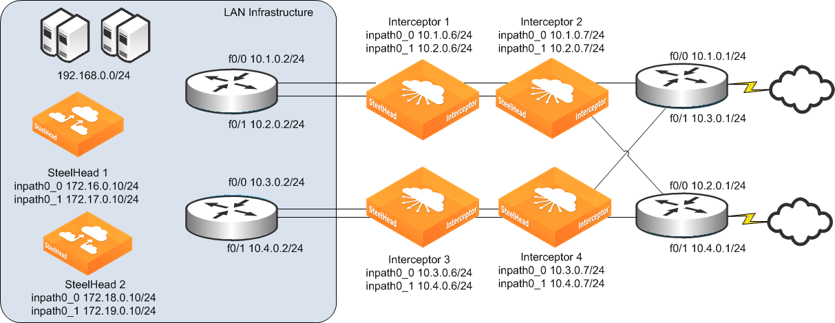
The following example shows the CLI configuration for the inpath0_0 interface of Interceptor 1 shown in
Figure: Quad Interceptor deployment with many subnets:
interface inpath0_0 ip address 10.1.0.6 /24
ip in-path-gateway inpath0_0 10.1.0.1
Interceptor
ip in-path route inpath0_0 10.2.0.0 255.255.255.0 10.1.0.2
ip in-path route inpath0_0 10.3.0.0 255.255.255.0 10.1.0.2
ip in-path route inpath0_0 10.4.0.0 255.255.255.0 10.1.0.2
ip in-path route inpath0_0 172.16.0.0 255.255.255.0 10.1.0.2
ip in-path route inpath0_0 172.17.0.0 255.255.255.0 10.1.0.2
ip in-path route inpath0_0 172.18.0.0 255.255.255.0 10.1.0.2
ip in-path route inpath0_0 172.19.0.0 255.255.255.0 10.1.0.2
Figure: Quad Interceptor deployment with many subnets shows that the Interceptor 1 inpath0_0 interface has a statically configured route to the 10.2.0.0/24 subnet, even though its inpath0_1 interface is located in the 10.2.0.0 subnet. You must use this configuration because Interceptor 1 might need to establish communication specifically from its inpath0_0 interface to Interceptor 2 inpath0_1 interface IP address.
If a firewall or other security device is used as a Layer-3 next hop for the Interceptor or SteelHead, the routing and default gateway configuration on the Interceptor and SteelHead is configured so that the firewall detects all or none of the packets associated with the autodiscovery process. For details, see
Figure: Firewall routing considerations.
Figure: Firewall routing considerations
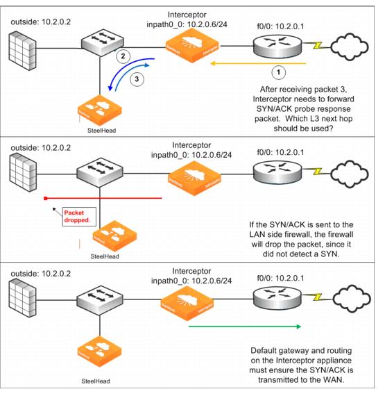
Figure: Firewall routing considerations shows a TCP SYN packet with a probe option received on the Interceptor WAN interface (1) as part of the autodiscovery process. The Interceptor forwards the packet to the SteelHead (2). The SteelHead creates a SYN/ACK probe response but doesn’t transmit it directly. As a part of the SteelHead-Interceptor redirection protocol, the SteelHead transmits this packet to the Interceptor (3), encapsulated in GRE. The Interceptor must unencapsulate and forward the packet, whose destination address is a remote host. It decides what the next hop for the packet is by using the in-path interface routing and default gateway configuration. If the routing configuration causes the SYN/ACK probe response packet to be sent to the LAN-side firewall, the firewall is likely to drop the packet because the firewall has not detected the initial SYN packet and therefore considers the SYN/ACK packet to be part of an unknown TCP flow. To ensure that autodiscovery works, the Interceptor must forward the packet to the WAN router. In the example shown in
Figure: Firewall routing considerations, this process is accomplished by making the WAN-side router the default gateway of the Interceptor in-path interface.
EtherChannel and LACP
You can deploy Interceptors across Ethernet links that are logically aggregated using EtherChannel or IEEE 802.3ad. These links use protocols such as Cisco Port Aggregation Protocol (PAgP) or the IEEE Link Aggregation Control Protocol (LACP) to negotiate how multiple physical links are bundled into a single logical link. The Interceptor passes through negotiation protocols without participating in them.
When deploying Interceptors on aggregated links, you must:
• configure each in-path interface to have a unique IP address.
• configure the no arp filter response command.
Note: The Interceptor must be physically in-path to use EtherChannel; you can’t use EtherChannel in a logical in-path configuration.
On EtherChannel or LACP aggregated links, a router or switch might transmit an ARP request for an in-path IP address on a link that traverses a different in-path interface on the Interceptor. To ensure that the Interceptor responds to ARP requests for in-path IP addresses regardless of which in-path interface receives the ARP request, use the no arp filter response command.
Figure: Two Interceptors in a serial deployment on a 2-port EtherChannel link shows two Interceptors with two links each deployed in series on a two-port EtherChannel. Each Interceptor in-path interface has its own unique IP address in the EtherChannel link's subnet. Router 1 and Router 2 each have a single IP address for the two physical links, but each Interceptor has two IP addresses, one for each in-path interface.
Figure: Two Interceptors in a serial deployment on a 2-port EtherChannel link
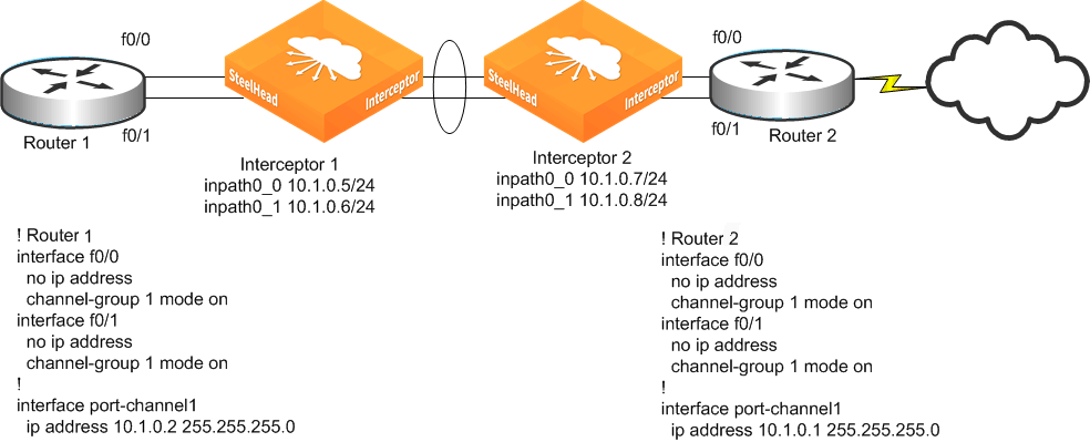
The following example shows the CLI configuration for the in-path and ARP filter configuration for Interceptor 1 as shown in
Figure: Two Interceptors in a serial deployment on a 2-port EtherChannel link:
in-path interface inpath0_0 enable
interface inpath0_0 ip address 10.1.0.5 /24
in-path interface inpath0_1 enable
interface inpath0_1 ip address 10.1.0.6 /24
no arp filter response
The Interceptor supports the port channel or channels through all of its available interfaces, including the four 10-Gbps in-path interfaces, or up to ten 1-Gbps interfaces. All links within the port channel must pass through the same Interceptor.
802.1Q VLAN trunks
You can deploy the Interceptor on 802.1Q trunk links and can use it to optimize connections whose packets pass through it with an 802.1Q header. The traffic redirection controls on the Interceptor, such as the in-path and load-balancing rules, can use the 802.1Q VLAN ID as a rule argument.
You can configure each Interceptor in-path interface with a VLAN ID. The Interceptor can optimize any traffic on the trunk and the native VLAN. When packets are sent from the in-path interface (for example, connection-forwarding traffic), the in-path VLAN tag is used. Configuration of the in-path interface VLAN ID is needed only if the in-path interface IP address belongs to a subnet whose traffic arrives on the LAN‑connected or WAN-connected equipment with a VLAN tag. For example, if the in-path IP is on the untagged native VLAN, then you don’t need the VLAN ID configuration.
Figure: WAN traffic through a single 802.1Q trunk line shows the
WAN access switch used to aggregate WAN traffic through a single 802.1Q trunk link. Because the WAN access switch doesn’t have Layer-3 addressing, the Interceptor must use Layer-3 Switch 1 as its default gateway. Layer-3 Switch 1 must have Layer-3 access to all remote sites that are optimized. The Interceptor can redirect traffic for optimization on all VLANs passing through the link, not just VLAN 10.
Figure: WAN traffic through a single 802.1Q trunk line
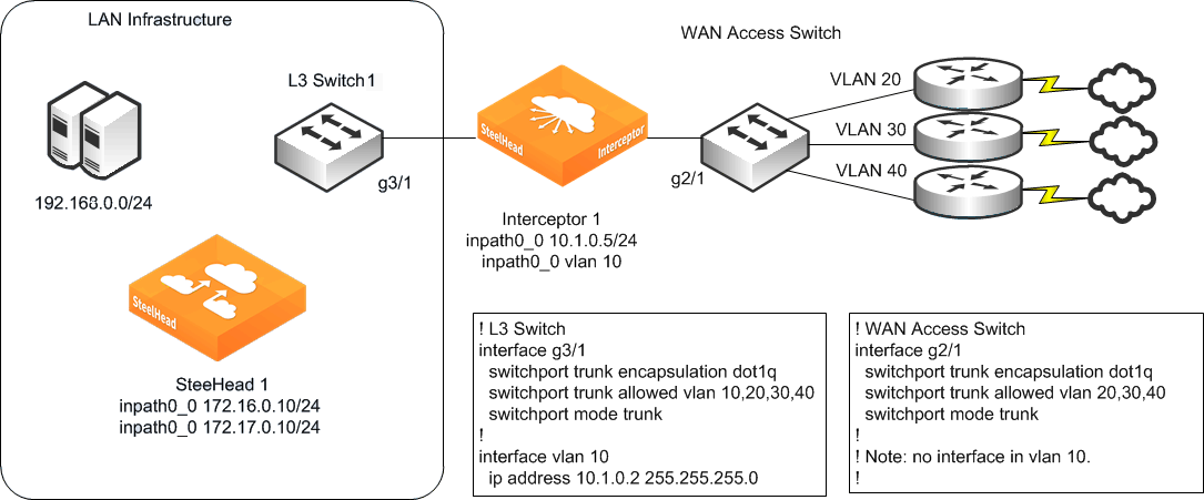
The following CLI configuration shows how the Interceptor in
Figure: WAN traffic through a single 802.1Q trunk line is configured to use VLAN 10:
in-path interface inpath0_0 ip address 10.1.0.5 /24
in-path interface inpath0_0 enable
in-path interface inpath0_0 vlan 10
ip in-path-gateway inpath0_0 10.1.0.2
You can deploy the Interceptor on links that are simultaneously 802.1Q trunks and part of a link aggregation bundle (for example, using Cisco EtherChannel).
Traffic redirected to the SteelHead replaces any VLAN tag information with the Interceptor in-path tag if you don’t enable VLAN segregation.
For more information about VLAN segregation, Interceptor appliance instances, VLAN transparency, and overlapping IP address support, see
VLAN Segregation.
When the Interceptor redirects 802.1Q encapsulated packets to a SteelHead, the 802.1Q header isn’t maintained on the packet. Thus any SteelHead in-path or peering rules that use the VLAN ID as a rule argument don’t work. Although the full address transparency WAN visibility mode is supported (including full address transparency with forward reset), the SteelHeads can’t maintain VLAN transparency for Interceptor redirected flows. Any traffic that isn’t redirected to the SteelHead maintains its 802.1Q header as it passes through the Interceptor.
Note: You can’t deploy an Interceptor on links for which the same IP address space might be used by different hosts, even if VLAN tags are used to differentiate between the overlapping IP addresses, unless you use VLAN segregation and the overlapping IP addresses are in different instances.
Trunk 802.1Q links are sometimes used to keep traffic with overlapping IP address spaces separate. For example, you can use an 802.1Q trunk to separate traffic from two organizations that use the same RFC 1918 private IP addresses to refer to different sets of resources. Deploying the Interceptor on these links isn’t supported because the Interceptor uses the actual IP addresses within the packets to track flows and can’t separate overlaps. If you use VLAN segregation, you can have overlapping IP addresses in different instances.
Physical in-path Interceptor failure modes
Failure results in the following behaviors:
• Interceptor failure - Nonoptimized traffic continues to flow through the Interceptor because the default mode for the network bypass cards is fail-to-wire (if you change to fail-to-block, traffic doesn’t flow). Because there is no other Interceptor to provide redundancy, existing connections either time out or reset because the packets for the optimized connection no longer are redirected to the SteelHead. The exact behavior depends on the applications and configuration of the remote SteelHead.
• SteelHead failure - If the SteelHead has a software fault, loses power, or becomes unresponsive, any connections optimized or in autodiscovery are reset or timed out. There is no impact to nonoptimized traffic flowing to the Interceptor. The Interceptor communicates with the SteelHeads using connection forwarding; as part of this protocol, the Interceptor exchanges heartbeat messages with the SteelHead. Interceptor 4.0 and later enables a Layer-7 heartbeat message by default. We recommend that you enable heartbeats on SteelHeads with RiOS 8.5 or later, using the steelhead communication heartbeat enable command.
The Interceptor continues to redirect packets (either for optimized connections or for connections that are just becoming established and are eligible for autodiscovery) to the SteelHead for 3 seconds.
Figure: Interceptor deployment before and after shows the default behavior with an Interceptor 2.0.3 or later.
For more information about how to design and configure Interceptor and SteelHead redundancy, see
Interceptor Clusters. The example shown in
Figure: Interceptor deployment before and after shows no redundancy.
Both the SteelHead and Interceptors and their network interface cards support fail-to-wire mode. In the case of software crashes, runaway software processes, or loss of power, the LAN and WAN for each individual in-path interface become internally connected as if they were the ends of a crossover cable. This configuration provides continued transmission of data over the WAN.
The exact configuration of the directly connected devices to the WAN and LAN ports have an impact on when traffic begins flowing through the in-path interface. Routing protocols, spanning tree settings, duplex negotiation, and other external factors can prevent traffic from flowing through an interface in fail-to-wire mode even when the actual network interface is ready to do so.
For details on external factors that can prevent traffic from flowing through an interface in fail-to-wire mode, see the SteelHead Deployment Guide.
All of the currently available network interface cards for the Interceptor also support a fail-to-block mode, in which, in the case of failures (as listed above), the LAN and WAN ports completely lose link status, blocking traffic along the path. Blocking network traffic triggers the routing and switching protocols of the network, forcing traffic along different paths to other Interceptors that can continue redirecting traffic.
The default mode for in-path interfaces is fail-to-wire. The following CLI output shows how you can view and control the current configuration:
interceptor (config) # interface inpath0_0 fail-to-bypass enable
interceptor (config) # show interfaces inpath0_0 configured
Interface inpath0_0 configuration
Enabled: yes
DHCP: no
IP address: 10.13.0.11
Netmask: 255.255.0.0
MTU: 1500
Failure mode: Bypass
interceptor (config) # no interface inpath0_0 fail-to-bypass enable
interceptor (config) # show interfaces inpath0_0 configured
Interface inpath0_0 configuration
Enabled: yes
DHCP: no
IP address: 10.13.0.11
Netmask: 255.255.0.0
MTU: 1500
Failure mode: Disconnect
interceptor (config) #
Interceptor link state propagation
The Interceptor supports the link state propagation (LSP) feature that also exists on the SteelHead. LSP helps communicate link status between the devices connected to the physical in-path Interceptor.
LSP monitors the link state of each Interceptor LAN and WAN pair. If either physical port loses link status, the link of the corresponding physical port is also disabled. LSP allows link failure to quickly propagate through the Interceptor, and it is useful in environments in which link status is used as a fast-fail trigger.
LSP is enabled by default. You can configure it with the in-path lsp enable command or from the Interceptor Management Console by choosing Networking: Networking > In-Path Interfaces and selecting Enable Link State Propagation.
For more information about LSP, see the SteelHead Deployment Guide.
Virtual in-path Interceptor deployment
This section includes the following topics:
Overview of virtual in-path Interceptor
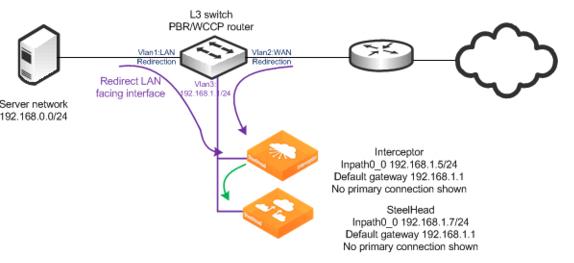
Figure: Virtual in-path Interceptor deployment shows an Interceptor virtual in-path deployment in which there is a single Interceptor and SteelHead. The router is performing PBR or WCCP redirection to send traffic to the Interceptor (shown in purple), and it redirects traffic to the SteelHead using the connection forwarding method. In this example, the SteelHead is configured in the same 192.168.1.0/24 network as the Interceptor. The SteelHead doesn’t need to reside in the same network as the Interceptor. You should not deploy the SteelHead where its traffic might hit one of the redirection interfaces of the router. For details, see
Unsupported virtual in-path Interceptor deployment.
Router configurations for redirecting traffic to an Interceptor through WCCP or PBR are identical to a virtual in-path SteelHead deployment. For more details, see the SteelHead Deployment Guide.
Figure: Virtual in-path Interceptor deployment
1. Connect to the SteelHead and enter the following commands:
interface inpath0_0 ip address 192.168.1.7 /24
ip in-path-gateway inpath0_0 192.168.1.1
in-path enable
in-path oop enable
steelhead communication enable
steelhead communication multi-interface enable
steelhead name interceptor main-ip 192.168.1.5
2. Connect to the Interceptor and enter the following commands (requires Interceptor 3.0 for virtual in‑path support):
in-path oop enable
in-path interface inpath0_0 enable
interface inpath0_0 ip address 192.168.1.5 /24
ip in-path-gateway inpath0_0 192.168.1.1
steelhead communication multi-interface enable
steelhead name steelhead main-ip 192.168.1.7
You can use WCCP for redirection to the Interceptor. Configure the Interceptor the same as a SteelHead. For details, see the SteelHead Deployment Guide.
The communication from the Interceptor to SteelHead uses connection forwarding over port 7850. The Interceptor applies the same load-balancing decisions to determine redirection to the SteelHeads (
Figure: Virtual in-path Interceptor deployment shows only one SteelHead). Use only WCCP, PBR, or Layer-4 redirection to forward traffic to the Interceptor.
Unsupported virtual in-path Interceptor deployment
Don’t deploy the local SteelHeads in situations in which traffic from them is unnecessarily redirected to the Interceptor by the router. You should deploy the SteelHeads on a separate router interface, rather than the redirecting LAN-facing or WAN-facing interfaces.
Figure: Unsupported virtual in-path Interceptor deployment
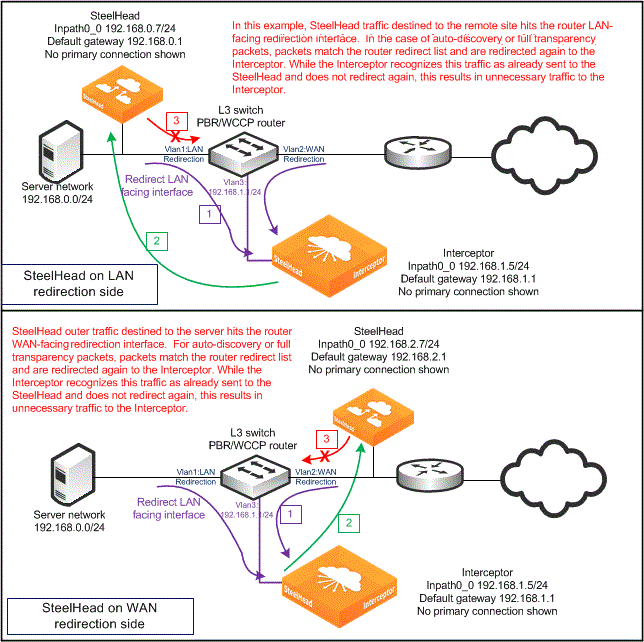
One typical scenario in a LAN-side deployment, is when a SYN packet from the server reaches the VLAN 1 switch interface and is redirected to the Interceptor. The Interceptor uses GRE to send the SYN packet to the SteelHead. The SteelHead attaches the autodiscovery probe and sends the SYN with TCP option toward the remote host. This SYN with TCP option reaches the switch VLAN 1 interface and is redirected unnecessarily to the Interceptor.
A similar scenario occurs with a WAN-side deployment, when a SYN packet from the WAN reaches VLAN 2 and is redirected to the Interceptor. The Interceptor uses GRE to send the SYN packet to the SteelHead, and it sends a SYN packet toward the local server. The SYN hits the VLAN 2 interface again and is redirected unnecessarily to the Interceptor.
Because the Interceptor detects that the traffic from the SteelHead doesn’t need to be redirected again, it causes unnecessary traffic on the network. These examples show the TCP handshake packets, but there are other and larger packets that can be also be needlessly redirected.
In-Path Interceptor failure modes
There is no redundancy used in the example shown in
Figure: Virtual in-path Interceptor deployment. Failure results in the following behaviors:
• SteelHead failure - If the SteelHead has a software fault, loses power, or becomes unresponsive, any connections optimized or in autodiscovery are reset or timed out. There is no impact to nonoptimized traffic flowing to the Interceptor. The Interceptor communicates with the SteelHead using connection forwarding; as part of this protocol, the Interceptor exchanges heartbeat messages with the SteelHead. The Interceptor continues to redirect packets (either for optimized connections, or for connections that are newly established and eligible for autodiscovery) to the SteelHead for 3 seconds. This process is the default behavior with an Interceptor 2.0.3 or later.
• Interceptor failure - PBR or WCCP both have mechanisms to stop forwarding traffic to a failed device. With WCCP, the router stops redirecting to a nonresponsive WCCP client device, and PBR is configured to use CDP or object tracking to determine if traffic should be sent to the Interceptor.
For details on PBR and WCCP, see the SteelHead Deployment Guide.
Figure: Virtual in-path Interceptor deployment shows that because there is no other Interceptor to provide redundancy, the existing connections either time out or reset because the packets for the optimized connection no longer are redirected to the SteelHead. New or pass-through connections aren’t redirected to the Interceptor.
Overview of redirection and optimization
The Interceptor redirects packets to a SteelHead so that it can be virtually located in the data transmission path of TCP connections. This process allows the SteelHead to perform autodiscovery and optimization of TCP connections to remote SteelHeads. The Interceptor must redirect the host-to-WAN traffic for optimized connections, and if an optimized connection uses the full address transparency WAN visibility mode, the Interceptor must also redirect the incoming transparent traffic from remote SteelHeads. Traffic for nonoptimized connections is bridged between the LAN and WAN interface pairs of the Interceptor; it isn’t redirected to a SteelHead.
For details on WAN visibility modes, see the SteelHead Deployment Guide.
Redirection is primarily controlled by the Interceptor load-balancing rules. They can control what traffic should be redirected for optimization and to which SteelHead or group of SteelHeads.
The Interceptor has other control rules that can affect what traffic should be optimized, including in-path rules. These rules are similar to the SteelHead in-path rules. The Interceptor doesn’t have a control mechanism that corresponds directly to the SteelHead peering rules. The Interceptor load-balancing rules can achieve the same effect as both the SteelHead in-path and peering rules.
As shown in
Figure: Interceptor deployment before and after, neither the SteelHead nor the Interceptor has any manually configured in-path rules or load-balancing rules. The default redirection configuration for the Interceptor matches a default autodiscovery configuration for the SteelHead. The Interceptor, by default:
• redirects TCP SYN packets arriving on its LAN interface to the SteelHead for all traffic except secure, interactive, or Riverbed internal protocols.
• redirects any arriving SYN packets that have embedded autodiscovery TCP options in them.
• redirects traffic from the local host to the remote host if the traffic is for an optimized connection.
• doesn’t redirect traffic that has been redirected by another Interceptor in a cluster to a local SteelHead because the Interceptor changes the TCP/IP destination fields and no longer matches the TCP/IP destination fields for an optimized connection.
• doesn’t redirect traffic from the remote host to the local host, including traffic from a SteelHead located on the WAN side of an Interceptor. An exception to this rule is if a full transparency TCP option is present. The full transparency TCP option indicates the packet is sent from a remote SteelHead to a local SteelHead. The full transparency TCP option includes information indicating the destination SteelHead. The Interceptor checks if the destination SteelHead is part of the local cluster before redirection.
Note: SteelHeads in a connection-forwarding cluster, including Interceptor, ensure that MAPI and FTP (which use multiple TCP connections for a session) are optimized by the same SteelHead. This redirection action happens before in-path rules are applied because the redirecting device (SteelHead or Interceptor) redirects to the SteelHead for that SteelHead to take action.
The Interceptor redirects packets by using two methods:
• GRE encapsulation during autodiscovery
• TCP/IP destination field changes during data transmission
A network sniffer on the Interceptor LAN port detects TCP SYN and SYN/ACK packets transferred between the SteelHead and Interceptor with GRE encapsulation. The SteelHead can add TCP autodiscovery options, or take action due to TCP autodiscovery options embedded by remote SteelHeads. For optimized connections, a network sniffer detects traffic from hosts to the WAN arriving at the Interceptor WAN port. The traffic is then transmitted from the LAN port with its destination IP address changed to a local SteelHead in-path IP address and a dynamically determined TCP port.
Figure: General flow for traffic redirection shows general packet redirection. The management interface connections aren’t used for redirection and aren’t shown.
Figure: General flow for traffic redirection
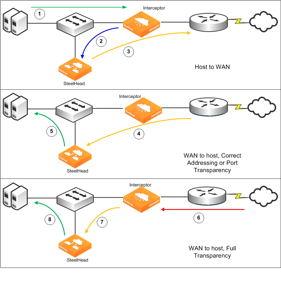
Host-to-WAN traffic (1) reaches the Interceptor on its way to the WAN. The Interceptor receives the traffic, and then it transmits the packets to the SteelHead from the same LAN interface on which it arrived (2). When the SteelHead cluster needs to transmit packets to a remote SteelHead, it sends the packets from its WAN interface (3) and passes the traffic through the Interceptor.
The WAN-to-host traffic behavior depends on the WAN visibility mode used for the optimized connection. For correct addressing or port transparency, optimized traffic from the remote SteelHead passes through the Interceptor (4) and is received directly by the SteelHead—the destination of the traffic. When the SteelHead transmits the native form of the traffic (5), it doesn’t need to traverse the Interceptor because it is destined directly for the host. The source information for this traffic is that of the remote host. When full-transparency optimized traffic arrives from a remote SteelHead (6), the Interceptor recognizes the traffic because of the embedded full transparency option in the packet's TCP option list. It swaps the IP address and TCP port information between the option packet and the actual TCP/IP packet headers and then transmits the packet to the SteelHead (7). As in the nonfull-transparency case, the SteelHead transmits the native data to the host (8)and doesn’t pass through the Interceptor.
For more information about traffic redirection, see
Traffic Redirection.
Deployment verification
You can control the installation of the Interceptor and SteelHead so that you can power on and install both in the network but don’t redirect or optimize traffic. This control enables you to verify the configuration before the system attempts optimization.
After you verify configuration, we recommend that you identify a small subset of traffic (as little as a single or a few hosts) and select only the traffic for the subset for redirection by the Interceptor. We also recommend that you verify traffic to all remote sites, whether they have SteelHeads or not. After this verification, you can configure traffic for all remaining hosts for redirection and optimization.
Using the example network shown in
Figure: Interceptor deployment before and after, the minimum amount of verification you need to ensure that the SteelHead and Interceptor in-path IP addresses can ping each other, the local WAN router, and a remote SteelHead. Use the
debug validate deployment command to verify that both the SteelHead and Interceptor have the correct connection-forwarding configuration.
For details on deploying an Interceptor in a network, see
Installation and verification best practices.
GRE, MPLS, and VRF
The Interceptor redirects only TCP/IP Ethernet packets or 802.1Q tagged TCP/IP packets with a single 802.1Q header.
Other forms of encapsulation or packet labeling—including GRE, QinQ, or MPLS—pass through the Interceptor and can’t be redirected to a SteelHead. The Interceptor doesn’t support 802.1Q links separating overlapping IP address spaces, such as those associated with VRF instances, unless you use VLAN segregation.
For more information about VLAN segregation, see
VLAN Segregation.
The phrase passing through GRE refers to GRE-tunneled traffic not destined for the Interceptor. WCCP can use GRE for redirecting traffic between a WCCP router and virtual in-path deployed Interceptor.
QoS in an Interceptor deployment
We recommend that you use QoS marking with a virtual in-path Interceptor deployment. You can take advantage of the deep packet inspection capabilities in the SteelHead to classify and mark traffic according to a much larger set of rules. QoS marking enables other network devices (such as routers) to act on DSCP marking to place traffic in a more appropriate class and thereby enforce QoS.
If you use QoS enforcement on SteelHeads deployed in an optimization cluster with an Interceptor, be aware of the following limitations:
• There is no coordination of QoS enforcement between SteelHeads in a cluster.
• The Interceptor doesn’t distribute traffic equally to the SteelHead in the cluster, so you might not be able to determine the WAN QoS enforcement rate on a SteelHead in the cluster.
• The SteelHeads don’t see the pass-through traffic unless path selection is enabled.
If you deploy the Interceptor virtually in-path, the SteelHeads might not detect all traffic traversing the WAN link. Pass-through traffic isn’t accounted for unless you enable path selection on the Interceptor, either as general pass-through traffic or hardware‑assisted pass-through traffic. Any given SteelHead in the cluster doesn’t detect all of the traffic.
For all of the SteelHeads to detect all of the traffic, you must coordinate between SteelHeads or distribution between SteelHeads. In an optimization cluster with Interceptor appliances or between SteelHeads, QoS enforcement isn’t coordinated. Some challenges include distributing traffic among SteelHeads and configuring QoS enforcement on a percentage of the overall WAN rate: for example, if you add or remove a SteelHead from the cluster.
IPv6 support for traffic optimization
Interceptor 6.0 supports redirection of IPv6 traffic for optimization. Interceptor 6.5 introduced single‑stack support where only IPv6 addresses are used for optimization. This section describes how a cluster of Interceptors and SteelHeads can perform optimization for IPv6 traffic.
Note: The examples in this section are for dual-stack deployments where IPv4 and IPv6 addresses are used simultaneously.
Addressing on the Interceptor is performed the way it is on the SteelHead. The Interceptor supports a single, system-generated link-local address and a user-assigned IPv6 address for each interface (primary, auxiliary, and in-path). The system automatically assigns the link-local address as the network identifier using FE80 in the first 64 bits and a modified EUI-64 identifier for the host bits, following the RFC 4291 standard. The link-local address can’t be changed. It is used as part of IPv6 neighbor discovery, which is analogous to the address resolution protocol for IPv4.
An administrator must manually configure the user-assigned IPv6 address; the address can’t be derived from a stateless, automatic configuration or from the dynamic host communication protocol for IPv6.
The IPv6 gateway is also user-assigned, and you can link it to the local address of the router or the address on the same subnet as the manually assigned address. RiOS doesn’t support receiving router advertisements as a way of discovering the IPv6 gateway. Configure the link-local address for a virtual router when you use a first-hop redundancy protocol: for example, HSRPv6.
When you configure SteelHead and Interceptor appliances, remember that the Interceptor cluster with SteelHead appliances relies on connection forwarding, which can use IPv4 addresses. In Interceptor 6.5, the addresses used can be changed for single-stack IPv6 deployment. When the connection is established and optimized, traffic is redirected through network address translation (NAT) and is destined for the SteelHead in-path interface IPv6 address. You can optimize TCP-over-IPv4 and TCP-over-IPv6 traffic concurrently; however, for IPv6 traffic to be optimized between the SteelHead appliances using TCP over IPv6, the SteelHead appliance should use RiOS 9.5 or later.
By default, both IPv4 and IPv6 traffic is redirected, even if no rules are configured. You can change the configuration from the default value all (all IPv4) to all-ip (all IPv4 traffic and all IPv6 traffic) using the in-path rule table for the source (src) and destination (dest) fields.
You can also configure new in-path rules and new load-balancing rules with these options for supporting IPv4 and IPv6 traffic:
• All IP (for both IPv4 and IPv6 traffic)
• All IPv4 (for all IPv4 traffic)
• All IPv6 (for all IPv6 traffic)
• IPv4 (for one or more specific IPv4 addresses)
• IPv6 (for one or more specific IPv6 addresses)
Note: Starting in RiOS 9.5, the SteelHead can also use IPv6 over the WAN for optimized connections. RiOS 9.6 or later is required for single-stack IPv6 deployments; otherwise, IPv4 is used for connection forwarding.
These features are compatible with IPv6:
• Xbridge
• Connection tracing
• In-path rules
• Fair-peering (versions 1 and 2)
Important: Single-stack IPv6 deployments aren’t compatible with virtual in-path Interceptors or path selection on Interceptors.
Figure: TCP-over-IPv6 traffic deployment shows a sample deployment for TCP-over-IPv6 traffic.
Figure: TCP-over-IPv6 traffic deployment
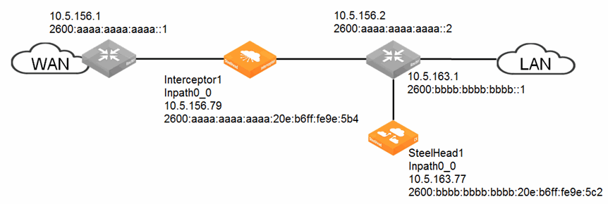
To configure TCP-over-IPv6 traffic as shown in Figure: TCP-over-IPv6 traffic deployment 1. Connect to the Interceptor appliance and enter these commands:
interface inpath0_0 ip address 10.5.156.79 /24
ip in-path-gateway inpath0_0 10.5.156.1
ip in-path route inpath0_0 10.5.163.0 255.255.255.0 10.5.156.2
in-path interface inpath0_0 enable
interface inpath0_0 ipv6 address 2600:aaaa:aaaa:aaaa:20e:b6ff:fe9e:5b4 64
ipv6 in-path-gateway inpath0_0 2600:aaaa:aaaa:aaaa::1
ipv6 in-path route inpath0_0 2600:bbbb:bbbb:bbbb::/64 2600:aaaa:aaaa:aaaa::2
steelhead name steelhead1 main-ip 10.5.163.77
2. Connect to the SteelHead appliance and enter these commands:
interface inpath0_0 ip address 10.5.163.77 /24
ip in-path-gateway inpath0_0 10.5.163.1
interface inpath0_0 ipv6 address 2600:bbbb:bbbb:bbbb:20e:b6ff:fe9e:5c2 64
ipv6 in-path-gateway inpath0_0 2600:bbbb:bbbb:bbbb::1
in-path simplified routing "none"
steelhead communication enable
in-path oop enable
in-path peering-ipv6 enable
steelhead communication multi-interface enable
steelhead name interceptor1 main-ip 10.5.156.79
Important points about IPv6 single-stack deployments
• In a single-stack IPv6 deployment, the connection forwarding commands—steelhead name <name> main-ip <address> and steelhead interceptor name <name> main-ip <address>—use IPv6 addresses.
Before you configure the or SteelHead Interceptor for an IPv6 single-stack deployment, make sure the list of connection forwarding neighbors doesn’t contain any configured IPv4 neighbors.
• The and SteelHead Interceptor must be set up to allow connection forwarding in IPv6 mode. To allow connection forwarding in IPv6 mode, use these commands on the SteelHead Interceptor:
• steelhead communication mode-ipv6
• steelhead interceptor communication mode-ipv6
• The load-balancing rules in a single-stack IPv6 environment use the main IPv6 address of the .
For more information about commands, see the Riverbed Command-Line Interface Reference Manual.