Managing Hybrid Network Services
This chapter describes how to manage hybrid network services, such as path selection, secure transport, QoS, and applications. This chapter includes these sections:
Managing path selection
You configure path selection in the Path Selection page. This section includes these topics:
With RiOS 9.0 and SCC 9.0 or later, existing path selection rules aren’t migrated to SteelHeads. You must create new path selection rules in the SCC 9.0 or later. These new path selection rules apply only to RiOS 9.0 and later. Legacy path selection rules apply only to SteelHeads running RiOS earlier than 9.0.
Path selection ensures that the right traffic travels to the right path by choosing a predefined WAN gateway for traffic flows in real-time, based on availability. In path selection, you define a path, called an uplink, by specifying a WAN egress point and providing a direction for the egressing packets to take. This granular path manipulation enables you to better use and more accurately control traffic flow across multiple WAN circuits.
Enabling Internet paths makes efficient use of existing resources by taking advantage of both private and public links. Path selection provides the right performance levels for your applications and saves on bandwidth costs by optimizing the use of available bandwidth.
Path Selection probing must be able to distinguish between true path availability versus false positives or inaccurate assumptions of service availability. For detailed information about path selection probing best practices, see
“Hybrid network path selection probing techniques” on page 59.Using the SCC, you can define application policies based on business requirements, enabling you to easily leverage and control hybrid networks for accelerated application delivery. Application policies enable you to configure and reuse a single path selection or QoS rule for multiple applications. Using an application policy in path selection or QoS rules reduces the number rules significantly. The SCC manages hundreds of applications, including policy configuration, reporting, and troubleshooting.
To simplify SCC configuration, you define application policies based on application groups using the widget in the Path Selection page. For details, see
“Managing path selection” on page 329. After you define the application policy, you use it to configure path selection rules. An application group is a logical grouping of similar applications matched by the type of network traffic. A separate application group allows for the configuration of multiple path selection rules, using the same application without having to repeat the application definition for each rule. For each application, you also specify uplinks to monitor path availability; you configure the latency of the path (timeout) and the loss observed (threshold).
If the SCC and SteelHeads are both running 9.2 and later, for the initial configuration the SCC pushes the entire configuration. For SteelHeads and an SCC running 9.2 or later, any changes made after the initial push, the SCC pushes only the modified settings to ensure improved response times and throughput performance. If the SCC and SteelHeads are both running 9.0 and 9.1, when you push configuration changes, whether the initial push or after, the SCC deletes the entire configuration and replaces it with the new configuration settings, which can slow response times and performance.
You can’t migrate your previously defined path selection rules to SCC 9.0 or later.
For detailed information about path selection common use cases and how to configure them, see the SteelHead Deployment Guide and the SteelHead User Guide for SteelHead CX.\
Configuring application groups using the path selection wizard
SCC includes a wizard that enables you to define path selection rules for application groups. The wizard describes each application group, some sample applications in that group, and provides a recommendations for uplink preferences. Using the wizard you create path selection rules and create the uplink preference order for each application group.
The application group determines the global performance for an application, including latency priority. Application groups provide a powerful way to group traffic profiles and to specify policies based on the profile.
When you prioritize the application group, you select the uplink type for uplinks and the default action for each: for example, Relay and Drop.
To configure application groups and path selection rules
2. Choose Manage > Services: Path Selection to display the Path Selection page.
3. Under Getting Started with Path Selection, click Begin Setup to display the getting started widget.
Path selection widget
4. Complete the configuration as described in this table.
Control | Description |
Application Group | Select an application group from the drop-down list (highest priority to lowest): •Business Bulk - Captures business-level file transfer applications and protocols, such as CIFS, SCCM, anti-virus updates, and over-the-network backup protocols. •Business Critical - Captures business-level, low-latency transactional applications and protocols, such as SQL, SAP, Oracle and other database protocols, DHCP, LDAP, RADIUS, and routing and other network communication protocols. •Business Productivity - Captures general business-level productivity applications and protocols, such as email, messaging, streaming and broadcast audio/video, collaboration, Intranet HTTP traffic, and business cloud services O365, Google applications, SFDC, and others through a whitelist. •Business Standard - Captures all intra-network traffic going within local subnets as defined by the uplinks on the SteelHead. Use this class to define the default path for traffic not classified by other application groups. •Business VDI - Captures real-time interactive business-level virtual desktop interface (VDI) protocols, such as Citrix CGP/ICA, Remote Desktop Protocol (RDP), and Virtual Network Computing (VNC). •Business Video - Captures business-level video conferencing applications and protocols, such as Microsoft Lync and RTP video. •Business Voice - Captures business-level Voice over IP (VoIP) applications and protocols (signaling and bearer), such as Microsoft Lync, RTP, H.323 and SIP. •Recreational - Captures all Internet-bound traffic that hasn’t already been classified and processed by other application groups. •Standard Bulk - Captures general file transfer protocols, such as FTP, torrents, NNTP/usenet, NFS, and online file hosting services Dropbox, Box.net, iCloud, MegaUpload, Rapidshare, and others. •Custom Applications - Captures user-defined applications that haven’t been classified into another application group. |
5. Click Configure to expand the page.
Configuring path selection rules for application groups
6. Complete the configuration as described in this table.
Control | Description |
Uplink Type | Select and reorder the uplinks. •To confirm that you have chosen the correct application group for your path selection rule, read the uplink recommendations for the application group on the right side of the pane. These recommendations change based on the application group you have selected. •To move the uplink type up or down in the priority list, mouse over the uplink type you want to move, click and hold the cursor over the three bars on the right and move the link up or down the priority list. An uplink type is a label that describes the type of traffic for the uplink. For details about creating uplinks and defining the uplink type, see “Defining uplink types” on page 210. |
If all checked uplinks are down | Select what happens if all the uplinks specified in the rule are down. These settings are available even when no uplinks are selected. •Relay - Sends the traffic unmodified out of the WAN side on whichever in-path it came in on. This is the default setting. •Drop - Drops the packets in case of failure of all three (primary, secondary, tertiary) paths. Select this option when you don’t want the traffic to pass on any of the uplinks specified in the rule, not just the primary. Dropping traffic is useful if you prefer not to use bandwidth on the secondary (or tertiary) uplinks in case of failure on the primary path. |
Save Rule | Saves your path selection rule. |
Back | Returns to the previous screen. |
Configuring path selection rules
To configure path selection, you define path selection rules to direct traffic to any site.
Path Selection rules direct matching traffic onto specific uplinks. Traffic is matched by a combination of application and destination site.
You can create multiple rules for a site. When multiple rules are created for a site, the rules are followed in the order in which they’re shown in the Path Selection page and only the first matching rule is applied to the site.
The network topology definition includes direct uplinks on a SteelHead. A SteelHead uses a direct uplink to steer packets to a specific gateway. The SteelHead can reach the gateway over Layer 2, so it can send packets directly to that gateway.
You configure a direct uplink using a network and gateway IP address. For details, see
“Defining sites” on page 186. When you define path selection rules, you specify the uplink preferences for certain traffic.
Path selection uses only local uplinks. You can create site connectivity templates with one or more uplinks for use with multiple sites that share the same uplink structure, such as dual uplink sites or branch sites. When the site connectivity template is applied to a site, the uplinks defined in the template uplinks are cloned. For details about creating site templates, see
“Defining site connectivity templates” on page 191.The default path selection rule is Any, that is, any application or application group. The Any rule combines identifications of all known configured sites, including the Default-Site. Rather than configuring a separate identical path selection rule for every known site, select the Any rule to match the destination address of every configured site. The Any default rule steers the configured application and any matching configured site, or the default-site, onto the selected uplink. Using the Any default rule reduces the configuration steps required, yet provides a common application steering design.
To configure path selection
2. Choose Manage > Services: Path Selection to display the Path Selection page.
Enabling path selection
3. Select the check box. Path Selection is disabled by default. After you enable path selection, it processes new flows; it doesn’t process preexisting flows.
4. Click Save to save your settings; click Revert to disable path selection.
5. Under Path Selection Rules, click + Add a Rule to display the pop-up window.
Adding a rule
6. Complete the configuration as described in this table.
Control | Description |
Application/Application Group | Identify the traffic flow by selecting an application or application group for the Riverbed Application Flow Engine (AFE). Type the first few letters of the application in the Application/Application Group field. As you type the name of an application, a menu appears and lists available applications and groups that match your typing. Select an application from the list. The default setting is any application or application group. The Any setting combines identifications of all known configured sites, including the Default-Site. Rather than configuring a separate identical path selection rule for every known site, select the Any setting to match the destination address of every configured site. When you select Any, path selection steers the configured application and any matching configured site, or the default-site, onto the selected uplink. Using the Any setting reduces the configuration steps required, yet provides a common application steering design. |
Uplinks | Specify the uplink and DSCP. The uplinks you select cascade from one to the next, based on availability. •Uplink Type - Define the type of traffic flow in order of priority and whether the network is secured: –primary –primary (secured) –secondary –secondary (secured) –tertiary –tertiary (secured) If the primary uplink assigned to a connection becomes unavailable, the SCC directs traffic through another available uplink and triggers an alarm. When the original uplink comes back up, the SCC redirects the traffic back to it. •DSCP - Select Preserve or the DSCP level from the drop-down list. DSCP marks the uplink for a given flow to allow an upstream router to steer packets based on the observed marking. The default marking is Preserve. Preserve specifies that the DSCP level or IP ToS value found on pass-through and optimized traffic is unchanged when it passes through the appliances. |
Add Uplink | Adds your uplink settings. |
If all the above uplinks are down: | Select how the system handles packets if the default uplinks go down from the drop-down list: •Relay - Sends the traffic unmodified out of the WAN side on whichever in-path it came in on. This is the default setting. •Drop - Drops the packets in case of failure of all three (primary, secondary, tertiary) paths. Select this option when you don’t want the traffic to pass on any of the uplinks specified in the rule, not just the primary. Dropping traffic is useful if you prefer not to use bandwidth on the secondary (or tertiary) uplinks in case of failure on the primary path. |
Save | Saves your settings. |
Pushing your settings and viewing push status
You can push your path selection settings from the Policy Push Control on the right side of the page. You can also view push status from the Push Status panel on the right side of the page.
If the SCC and SteelHeads are both running 9.2 and later, for the initial configuration the SCC pushes the entire configuration. For SteelHeads and an SCC running 9.2 and later, any changes made after the initial push, the SCC pushes only the modified settings to ensure improved response times and throughput performance. If the SCC and SteelHeads are both running 9.0 and 9.1, when you push configuration changes, whether the initial push or after, the SCC deletes the entire configuration and replaces it with the new configuration settings, which can slow response times and performance.
When you perform a policy push, the SCC is the master configuration; any local changes made on SteelHeads are overwritten.
To push settings
1. Under Policy Push Control on the right side of the page, click Include in Push to expand the page and display the Push to Appliances panel.
Pushing setting
To exclude appliances from the push, under Push Control on the right side of the page, click Exclude from Push. (This option only appears if you have clicked Include in Push.)
2. Complete the configuration as described in this table.
Control | Description |
Push to Appliances | Select to push your path selection rules: •Site Types - Click the text box to display site types to choose from. Select the site types one at a time to add them to the text box. After you select the site type, it is displayed in the text box. To remove a site type, click the X. To view what sites make up the site type, click See More. We recommend that you choose site types rather than sites to organize your rules as site types make the management of rules easier. •Sites - Click the text box to display sites to choose from. Select the sites one at a time to add them to the text box. After you select the site, it is displayed in the text box. To remove a site, click the X. To view site details, click See Details. |
Push All | Pushes all related configurations, such as applications, sites, and networks. |
Push Only Path Selection Configuration | Pushes only path selection configuration settings to remote appliances. |
Push | Pushes configuration settings to the selected sites or site types. Click Clear to clear your settings. |
Viewing push status
You can view the current status of your pushes on the right side of the page in the Push Status panel.
To view current status of configuration pushes
•Under Push Status on the right side of the page, click More to be directed to the Operation History page.
Displaying push status
The current operations (that is, pushes) and status are displayed in the Operations table.
Managing secure transport
You configure secure transport in the Secure Transport page. This section includes these topics:
Overview of secure transport
Secure transport enables group encryption for path selection deployments. Secure transport allows you to protect data transmitted between SteelHead over private, public, and hybrid network links with standards-based encryption for added security and regulatory compliance. Secure transport uses security based on AES-256 and SHA-2 to secure traffic over a path.
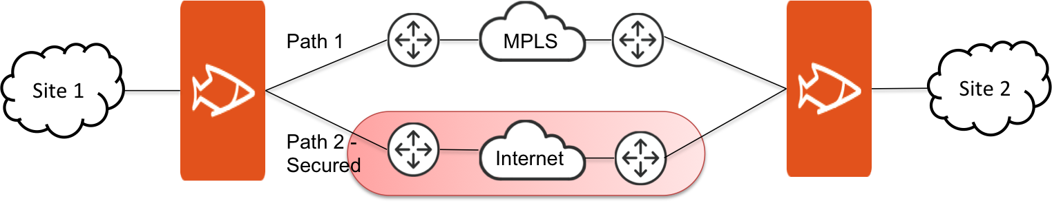
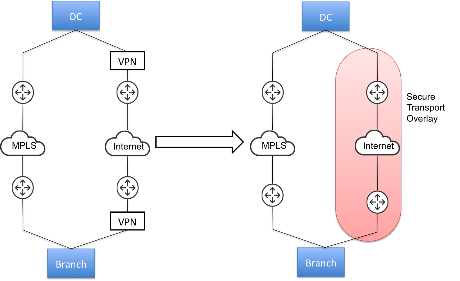
With broader adoption of public WAN services to supplant private resources, hybrid networks are becoming more common as they combine the strengths of the highly reliable MPLS with the lower-cost Internet infrastructure. A hybrid network, when controlled by path selection, combine the private WAN and public Internet to increase available bandwidth, application performance, and network reliability at the lowest cost possible. Secure transport data protection and path selection allow organizations to have the benefits of a hybrid network without the underlying complexity.
Direct-to-net public access requires a higher degree of security at the branch than a private WAN. Unlike traffic sent across a private WAN to access data center resources, public Internet transport requires all traffic to be encrypted and protected. Encryption of data over private WAN connections is also beneficial for ensuring that traffic is secure end-to-end (that is, protected as it traverses the last mile over various service provider networks). While managed service providers can offer secure VPN services, the cost of service and trust concerns make customer managed solutions preferred. With secure transport you can retain control over confidentiality of data.
Consider these guidelines when you configure secure transport:
•Secure transport requires an SSL license. Due to export control of encryption, each SteelHead is required to have an SSL license before in can join the secure transport group. For detailed information about verifying SteelHead licenses, see the
SteelHead User Guide. If you don’t have a valid enhanced cryptography license key file, follow the procedures documented here:
https://sslcert.riverbed.com. •You must configure networks and sites before you begin configuring secure transport. When you define networks, you specify which networks are secure. For details, see
“Defining networks” on page 182. •Traffic is double encrypted only when both secure transport and SSL secure peering are enabled.
•Only physical in-path deployments are supported; virtual in-path deployments aren’t supported.
•In RiOS 9.0 or later, IPsec secure peering and the secure transport service are mutually exclusive.
•The secure transport service is enabled by default on SteelHeads. Before you enable IPsec secure peering on the SteelHead, you must disable the secure transport service on the SteelHead.
•Flow statistic collectors, such as NetFlow, can’t collect Encapsulating Security Payload (ESP) packet data flow information.
•SteelHeads must be present on both endpoints of the path.
Common network deployment models for secure transport
Secure transport is designed to provide security to any uplink: for example, internet facing links. This is achieved through leveraging path selection. Path selection provides you with the ability to control the paths on which their applications flow. Secure transport defines encryption as an attribute to the path defined in path selection. By doing so, any application that chooses a secure path is encrypted. Secure transport provides encryption services to both WAN optimized traffic and all other traffic matched by the path selection services policy.
Secured transport
With secure transport, the most common network deployment models are:
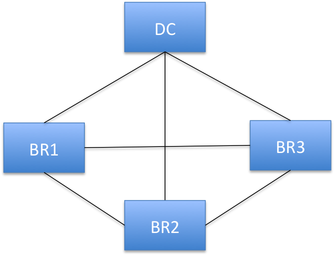
•Full mesh - The mesh model is one in which branches are connected with many redundant interconnecting circuits between them. In a mesh model if any circuit or node fails, there are many other ways for two branches to communicate. In a full mesh model every branch has a circuit connecting it to every other branch in a network. A mesh connected network is preferred by latency sensitive peer to peer applications, such as UCC (unified communication and collaboration). Peer-to-peer as well as peer-to-branch communication models are fully supported by secure transport. Each peer is allowed to securely exchange traffic with any other peer without having to go through the data center peer (hub).
Full mesh
•Hybrid-Backhaul-Existing - Here you already have two circuits between the data center and the branch. A third-party dedicated MPLS link with no security enabled on it, and other is an Internet link. There is probably an third party VPN device after the SteelHead on the Internet path to provide reachability and security on that link. Now, you can remove this VPN device and enable secure transport on internet paths defined in path selection. This way the SteelHead can select the path based on policies for application and apply security to the traffic traversing the internet link.
Hybrid-backhaul-existing
Typical workflow for configuring secure transport
These steps represent a typical workflow for configuring secure transport.
1. Due to export control of encryption, each SteelHead is required to have an SSL license before in can join the secure transport group. For detailed information about verifying SteelHead licenses, see the
SteelHead User Guide. If you don’t have a valid enhanced cryptography license key file, follow the procedures documented here:
https://sslcert.riverbed.com. 3. Define application policies. Based on your defined application policies, the SCC enables you to prioritize, secure, and deliver critical applications over the faster networks. For details, see
“Defining applications” on page 373. 6. Add appliances to the secure transport group. All appliances that have a securable uplink are added automatically to a secure transport group. For details, see
“Managing path selection” on page 329. Configuring the secure transport controller on the SteelHead
A secure transport controller is a centralized service deployed on a reachable SteelHead. The SteelHead typically resides in the data center and manages the control channel and operations required for secure transport between SteelHead peers. The control channel between the SteelHeads uses SSL to secure the connection between the peer SteelHead and the SteelHead secure transport controller.
The secure transport controller controls and manages secure transport key generation, distribution of local site subnets and rekeying between secure transport peers, and uses a centralized portal for configuring and reporting.
The secure transport controller must be reachable by other SteelHead peers. You must enable secure transport client on all the SteelHead peers in which you want secure transport to encrypt data. On the SCC, all appliances that have a securable uplink are added to a secure transport group.
You can have only one active secure transport controller in your deployment. You can view secure transport properties for a SteelHead configured as a secure transport peer in the Secure Transports report on the SteelHead. For detailed information about the Secure Transports report, see the SteelHead User Guide for SteelHead CX.
Disconnected mode
When connectivity is lost between the secure transport controller and its peers, the peers go into disconnected mode. The last known keys and subnet information are used during the Disconnected mode Timeout period.
An alarm is raised on the SteelHead peer when it enters disconnected mode. For detailed information about the secure transport alarm on SteelHeads, see the Alarm Status report on the SteelHead in the SteelHead User Guide for SteelHead CX. Possible causes for a disconnected mode timeout are:
•Connection with Controller Lost - Indicates that the peer SteelHead is no longer connected to the SteelHead secure transport controller for one of these reasons:
–The connectivity between the peer SteelHead and the SteelHead secure transport controller is lost.
–The SSL for the connection isn’t configured correctly.
•Registration with Controller Unsuccessful - Indicates that the peer SteelHead isn’t registered with the SteelHead secure transport controller, and the controller doesn’t recognize it as a member of the secure transport group.
After a disconnected mode timeout (which can be configured through the SCC), all secure transport tunnels are brought down.
To configure the secure transport controller on the SteelHead
1. Log in to the CLI on the SteelHead that you want to configure as the secure transport controller. For detailed information about connecting to the CLI, see the Riverbed Command-Line Interface Reference Manual.
2. Enter configuration mode and run these CLI commands:
sh2 (config) # stp-controller address private-ip <private-ip-address> public-ip <public-ip-address> port <port-number>
sh2 (config) # stp-controller enable
sh2 (config) # show stp-controller status
Secure Transport Controller status: Enabled
sh2 (config) # show stp-controller address
Controller Properties:
Private address: 10.0.0.1
Public address: 10.0.0.2
private-ip <private-ip-address> | Specifies an IP address that’s bound to the management interface of the SteelHead that you have chosen to be the secure transport controller. The secure transport controller IP address can be bound to an in-path address if management over the in-path interface is enabled (that is, the SteelHead is managed via the in-path address). |
public-ip <public-ip-address> port <port-number> | Optionally, specifies a publicly reachable IP address and port that’s NATed to the management interface on the SteelHead running the secure transport controller. |
Activating the secure transport controller on the SCC
You activate the secure transport controller on the SCC in the Secure Transport page.
To activate the secure transport controller on the SCC
2. Choose > Manage > Services: Secure Transport to display the Secure Transport page.
3. Under Active Secure Transport Controller, select the name of the secure transport controller you want to activate and click Make Active.
Activating a secure transport controller
Adding appliances to the secure transport group
The secure transport group is a set of SteelHeads that share the same cryptographic keys and have connectivity to each other. Any member of the secure transport group can create a secure path to any other member of the same group instantaneously, without delay. The traffic doesn’t incur any added latency waiting for the secure paths to establish, as is common with traditional IPsec VPNs.
All appliances that have a securable uplink are automatically added to a secure transport group.
To ensure your network is secure for use with secure transport:
•Select Securable using Secure Transport when you add networks to your topology. For details, see
“Defining networks” on page 182. If the network represents the Internet, select Public Network; public networks are UDP encapsulated.
•If the secure network is newly created, then all appliances belonging to the sites that use the securable uplink going forward will be added to the secure transport group. If the network already exists, you can edit it to make it secure, then all appliances belonging to existing sites using that uplink will be added to the secure transport group.
•Associating a secure uplink to the site makes all appliances of that site a part of secure transport mesh.
•All uplinks and thereby all paths derived from a secure network are handled by secure transport.
To ensure that appliances are part of the secure transport group
1. Choose Manage > Topology: Sites & Networks to display the Sites & Networks page.
2. Click + Add a Network to display the New Network pop-up window.
Adding a network
3. Specify a network name: for example doctest, select Securable using Secure Transport to ensure that the network is part of the secure transport group, and click Save.
4. Under Sites, select the site you want to associate with the secure network and click Edit Site to display the Edit a Site pop-up window. To associate a new site click + Add a Site to display the Edit a Site pop-up window and specify the site name, type, and region.
5. Under Uplinks, click
+ Add a New Uplink and select the secured network from the Network drop-down list. Define the remaining parameters for the uplink. For details, see
“Defining uplinks” on page 205. Associating the secure network to an uplink
6. Click Save to save your settings.
Configuring secure transport group settings
All appliances that require a secure uplink are added to a secure transport group automatically. You can secure traffic flowing between any two appliances in the group by directing it to a secured uplink using path selection service rules. All appliances that have a secure uplink are added to a secure transport group during site and network creation.
You configure the secure transport group settings in the Secure Transport page.
To configure secure transport group settings
1. Choose > Manage > Services: Secure Transport to display the Secure Transport page.
Configuring secure transport group settings
2. Under Group Settings, complete the configuration as described in this table.
Control | Description |
Rekey Interval | Specify the time in seconds to rekey the group. This is the number of seconds after which the secure transport controller will generate new security keys and push them out to the secure transport members. The secure transport members will then start using the new keys for encrypting the traffic. The default value is 3600. |
Rekey Data Size | Specify the rekey data size in megabytes. The rekey data size is the total data size encrypted by all peers using a certain security key after which the secure transport controller should generate a new key and push it to the secure transport members. The default value is 4194304. |
Disconnected Mode Timeout | Specify the amount of time in seconds the secure transport members can operate while disconnected from the secure transport controller. The default value is 300. After a disconnected mode timeout, all secure transport paths are brought down. Make sure you allow enough time for the group to recover from a disconnected state. |
Authentication Algorithm | Displays the authentication algorithm is displayed for informational purposes. |
Encryption Algorithm | Displays the encryption algorithm is displayed for informational purposes. |
Save and Apply/Revert | Click Save and Apply to save and apply your settings; click Revert to undo your changes. |
Viewing active secure transport status
You can view the current status of active secure transport controller in the Secure Transport page.
To view the current status of the active secure transport controller
1. Choose > Manage > Services: Secure Transport to display the Secure Transport page.
2. Under Active Secure Transport Status, to view the current status of the active secure transport controller.
Viewing active secure transport controller status
3. Click Rekey Now to rekey all SteelHead peers in the group.
Viewing group traffic information
You can view group traffic information in the Secure Transport page.
To view group traffic information
1. Choose > Manage > Services: Secure Transport to display the Secure Transport page.
2. Under Traffic Information for Default_Group, view group traffic information.
Viewing group traffic information
3. Click the From and To text boxes to display a calendar to set the time to begin and end the traffic information to be displayed.
4. Click Update to update the traffic information.
Viewing secure group members
You can view the members of the secure transport group in the Secure Transport page.
To view members of the secure transport group
1. Choose > Manage > Services: Secure Transport to display the Secure Transport page.
Under Secure Members, view the members of the group. A green dot next to the member name indicates a connected secure transport controller; a red dot next to the member name indicates a disconnected secure transport controller.
Viewing members of the secure transport group
2. Optionally, in the Filter text box type a set of criteria by which to filter the displayed members.
Managing QoS
You enable QoS and configure QoS profiles in the Quality of Service page. This section contains these topics:
QoS overview
QoS is a reservation system for network traffic. In its most basic form, QoS allows organizations to allocate scarce network resources across multiple traffic types of varying importance. Advanced QoS implementations allow organizations to accurately control their applications by the amount of bandwidth they have access to and by their sensitivity to delay.
QoS configuration identifies business applications and classifies traffic according to priorities. The SteelHead uses this information to control the amount of WAN resources that each application can use. QoS ensures that your important applications are prioritized and removes the guesswork from protecting performance of key applications. In addition, QoS can prevent recreational applications from interfering with business applications. Before configuring QoS, we recommend that you define any custom applications for use in QoS profiles. For details, see
“Defining applications” on page 373. We recommend that you configure and push QoS policies from SCC to the SteelHeads, particularly with large scale deployments. With an SCC and SteelHeads running 9.2 and later, if you have path selection disabled and QoS enabled, the SCC pushes settings to only those remote sites which are applicable to the local site. If you’re running SCC 9.2 and later, if you push QoS settings to SteelHeads running RiOS 9.1 and 9.0, the push might fail.
For detailed information about configuring QoS for SteelHeads, including legacy QoS configuration features and requirements, see the SteelHead User Guide for SteelHead CX.
For detailed information about deploying QoS in your network, see the SteelCentral Controller for SteelHead Deployment Guide.
Enabling and disabling QoS
You can enable global QoS for your network deployment or you can disable QoS at certain sites in the Quality of Service page.
To enable global QoS
1. Choose Manage > Services: Quality of Service to display the Quality of Service page.
Enabling QoS
2. Complete the configuration as described in this table.
Control | Description |
Enable QoS for SteelHeads running RiOS 9.0 or greater | Select to enable QoS on SteelHeads running RiOS 9.0 or later. |
Enable Outbound QoS | Enables QoS classification to control the prioritization of different types of network traffic and to ensure that the SteelHead gives certain network traffic (for example, Voice over IP) higher priority than other network traffic. Traffic isn’t classified until at least one WAN interface is enabled. The system enables inbound and outbound QoS on all in-path interfaces by default. For detailed information about outbound QoS, see the SteelHead User Guide for SteelHead CX. |
Enable Inbound QoS | Enables QoS classification to allocate bandwidth and prioritize traffic flowing into the LAN network behind the SteelHead. Inbound QoS provides the benefits of QoS for environments that can’t meet their QoS requirements with outbound QoS. Enabling inbound QoS focuses on prioritizing types of traffic using rules and classes just like outbound QoS. The inbound configuration is separate from the outbound configuration. You define the applications on the local network and then create their corresponding shaping policies. For detailed information about inbound QoS, see the SteelHead User Guide for SteelHead CX. |
Enable DSCP Marking | Select to enable DSCP marking. You must select DSCP values if the service providers are applying QoS metrics based on DSCP marking and each provider is using a different type of metric. |
Save | Click Save to save and apply your settings; click Revert to undo your changes. |
To disable QoS at sites
3. Choose Manage > Services: Quality of Service to display the Quality of Service page.
4. Click Disable QoS at Certain Sites to expand the page.
5. Click + Add an override to display the New QoS Override pop-up window.
Disabling QoS
6. Complete the configuration as described in this table.
Control | Description |
Select Site or Site Type | Select Site or Site Type on which to disable QoS. Click the text box to display a drop-down list with the sites or site types from which to choose. |
Disable Outbound QoS | Select to disable outbound QoS on the site or site type. |
Disable Inbound QoS | Select to disable inbound QoS on the site or site type. |
Disable DSCP Marking | Select to disable DSCP marking on the site or site type. |
Disable QoS per Interface | Click the > to display the inbound and outbound QoS interfaces. Select the interfaces to disable QoS on the interface. |
Save/Revert | Saves your settings; click Revert to undo your changes. |
Adding a QoS profile
In SCC 9.0 or later, QoS profiles replace QoS policies. To use QoS, you must create sites and site types before using QoS. For details, see
“Migrating appliances to sites” on page 213.A QoS profile is a container for QoS rules and QoS classes that apply to a source and destination site, or site type, or any site. When you push QoS profiles, only the selected sites or site types in the push are assigned to the applied QoS profiles. You can have multiple source and destination sites in a QoS profile.
A QoS profile defines the endpoints to which the QoS profile will apply. Specifically, it defines the source and destination sites or site types or any site that this QoS profile applies to. When you create QoS profiles, we recommend you select site types rather sites to make QoS rules more manageable. You should only select sites when you create exceptions in QoS profiles containing the site types. You can create a blank profile and copy settings from existing profiles. We recommend you copy from existing QoS profiles when most of the QoS profile configuration is the same and you only need to change a few settings. For details, see
“Adding classes and rules to QoS profiles” on page 357.You can create up to three levels of a class hierarchy in a QoS profile. For any additional class levels, you must use the CLI on the SteelHead. For detailed information about the CLI command, see the Riverbed Command-Line Interface Reference Manual.
When you build the QoS profile on the SCC, assigning a QoS profile name enables you to identify which profile goes to which SteelHead. It also enables you to reuse the QoS profile as a template by renaming it. You can also define which sites or interfaces to be excluded from a QoS profile.
The default QoS profile (that is, Any Site to Any Site) has a class structure and a default QoS rule. By default, all in-path interfaces are enabled for inbound and outbound QoS with the same link rate. The default profile is important because it is the profile that takes the bulk of the traffic. Use the default profile to capture traffic from any site to any site. You can edit the default QoS profile but you can’t delete it.
QoS rules should also use application groups rather than individual applications. Application groups enable you to manage QoS rules in a simpler way. You should only use individual applications in QoS rules to create exceptions for QoS rules. For detailed information about configuring application groups, see
“Configuring application groups using the path selection wizard” on page 330. In SCC 9.0 and later, support for inbound and outbound QoS reports for SteelHeads running RiOS 9.0 and later has been dropped. To view these reports, you must connect to the individual SteelHead.
To add a QoS profile
1. Choose Managing > Services: Quality of Service to display the Quality of Service page.
2. Click + Add a QoS Profile to display the New QoS Profile pop-up window.
Adding a new QoS profile
3. Complete the configuration as described in this table.
Control | Description |
Name | Specify a name that describes this profile. Click the text box to display a drop-down list of sites or site types from which to choose. The option Any Site doesn’t display choices as it includes all sites. When you create QoS profiles, we recommend selecting site types rather sites to make QoS more manageable. Sites should only be selected when creating exceptions for QoS profiles containing the site types. When you push QoS profiles, only the selected site types or sites in the push are applied to the QoS profiles. Each profile can have multiple source and destinations defined. With multiple source and destination sites, you can reuse an existing QoS profile at a site or quickly change a single site to a QoS profile. |
Classes and Rules | Select one of these options: •Create Blank Profile with No Classes or Rules to create an empty profile. •Copy Classes and Rules from Existing Profile to copy an existing profile. Click the text box to display a drop-down list that displays the default and custom profiles. The autocomplete shows existing QoS profile names. The Any Site to Any Site profile is the default profile and applies to all sites. If you select this option, you can’t create another profile of this type. For example, you could create these types of profiles: •Branch to Data Center - Creates a profile that’s applicable only to branch and data center sites. •Any Site to Branch - Creates a profile that’s applicable to all sites connecting to the branch. •Headquarters to Any Site - Creates a profile that’s applicable to all sites connecting to the headquarters. |
Sites | Select a site or site type (for example, Any Site, Data Center, Headquarters, or Branch) as the Source (outbound) and Destination (inbound) sites for this profile. Click Add Site to configure multiple source and destinations sites. With multiple source and destination sites, you can reuse an existing QoS profile at a site or quickly change a single site to a QoS profile. |
Create Profile | Saves your profile settings. |
To view a profile
1. Choose Managing > Services: Quality of Service to display the Quality of Service page.
2. Under QoS Profiles, click Edit QoS Profile next to the name of the profile you want to view and display the QoS Profile Details page.
Displaying the QoS profile
The profile name, rules, and classes appear. The classes model the network requirements for applications that exhibit similar characteristics and have similar requirements: minimum bandwidth, maximum bandwidth, and latency priority. For example, the Realtime class contains voice and video traffic.
A QoS profile contains one or more classes. Classes within a profile are typically organized in a hierarchical tree structure.
Adding classes and rules to QoS profiles
You edit a QoS profile and add classes and rules in the Quality of Service: QoS Profile Details page. This section includes these topics:
A QoS profile is a self-contained set of QoS classes and rules that’s used to control communication from a source sites to destination sites.
You can create a tree structure using classes within a profile that contains children of class parents. Use a hierarchical tree structure to:
•segregate traffic based on flow source or destination and apply different shaping rules to each child.
•effectively manage and support remote sites with different bandwidth characteristics.
Before you begin creating QoS profiles, you must:
•Create sites, site types, networks, uplinks, and uplink types. You can select a profile to reuse the set of QoS classes and rules for multiple sites. For details about sites, see
“Managing Interceptor clusters” on page 304. •Plan which profiles will apply to source and destination sites. You can configure multiple source and destination sites and site types in a QoS profile. With multiple source and destination sites and site types, you can reuse an existing QoS profile at a site.
When you create QoS profiles, we recommend selecting site types rather sites to make QoS more manageable. Sites should only be selected when creating exceptions for QoS profiles containing the site types. When you push QoS profiles, only the selected site types or sites in the push are applied to the QoS profiles.
Modifying QoS profiles
You can modify a QoS profile in the QoS Profile Details page. You can rename a profile name, class, or rule seamlessly without the need to manually update the associated resources. For example, if you rename a profile associated with a site, the system updates the profile name and the profile name within the site definition automatically.
Classifying and prioritizing out-of-band traffic using DSCP marking
RiOS 9.1 provides a way to separate the inner channel setup packets from the OOB packets and mark the OOB control channel traffic with a unique DSCP value. The SteelHeads use the OOB connection to exchange capabilities and feature information such as licensing, hostname, RiOS version, and so on. The SteelHeads also use control channel information to detect failures. For detailed information, see the SteelHead User Guide for SteelHead CX.
You can mark OOB connections with a DSCP or ToS IP value to prioritize or classify the Riverbed control channel traffic, preventing dropped packets in a lossy or congested network to guarantee control packets will get through and not be subject to unexpected tear down. As part of the upgrade and installation process, SCC 9.1 automatically creates a global policy called Riverbed Global Policy with port labels that contain the necessary applications to configure DSCP.
Before marking OOB traffic with a DSCP value, ensure that the global DSCP setting isn’t in use. Global DSCP marking includes both inner channel setup packets and OOB control channel traffic. This procedure separates the OOB traffic from the inner channel setup traffic. For details on turning off global DSCP marking, see the [no] qos dscp-marking enable command in the Riverbed Command-Line Interface Reference Manual.
When you add a QoS rule, under Application or Application group, you select the Riverbed Control Traffic (Client) application if the SteelHead being configured is a client-side SteelHead, then select the Riverbed Control Traffic (Server) application if the SteelHead being configured is a server-side SteelHead.
OOB packets are marked on the server-side SteelHead based on the value configured on client-side SteelHead if a rule isn’t explicitly configured on the server-side SteelHead.
To add a rule to a QoS profile
1. Choose Managing > Services: Quality of Service to display the Quality of Service page.
2. Under QoS Profiles, click Edit QoS Profile next to the profile name to display the QoS Profile Details page.
Displaying QoS profile details
3. Under Affected Sites, click Edit to display the New QoS Profile pop-up window.
Editing a site in a QoS profile
4. Complete the configuration as described in this table.
Control | Description |
Name | Specify a name that describes this profile. Click the text box to display a drop-down list of sites or site types from which to choose. The option Any Site doesn’t display choices as it includes all sites. When you create QoS profiles, we recommend selecting site types rather sites to make QoS more manageable. Sites should only be selected when creating exceptions for QoS profiles containing the site types. When you push QoS profiles, only the selected site types or sites in the push are applied to the QoS profiles. Each profile can have multiple source and destinations defined. With multiple source and destination sites, you can reuse an existing QoS profile at a site or quickly change a single site to a QoS profile. |
Classes and Rules | Select Create Blank Profile with No Classes or Rules to create an empty profile. Select Copy Classes and Rules from Existing Profile to copy an existing profile. Click the text box to display a drop-down list that displays the default and custom profiles. The autocomplete shows existing QoS profile names. These default profiles are available: •Any Site to Any Site - Creates a profile that applies to all sites. If you select this option, you can’t create another profile of this type. •Branch to Data Center - Creates a profile that’s applicable only to branch and data center sites. •Any Site to Branch - Creates a profile that’s applicable to all sites connecting to the branch. •Headquarters to Any Site - Creates a profile that’s applicable to all sites connecting to the headquarters. |
Sites | Select Any Site, Data Center, Headquarters, or Branch as the Source (outbound) and Destination (inbound) sites for this profile. Click Add Site to configure multiple source and destinations sites. With multiple source and destination sites, you can reuse an existing QoS profile at a site or quickly change a single site to a QoS profile. |
Create Profile | Saves your profile settings. |
Adding a class to a QoS profile
You add classes to QoS profiles in the QoS Profile Details page.
QoS classes model the network requirements for applications that exhibit similar characteristics and have similar requirements: minimum bandwidth, maximum bandwidth, and latency priority. For example, the Realtime class contains voice and video traffic. A QoS profile contains one or more classes. Classes within a profile are typically organized in a hierarchical tree structure.
To add a class to a QoS profile
1. Choose Managing > Services: Quality of Service to display the Quality of Service page.
2. Under QoS Profiles, click Edit QoS Profile next to the profile name to display the QoS Profile Details page.
Displaying QoS profile details
3. Under QoS Classes, click Edit to expand the page and click + Add Class to display the New Class pop-up window.
Configuring a class
4. Complete the configuration as described in this table.
Control | Description |
Class Name | Specify a name for the QoS class. |
Minimum Bandwidth | Specify the minimum amount of bandwidth (as a percentage) to guarantee to a traffic class when there is bandwidth contention. All of the classes combined can’t exceed 100 percent. During contention for bandwidth, the class is guaranteed the amount of bandwidth specified. The class receives more bandwidth if there is unused bandwidth remaining. Excess bandwidth is allocated based on the relative ratios of minimum bandwidth. The total minimum guaranteed bandwidth of all QoS classes must be less than or equal to 100 percent of the parent class. A default class is automatically created with minimum bandwidth of 10 percent. Traffic that doesn’t match any of the rules is put into the default class. we recommend that you change the minimum bandwidth of the default class to the appropriate value. You can adjust the value as low as 0 percent. The system rounds decimal numbers to 5 points. |
Maximum Bandwidth | Specify the maximum allowed bandwidth (as a percentage) a class receives as a percentage of the parent class maximum bandwidth. The limit is applied even if there is excess bandwidth available. The system rounds decimal numbers to 5 points. |
Queue | Optionally, select one of these queue methods for the leaf class from the drop-down list (the queue doesn’t apply to the inner class): •SFQ - Shared Fair Queueing (SFQ) is the default queue for all classes. Determines SteelHead behavior when the number of packets in a QoS class outbound queue exceeds the configured queue length. When SFQ is used, packets are dropped from within the queue in a round-robin fashion, among the present traffic flows. SFQ ensures that each flow within the QoS class receives a fair share of output bandwidth relative to each other, preventing bursty flows from starving other flows within the QoS class. •FIFO - Transmits all flows in the order that they’re received (first in, first out). Bursty sources can cause long delays in delivering time-sensitive application traffic and potentially to network control and signaling messages. •MX-TCP - Has very different use cases than the other queue parameters. MX-TCP also has secondary effects that you must understand before configuring: –When optimized traffic is mapped into a QoS class with the MX-TCP queueing parameter, the TCP congestion-control mechanism for that traffic is altered on the SteelHead. The normal TCP behavior of reducing the outbound sending rate when detecting congestion or packet loss is disabled, and the outbound rate is made to match the guaranteed bandwidth configured on the QoS class. –You can use MX-TCP to achieve high-throughput rates even when the physical medium carrying the traffic has high-loss rates. For example,
MX-TCP is commonly used for ensuring high throughput on satellite connections where a lower-layer-loss recovery technique isn’t in use. RiOS 8.5 and later introduce rate pacing for satellite deployments, which combines MX-TCP with a congestion-control method. –Another use of MX-TCP is to achieve high throughput over high-bandwidth, high-latency links, especially when intermediate routers don’t have properly tuned interface buffers. Improperly tuned router buffers cause TCP to perceive congestion in the network, resulting in unnecessarily dropped packets, even when the network can support high-throughput rates. MX-TCP is incompatible with AFE identification. A traffic flow can’t be classified as MX-TCP and then subsequently classified in a different queue. This reclassification can occur if there is a more exact match of the traffic using AFE identification. You must ensure these best practices when you enable MX-TCP: – The QoS rule for MX-TCP is at the top of QoS rules list. – The rule doesn’t use AFE identification. – You only use MX-TCP for optimized traffic. MX-TCP doesn’t work for unoptimized traffic. |
| Use caution when specifying MX-TCP. The outbound rate for the optimized traffic in the configured QoS class immediately increases to the specified bandwidth, but it doesn’t decrease in the presence of network congestion. The SteelHead always tries to transmit traffic at the specified rate. If no QoS mechanism (either parent classes on the SteelHead, or another QoS mechanism in the WAN or WAN infrastructure) is in use to protect other traffic, that other traffic might be impacted by MX-TCP not backing off to fairly share bandwidth. •There is a maximum bandwidth setting for MX-TCP that allows traffic in the MX class to burst to the maximum level if the bandwidth is available. For detailed information about MX-TCP Queue Policies, see the SteelHead User Guide for SteelHead CX. |
DSCP | Selects the default DSCP mark for the class. QoS rules can then specify Inherit from Class for outbound DSCP to use the class default. Select Preserve or a DSCP value from the drop-down list. This value is required when you enable QoS marking. The default setting is Preserve, which specifies that the DSCP level or IP ToS value found on pass-through and optimized traffic is unchanged when it passes through the SteelHead. The DSCP marking values fall into these classes: •Expedited forwarding (EF) class - In this class, packets are forwarded regardless of link share of other traffic. The class is suitable for preferential services requiring low delay, low packet loss, low jitter, and high bandwidth. •Assured forwarding (AF) class - This class is divided into four subclasses, each containing three drop priorities for more granular classification. The QoS level of the AF class is lower than that of the EF class. •Class selector (CS) class - This class is derived from the IP ToS field. |
Priority | Select a latency priority from 1 through 6, where 1 is the highest and 6 is the lowest. |
Save/Revert | Saves your settings; Click Revert to clear the controls. |
x | Click to remove the class. To remove a parent class, delete all rules for the corresponding child classes first. When a parent class has rules or children, the x for the parent class is unavailable. |
5. The QoS classes appear in the profile. To display QoS rules associated with the class, select the QoS profile.
To add a child class to a parent class
1. Click Edit QoS Profile next to the profile name to display to the QoS Profile Details page.
2. To the right of the parent class, click
+ Add Class to display the New Class pop-up window. For detailed information about the class parameters, see
“To add a QoS profile” on page 354. Adding a class
3. Complete the child class definition and click Add Class and Save to save your settings. You can add up to three children classes belonging to one parent class.
Adding rules to a QoS profile
You add rules to a QoS profile in the QoS Profile Details page.
Each rule maps a type of network traffic to a QoS profile. You can create multiple QoS rules for a profile. When multiple QoS rules are created for a profile, the rules are followed in the order in which they’re shown in the QoS Profile table and only the first matching rule is applied to the profile. SteelHeads support up to 2000 rules and up to 200 sites. When a port label is used to add a QoS rule, the range of ports can’t be more than 2000 ports.
To add a rule to a QoS profile
1. Choose Managing > Services: Quality of Service to display the Quality of Service page.
2. Under QoS Profiles, click Edit QoS Profile next to the profile name to display the QoS Profile Details page.
Displaying QoS profile details
3. Under QoS Rules, click + Add a Rule to display the New Rule pop-up window.
Adding a rule to a QoS profile
4. Complete the configuration as described in this table.
Control | Description |
Application or Application Group | Specify the application or application group. We recommend using application groups for the easiest profile configuration and maintenance. Type the first few letters of the application or application group in the text box. As you type the name, a drop-down list appears that lists available applications or groups that match your entry. Select an application or group from the list. |
QoS Class | The QoS class indicates how delay sensitive a traffic class is to the QoS scheduler. Select a service class for the application from the drop-down list (highest priority to lowest): •Inherit from Default Rule - Uses whichever class is currently set for the default rule. By default, this is Low Priority. •Real-Time - Specifies real-time traffic class. Give this value to your highest priority traffic: for example, VoIP, or video conferencing. •Interactive - Specifies an interactive traffic class: for example, Citrix, RDP, telnet, and SSH. •Business Critical - Specifies the high priority traffic class: for example, Thick Client Applications, ERPs, and CRMs. •Normal Priority - Specifies a normal priority traffic class: for example, Internet browsing, file sharing, and email. •Low Priority - Specifies a low priority traffic class: for example, FTP, backup, replication, other high-throughput data transfers, and recreational applications such as audio file sharing. •Best Effort - Specifies the lowest priority. These are minimum service class guarantees; if better service is available, it is provided. For example, if a class is specified as low priority and the higher priority classes aren’t active, then the low priority class receives the highest possible available priority for the current traffic conditions. This parameter controls the priority of the class relative to the other classes. Note: The service class describes only the delay sensitivity of a class, not how much bandwidth it is allocated, nor how important the traffic is compared to other classes. Typically you configure low priority for high-throughput, nonpacket delay sensitive applications like FTP, backup, and replication. |
DSCP Mark | Select Inherit from Class, Preserve, or a DSCP value from the drop-down list. This value is required when you enable QoS marking. The default setting is Inherit from Class. Preserve specifies that the DSCP level or IP ToS value found on pass-through and optimized traffic is unchanged when it passes through the SteelHead. When you specify a DSCP marking value in a rule, it either takes precedence over or inherits the value in a class. |
Add/Revert | Click Add to add your changes; click Revert to clear your settings. |
Pushing your settings and viewing push status
You can push your QoS profiles to SteelHeads from the Policy Push Control on the right side of the page. You can also view push status from the Push Status panel on the right side of the page.
If the SCC and SteelHeads are both running 9.2 and later, for the initial configuration the SCC pushes the entire configuration. For SteelHeads and an SCC running 9.2 and later, any changes made after the initial push, the SCC pushes only the modified settings to ensure improved response times and throughput performance. If the SCC and SteelHeads are both running 9.0 and 9.1, when you push configuration changes, whether the initial push or after, the SCC deletes the entire configuration and replaces it with the new configuration settings, which can slow response times and performance.
When you perform a policy push, the SCC is the master configuration; any local changes made on SteelHeads are overwritten.
To push settings
1. Under Policy Push Control on the right side of the page, click Include in Push to expand the page and display the Push to Appliances panel.
Pushing settings
To exclude appliances from the push, under Push Control on the right side of the page, click Exclude from Push. (This option only appears if you have clicked Include in Push.)
2. Complete the configuration as described in this table.
Control | Description |
Push to Appliances | Select to push your path selection rules: •Site Types - Click the text box to display site types to choose from. Select the site types one at a time to add them to the text box. After you select the site type, it is displayed in the text box. To remove a site type, click the X. To view what sites make up the site type, click See More. We recommend that you choose site types rather than sites to organize your rules as site types make the management of rules easier. •Sites - Click the text box to display sites to choose from. Select the sites one at a time to add them to the text box. After you select the site, it is displayed in the text box. To remove a site, click the X. To view site details, click See Details. |
Push All | Pushes all related configurations, such as applications, sites, and networks. |
Push Only QoS Configuration | Pushes only QoS configuration settings to remote appliances. |
Push | Pushes configuration settings to the selected sites or site types. Click Clear to clear your settings. |
Viewing push status
You can view the current status of your pushes on the right side of the page in the Push Status panel.
To view current status of configuration pushes
•Under Push Status on the right side of the page, click More to be directed to the Operation History page.
Displaying push status
The current operations (that is, pushes) and status are displayed in the Operations table.
Migrating legacy QoS policies
The SCC enables you to migrate your legacy policies (basic and advanced) to QoS profiles using a migration wizard.
You must perform these prerequisite steps before beginning the migration wizard:
•Include the basic and advanced legacy policies in the push.
•You’re encouraged to create a copy of your policies before you migrate so that you can undo the operation.
The migration wizard uses the existing assigned legacy policy rules. These rules are included in legacy policy pushes to give you the various choices for the QoS profiles. You might have to wait for approximately five minutes before starting the migration if there are any changes made to the legacy policy.
The migration is a bulk migration—migrating a legacy policy can result in more than one QoS profile being created. The migration doesn’t affect the existing legacy QoS policy. These legacy policies continue to be apply to SteelHeads running RiOS later than 9.0.
For detailed best practices regarding migrating QoS policies to profiles, see
“QoS migration” on page 67.To migrate an outbound legacy (basic or advanced) QoS policy
1. Choose Manage > Services: Quality of Service to display the Quality of Service page.
Migrating a QoS policy
2. Under QoS Profiles, click Migrate Legacy QoS Policies to display the QoS migration wizard.
3. Select the legacy outbound QoS policy you want to migrate and click Migrate to display the Source Site Selection page.
4. Select the source site for the new QoS profile.
The Any Site option creates the fewest number of QoS rules, which makes profiles easier to manage. This setting might change the QoS behavior for sites that didn’t have this legacy QoS policy assigned.
A warning message is displayed if any appliances that are assigned to this legacy QoS policy aren’t assigned to a site. QoS requires all appliances to be assigned to sites or site types. For details about creating sites and site types, see
“Managing Interceptor clusters” on page 304.5. Click Next to display the Service Policy Selection page.
Service policies in legacy basic QoS policy translate into a class structure in the current QoS.
6. Select the service policy and click Choose to display the Destination Site Selection page.
7. Choose the destination site or site type for the new QoS profile.
This action might result in a large number of QoS profiles and can make QoS management difficult. The Any Site option creates the fewest number of QoS profiles, which makes QoS easier to manage. This setting might change the QoS behavior for sites that didn’t have this legacy QoS policy assigned.
Click Show Site to view the type of site in a pop-up window.
8. Select Site and Next to maintain current site and site type relationships.
9. Click Next to display the Migration Confirmation page and review the current settings for the migration. Click Back to return to previous pages.
To view legacy appliance policy details, click the appliance name to display the Editing Policy: <appliance>, Outbound QoS (Basic) page.
10. Click Migrate Now to migrate your legacy QoS policy.
To view legacy appliance policy details, click the appliance name to display the Editing Policy: <appliance>, Outbound QoS (Basic) page.
Managing application policies
This section describes how to define and manage applications. This section includes these topics:
Defining applications
You can view application groups and add custom applications in the Applications page. We recommend that you define applications and push statistics collection from the SCC to SteelHeads. The SCC application library contains more than 1900 applications.
Tip: You can search for applications using the search bar from any page within the SCC. If you type at the first few letters of the application a drop-down list appears listing all applications beginning with those letters. For example, if you type fac in the search bar a drop-down list appears listing all the applications that begin with fac. The search isn’t limited to applications, it also lists sites, QoS profiles, and so forth.
For detailed information about QoS rules, see
“Adding rules to a QoS profile” on page 366. To view applications by application group
2. Choose Manage > App Definitions: Applications to display the Applications page.
Adding custom applications
3. Select the application group from the drop-down list to view the individual applications in the group.
To add a custom application
2. Choose Manage > App Definitions: Applications to display the Applications page.
3. Click + Add a Custom Application to display the pop-up window.
Adding a custom application
4. Complete the configuration as described in this table.
Control | Description |
Application Name | Specify the name of the custom application. |
Description | Specify a description of the custom application. |
Application Group | Select an application group for the application from the drop-down list (highest priority to lowest): •Business Bulk - Captures business-level file transfer applications and protocols, such as CIFS, SCCM, anti-virus updates, and over-the-network backup protocols. •Business Critical - Captures business-level, low-latency transactional applications and protocols, such as SQL, SAP, Oracle and other database protocols, DHCP, LDAP, RADIUS, and routing and other network communication protocols. •Business Productivity - Captures general business-level productivity applications and protocols, such as email, messaging, streaming and broadcast audio/video, collaboration, Intranet HTTP traffic, and business cloud services O365, Google apps, SFDC, and others through a whitelist. •Business Standard - Captures all intra-network traffic going within local subnets as defined by the uplinks on the SteelHead. Use this class to define the default path for traffic not classified by other application groups. •Business VDI - Captures real-time interactive business-level virtual desktop interface (VDI) protocols, such as PC over IP (PCoIP), Citrix CGP and ICA, RDP, VNC, and Telnet protocols. •Business Video - Captures business-level video conferencing applications and protocols, such as Microsoft Lync and RTP video. •Business Voice - Captures business-level Voice over IP (VoIP) applications and protocols (signaling and bearer), such as Microsoft Lync, RTP, H.323 and SIP. •Recreational - Captures all Internet-bound traffic that hasn’t already been classified and processed by other application groups. •Standard Bulk - Captures general file transfer protocols, such as FTP, torrents, NNTP/usenet, NFS, and online file hosting services Dropbox, Box.net, iCloud, MegaUpload, Rapidshare, and others. •Custom Applications - Captures user-defined applications that haven’t been classified into another application group. |
Category | Select a category for the application from the drop-down list. |
Business Criticality | Select a service class for the application from the drop-down list: •Lowest Criticality - Specifies the lowest priority service class. •Low Criticality - Specifies a low priority service class: for example, FTP, backup, replication, other high-throughput data transfers, and recreational applications such as audio file sharing. •Medium Criticality - Specifies a medium priority service class. •High Criticality - Specifies a high priority service class. •Highest Criticality - Specifies the highest priority service class. These are minimum service class guarantees; if better service is available, it is provided: for example, if an application is specified as low priority and the higher priority classes aren’t active, then the low priority class receives the highest possible available priority for the current traffic conditions. This parameter controls the priority of the application relative to the other applications. Note: The service class describes only the delay sensitivity of a class, not how much bandwidth it is allocated, nor how important the traffic is compared to other classes. Typically you configure low priority for high-throughput, nonpacket delay sensitive applications like FTP, backup, and replication. |
Local Subnet or Host Label | Specify an IP address and mask for the traffic source, or you can specify all or 0.0.0.0/0 as the wildcard for all traffic. Use this format: xxx.xxx.xxx.xxx./xx -or- Specify a host label. |
Port or Port Label | Optionally, specify all source ports, a single source port value or a port label. The default setting is all ports. |
Remote Subnet or Host Label | Specify an IP address and mask for the traffic source, or you can specify all or 0.0.0.0/0 as the wildcard for all traffic. Use this format: xxx.xxx.xxx.xxx./xx -or- Specify a host label. |
Port or Port Label | Optionally, specify all source ports, a single source port value or a port label. The default setting is all ports. |
VLAN Tag ID | Optionally, specify a VLAN tag as follows: •Specify a numeric VLAN tag identification number from 0 to 4094. •Specify all to specify the rule applies to all VLANs. •Specify none to specify the rule applies to untagged connections. RiOS supports VLAN v802.1Q. To configure VLAN tagging, configure transport rules to apply to all VLANs or to a specific VLAN. By default, rules apply to all VLAN values unless you specify a particular VLAN ID. Pass-through traffic maintains any preexisting VLAN tagging between the LAN and WAN interfaces. |
Traffic Type | Select Optimized, Passthrough, or All from the drop-down list. The default setting is All. |
DSCP | Optionally, specify a DSCP value from 0 to 63, or all to use all DSCP values. |
Transport Layer Protocol | Select All, TCP, UDP GRE, ICMP, IPsec AH, or IPsec ESP from the drop-down list. The default setting is All. |
Application Layer Protocol | Specify an application layer protocol or use the default setting of any. To specify an application, type the first letters of the application. For example, if you want to create specific criteria to identify Facebook traffic, type the first three letters and select a Facebook application from the drop-down list. |
Viewing application details and statistics
You can view individual application details in the Application Details page. You can:
To view application details
1. Choose Manage > Applications: App Definitions to display the Applications page.
2. Under View Applications by Application Groups, select the application group from the drop-down list.
3. Scroll to the application you want to view and click View Applications to display the Application Details page.
Displaying application details
To edit an application
1. Choose Manage > Applications: App Definitions to display the Applications page.
2. Under View Applications by Application Groups, select the application group from the drop-down list.
3. Scroll to the application you want to view and click View Applications to display the Application Details page.
Editing an application
To view application throughput
1. Choose Manage > Applications: App Definitions to display the Applications page.
2. Under View Applications by Application Groups, select the application group from the drop-down list.
3. Scroll to the application you want to view and click View Applications to display the Application Details page. Application statistics are displayed on the right-side of the Application Details page.
View application throughput
Enabling statistics collection for applications
You configure settings for statistics collection for applications in the Stats Collection page.
This feature requires that you configure your topology and applications before you enable application statistics. This feature is considered to be a hybrid push.
When you enable the collection of statistics for applications, this setting provides the data for the Top Ten Applications report in the Dashboard and the Sites Details page. It also enables collection of statistics for individual applications in the Applications Details page.
Application statistics provides a separate byte count for optimized and pass-through traffic. The SteelHead aggregates the traffic and sends it to the SCC for display. Data is displayed in an hourly format over a 1 week period. You can view the top ten applications for all sites in the Dashboard or you can view data for individual sites in the Sites Details page.
Application statistics supports IPv4 in physical or virtual in-path deployments; application statistics isn’t supported for out-of-path deployments. Certain active-active serial cluster pass-through traffic might be counted multiple times because data is aggregated per site as opposed to a single appliance. Also data is reported hourly—it isn’t instantaneous. If you have a high number of sites reporting back to the SCC, viewing report data could take longer to display. Finally, data for default, built-in SCC applications is collected, data for custom applications isn’t collected.
Application statistics provide you with a summary of throughput of the top ten applications for optimized, pass-through, and combined (that is, optimized and pass through) traffic. Application statistics help you make optimization policy decisions and allocate resources appropriately.
Application statistics provides data for applications for up to one week. The units displayed are:
•bits/second and averages per hour for optimized, pass-through, and combined traffic.
•optimized and pass-through traffic which represents the WAN in and WAN out traffic.
•combined traffic which represents optimized traffic plus the pass-through traffic.
•each 1 K represents 1000 bits, not 1024 bits.
To configure statistics collection settings for applications
1. Choose Manage > App Definitions: Stats Collection to display the Applications page.
Enabling statistics collection for applications
2. To enable collection of statistics for the Top Applications reports, click Enable Stats Collection.
3. Click Save to save your settings.
4. On the right-side of the page, under Policy Push Control, click Include in Push.
5. Under Push to Appliances, select Sites or Site Types that contains the SteelHead to which this configuration should be pushed.
To disable statistics collection at certain sites
1. Choose Manage > App Definitions: Stats Collection to display the Applications page.
2. Under Disable Stats Collection at Certain Sites, click + Add Exception to display the pop-up window.
Disabling statistics collection at sites
3. Select Site or Site Type and select a site or site type the from the drop down list.
4. Click Disable stats collection and click Save. The specified site of site type appears in the list.