Figure: Configuring a Secure Transport Concentrator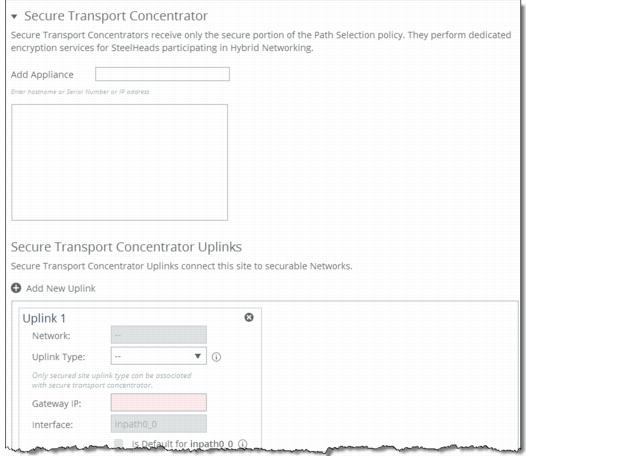
Control | Description |
Secure Transport Concentrator | Specify the secure transport concentrator. Secure transport concentrators receive only the secure portion of the path selection policy. They perform dedicated encryption services for SteelHeads participating in hybrid networking. • Add Appliance - Specify the appliance from the drop-down list to be the secure transport concentrator. In the text box, specify the hostname or serial number or IP address. The concentrators contain only appliances which will perform secure transport. |
Secure Transport Concentrator Uplinks | Specify the secure transport concentrator uplinks to connect this site to securable networks. At least one uplink, which is associated with a secure and public network, is required. Click + Add New Uplink to display the controls for configuring uplinks. You can only specify the gateway IP address for this uplink. The remaining uplink attributes are inherited from the uplinks defined for the same site. |
Control | Description |
Network | Select the network name from the drop-down list, for example, MPLS. Each uplink must have a unique interface, gateway, and probe DSCP setting. A topology does not allow duplicate uplinks. |
Uplink Type | Specify a name for similar functioning uplinks. On the SCC, uplink types can be used across multiple sites and path selection rules can be created using these names. The name must be unique at a site (but it can be same across different sites) so that the system can detect which path selection rule uses which uplinks. Because path selection rules are global on the SCC, you are restricted to 8 uplink types. Uplink types are the building blocks for path selection. For example, you can label uplink types as primary, secondary, and tertiary based on the path selection preference. The uplink type can be based on the type of interface or network resource, such as Verizon or global resource of uplink abstraction that is tied to a network. On the SteelHead, this field is called the Uplink Name, on the SCC it is the Uplink Type. |
Gateway IP | Specify the gateway IP address. |
In-Path Interface | Specify the in-path interface that relays traffic from for the uplink from the drop-down list. • Is Default for inpath0_0 - Specify to make this interface the default uplink to relay traffic through the selected interface. The SCC allows you to add many uplinks tied to the same in-path interface, or virtual uplinks. The SCC does not know which of these uplinks will be the default uplink. This option enables you to specify which in-path interface should be used as the default uplink • Enable GRE Tunneling - Specify for SteelHeads that are behind a firewall to provide IPv4 generic routing encapsulation (GRE) for direct uplinks used in path selection. Direct uplinks using GRE become direct tunneled uplinks. You must create direct tunneled uplinks to steer traffic over any uplink that traverses a stateful firewall between a server-side SteelHead and a client-side SteelHead. Without GRE, traffic attempting to switch midstream to an uplink that traverses a stateful firewall might be blocked. The firewall needs to track the TCP connection state and sequence numbers for security reasons. Because the firewall has not logged the initial connection handshake, and has partial or no packet sequence numbers, it blocks the attempt to switch to the secondary uplink and might drop these packets. To traverse the firewall, path selection can encapsulate that traffic into a GRE tunnel. For details about firewalled path selection deployments, see the SteelHead Deployment Guide. |
Bandwidth Up | (Applicable only for QoS deployments.) Specify the primary interface bandwidth up value in kilobits per second. RiOS uses the bandwidth to precompute the end-to-end bandwidth for QoS. The SCC automatically sets the bandwidth for the default site to this value. The uplink rate is the bottleneck WAN bandwidth, not the interface speed out of the WAN interface into the router or switch. For example, if your SteelHead connects to a router with a 100-Mbps link, do not specify this value—specify the actual WAN bandwidth (for example, T1 or T3). Different WAN interfaces can have different WAN bandwidths; you must enter the bandwidth link rate correctly for QoS to function properly. |
Bandwidth Down | (Applicable only for QoS deployments.) Specify the primary interface bandwidth down value in kilobits per second. RiOS uses the bandwidth to precompute the end-to-end bandwidth for QoS. The SCC automatically sets the bandwidth for the default site to this value. The uplink rate is the bottleneck WAN bandwidth, not the interface speed out of the WAN interface into the router or switch. For example, if your SteelHead connects to a router with a 100-Mbps link, do not specify this value—specify the actual WAN bandwidth (for example, T1 or T3). Different WAN interfaces can have different WAN bandwidths; you must enter the bandwidth link rate correctly for QoS to function properly. |
Probe Settings | Specify the probe settings for path selection monitoring. The SCC uses ICMP pings to monitor the uplink state dynamically. If one uplink fails, traffic is redirected to the next available uplink. When the original uplink comes back up, the traffic is redirected back to it. Specify the probe settings for the uplink: • DSCP - Select the DSCP marking for the ping packet. You must select this option if the service providers are applying QoS metrics based on DSCP marking and each provider is using a different type of metric. Path selection-based DSCP marking can also be used in conjunction with PBR on an upstream router to support path selection in cases where the SteelHead is more than a single L3 hop away from the edge router. The default marking is preserve. Preserve specifies that the DSCP level or IP ToS value found on pass-through and optimized traffic is unchanged when it passes through the SteelHead. • Timeout - Specify how much time, in seconds, elapses before the system considers the uplink to be unavailable. The default value is 2 seconds. RiOS uses ICMP pings to probe the uplinks. If the probes do not make it back within this timeout setting and the system loses the number of packets defined by the threshold value, it considers the uplink to be down and triggers an alarm. • Threshold - Specify how many time-out probes the system must receive before the uplink is considered unavailable and an alarm is triggered; the default value is 3 failed successive packets. This value also determines how many probes the system must receive to consider the uplink to be available. RiOS uses ICMP pings to monitor uplink availability. If the ping responses do not make it back within the probe timeout and the system loses the number of packets defined by this threshold, it considers the uplink to be down and triggers an alarm. • Bandwidth - Specify the maximum probing bandwidth for this uplink. You can increase the efficiency of probing by limiting the number of probes that occur per second on an uplink. The default bandwidth is 128 kbps. On the SteelHead, you can view your settings using the show path-selection debug uplinks CLI command. |