Configuring High Availability on SteelHead SD
This topic describes how to configure high availability (HA) on SteelHead SD 2.0. It includes these sections:
Previous versions of SteelHead SD supported an active-passive HA scheme. Since SteelHead SD 2.0 supports active-active HA, you can’t upgrade your SteelHead SD 1.0 HA seamlessly to SteelHead SD 2.0 HA. You must first manually unpair your master and backup appliances in SCM, upgrade to SteelConnect 2.11, and reconfigure HA in SCM.
Overview
SteelHead SD 2.0 provides active-active HA for 570-SD, 770-SD, 3070-SD appliances.
SteelConnect 2.11 provides active-active HA for SteelConnect SDI-2030 appliances located at the data center.
With active-active HA support, when a fault is detected, traffic is immediately routed to the peer appliance so that both appliances function in tandem. Traffic can be sent over any uplink regardless of the role assigned to the SteelHead SD appliance (that is, master or backup appliance). Active-active HA simplifies the configuration of uplinks for the HA pair of appliances.
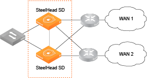
Active-active HA deployment at the branch shows an example of a symmetric deployment where the SteelHead SD HA pair are both connected to WAN 1 and WAN 2 via four uplinks.
Active-active HA deployment at the branch
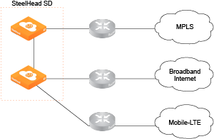
SteelHead SD also supports asymmetric HA deployments.
Asymmetric HA deployment
SteelHead SD version 2.0 includes these features:
•Support for OSPF and BGP where SteelHead SD can peer with a router.
•Support for symmetric and asymmetric connectivity.
•Support for Layer 2 (L2) and Layer 3 (L3) LAN topologies.
•Dedicated HA link for the SteelHead SD HA pair so that the peer appliances operate as a single logical unit.
•Autoconfiguration of the HA partner for bootstrapping when SCM connectivity with a peer is not accessible.
•Integration with SCM Health Check for advanced visibility and troubleshooting.
•Zscaler support for HA deployments.
Symmetric and asymmetric uplink connectivity
SteelHead SD version 2.0 provides symmetric and asymmetric uplink connectivity:
•Symmetric - In symmetric mode, each peer appliance is connected to all uplinks so that they essentially act as a single appliance. For example, you can have the 2 WAN uplinks connected to the peer appliances with four uplinks. Each uplink operates as a separate tunnel with separate IP addresses assigned to each uplink. If there is an uplink failure, the tunnel on that uplink goes down and the traffic is moved to the backup appliance. The 3070-SD supports up to 6 uplinks, where you can have 1 internet and 2 MPLS WAN uplinks for a total of 6 uplinks.
•Asymmetric - In asymmetric mode, different WANs are connected to the peer appliances. If there is an appliance failure or a LAN-side fail over, the master appliance becomes to peer appliance.
Symmetric and asymmetric HA deployment examples at the branch
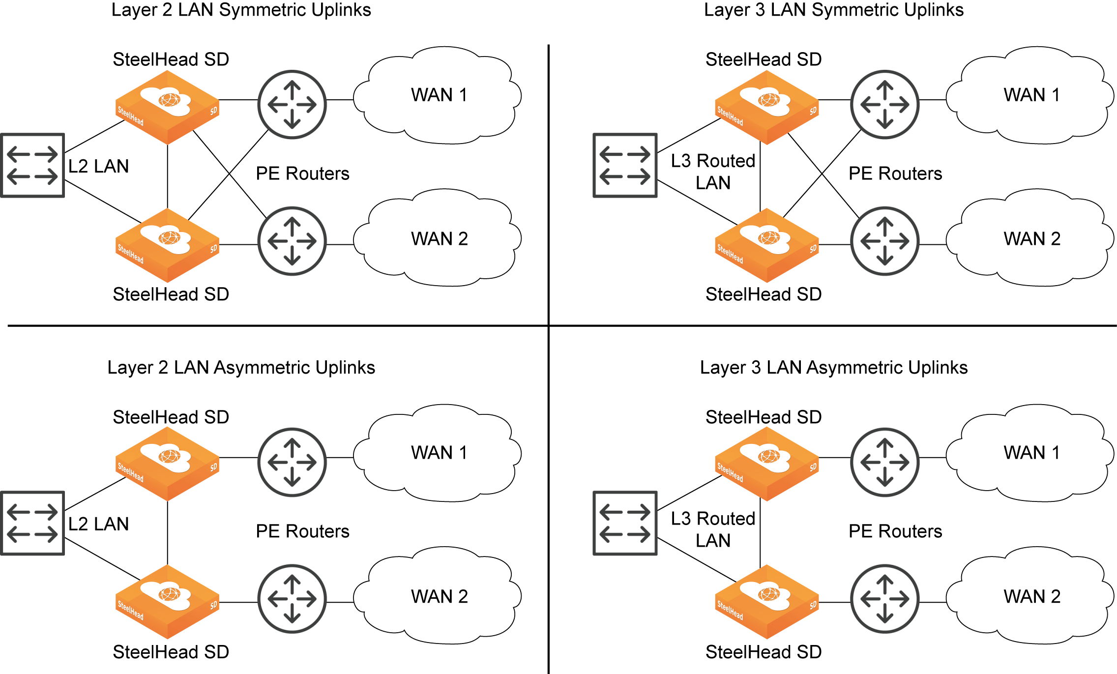
Layer 2 and Layer 3 support at the branch
With SteelHead SD 2.0, you can configure BGP and OSPF on the LAN branch.
You can configure iBGP between SteelHead SD HA peers if you want your overlay network to be advertised between the two appliances so that their routing tables are kept in synchronization. Also, you can have a combination of L2 and L3 zones so that if you have more than one LAN port configured, they can be a mix of L2 and L3. SteelHead SD uses iBGP between the peers to redistribute the overlay and connected routes.
LAN connectivity can be through either Layer 2 (L2) switch domain or Layer 3 (L3). In the case of a L3 LAN, connectivity is established through dynamic routing. SteelHead SD 2.0, supports:
•L3 LAN - You can redistribute static, connected, overlay, and WAN routes on both appliances in the HA pair. Your client traffic can go to either appliance in the HA pair. Using route convergence, the master processes the traffic and sends it on the overlay network.
•L2 LAN - With L2, you can have a switch on the LAN-side connected to SteelHead SDs that have the same LAN zone with different IP address for each appliance. The system assigns a single virtual IP address (VIP) on the zone that is owned by the master appliance. All traffic goes to the master appliance where it sends it on the overlay network. If there is a failure, the VIP moves to the backup appliance where it becomes the new master.
Multigroup VIP and Virtual Router Redundancy Protocol (VRRP) with a third-party router are not supported at this time.
Failure conditions
SteelHead SD supports appliance, uplink, LAN, and dedicated port failure conditions. The following examples illustrate some typical use cases.
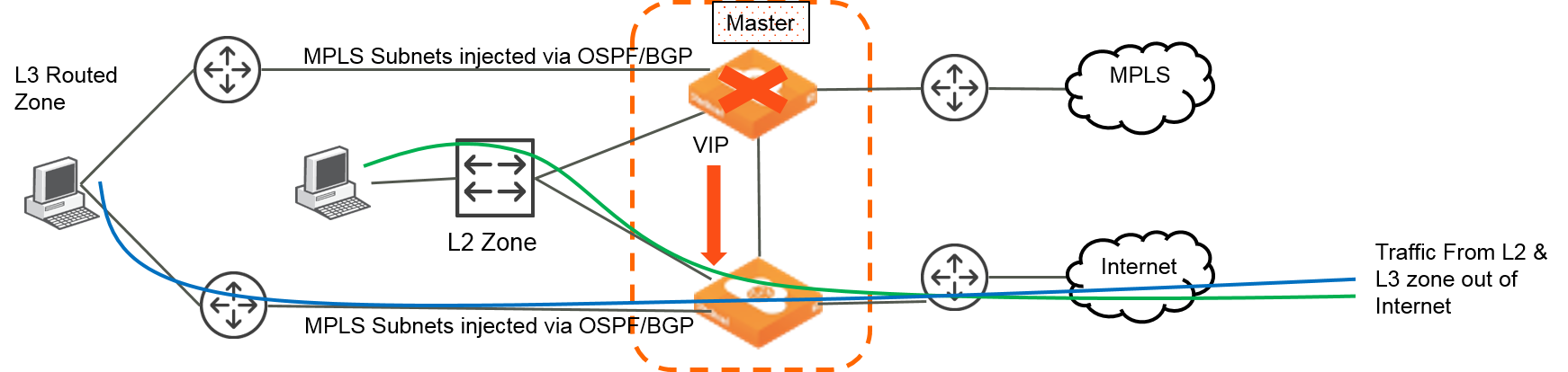
Appliance failure
For failures due to power, hardware, or VM failures, the master role is moved to the peer appliance. The VIP is moved to the new master appliance and L3 advertisements are stopped from the previous master appliance.
Appliance failure where VIP is injected into new master appliance
LAN failure
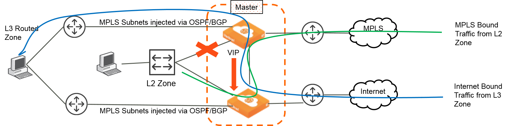
For an L2 LAN failure, the VIP moves to the backup appliance and MPLS connectivity is withdrawn. Traffic is sent through the backup appliance.
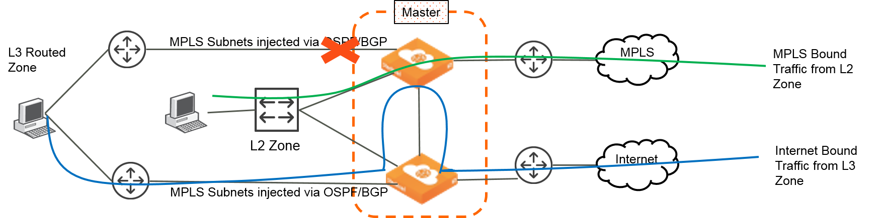
For an L3 LAN failure, routing converges to send traffic to backup appliance. Traffic is moved between appliances through the AUX port depending on which uplink the traffic needs to exit the HA pair.
L2 link failure where VIP moves to backup but no switchover of the master appliance
L3 failure where traffic continues to travel through the master appliance
AUX port failure
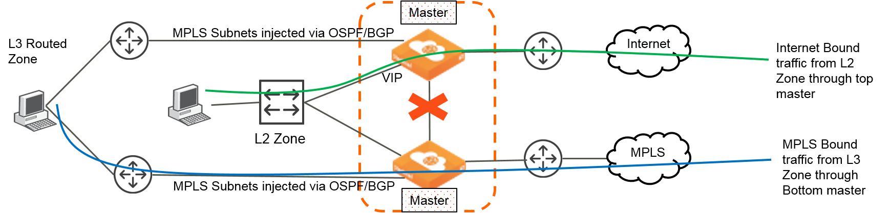
If the HA connection fails between the master and backup appliances, each appliance becomes an independent appliance. The VIP continues to be hosted by the master appliance. The MPLS networks are withdrawn on the original master appliance. The backup appliance becomes an independent master appliance and all MPLS traffic travels through it.
AUX port failure where each appliance becomes an independent master
Prerequisites
Before configuring high availability, check these requirements and recommendations. Both appliances must be:
•registered with SCM.
•running the same software version.
•cabled directly on the LAN branch using the AUX port.
•peer appliances must be located in the same zone of the branch network.
Configuring a SteelHead SD HA pair
These steps assume that you have installed, registered, and performed the initial configuration of the SteelHead SD HA pair. You should create your branch site where the HA pair will be located, along with the associated zone and uplinks. For details, see the SteelConnect Manager User Guide. This section contains these topics:
Configuring the AUX port on the HA pair
The first step is to configure the AUX port on the SteelHead SD HA pair. You will select the HA or Cluster mode for the port.
To configure the AUX port on the master and backup SteelHead SD appliances
1. On the first appliance in the pair, choose Appliances > Ports and select the site from the Site drop-down list.
2. Under Appliances, select the appliance. The ports for the appliance are displayed.
3. Select the AUX port to expand the page.
4. Under Mode, select HA from the Port mode drop-down menu.
Configuring the AUX port on the HA pair

5. Click Submit.
6. Repeat
Step 1 through
Step 5 for the peer appliance in the HA pair.
Configuring the LAN zone for the SteelHead SD HA pair
The next step is to configure the LAN zone for the SteelHead SDHA pair. If it is a Layer 2 or Layer 3 zone, you configure the correct gateway.
To configure the LAN zone
1. Choose Network Design > Zones.
2. Select the Zone for the appliance to expand the page.
3. Under IPv4 network and gateway, specify the Layer 2 or Layer 3 gateway IP address.
Configuring the LAN zone gateway
4. Click Submit.
5. Depending on your topology, repeat
Step 1 through
Step 4 for each zone in the HA branch.
Configuring the LAN zone for the SteelHead SD HA pair
After you configure the LAN zones, you must assign the LAN ports to the zones:
•If the LAN-side network is L2, the zone must to be attached to the LAN port on both appliances.
•If the LAN-side network is L3, the correct zone must be attached to the LAN ports for each of the appliances in the HA pair.
To assign the LAN port to the zone
1. To assign the appliance port to the zone, choose Appliances > Ports.
2. Select the site from the Site list.
3. Select the LAN port to expand the pane.
Configuring the LAN port
4. Under Mode, select Singlezone or Multizone. If you select Singlezone, select the zone from the drop-down list.
5. Click Submit.
6. Depending on your topology, repeat
Step 1 through
Step 5 for each appliance port that needs to be assigned to a zone.
Configuring the appliances into an HA pair
To configure the appliances into an HA pair
1. Choose Appliances and select the appliance.
2. Select the HA tab.
3. Under High availability settings, select the appliance that is in the branch.
Selecting the partner appliance in the branch
4. Click Submit.
Once the two appliances are paired, you can see them negotiate their roles in the Appliances Overview page. The master and backup roles are assigned and appear for the paired appliances.
5. If you have a Layer 2 zone in your network, click Configure Zone to configure the LAN interface IP addresses.
Configuring the LAN interfaces for Layer 2 zones
6. Select the zone for the HA pair.
7. Enter the HA IP address for the current appliance.
8. Enter the HA IP address for the partner appliance.
9. Click Submit.
Monitoring a high-availability pair
SCM displays all appliances belonging to a high-availability pair with a blue HA icon in all views. After the appliance reports its HA state to SCM, the icon indicates whether it is the master or the backup.
When an HA appliance pair lose connectivity, Appliances and Health Check display both the master and backup appliance as HA Master. For SteelHead SD appliances, SCM will not display Offline for an appliance unless the appliance actually goes offline.
Uplink tracking and LAN port tracking is not available on SteelHead SD.
SCM manages both appliances in a pair as one. For example, if you view the ports for an HA pair, they appear together.
HA pair ports

To view appliance health of an HA pair
1. Choose Health Check > Appliance Health.
Appliance health in an HA pair
2. Select the appliance to expand the page.
Viewing HA pair health details
3. Click the plus sign (+) to expand the field. For example, under Hardware, click the plus sign to the left of High Availability to view the HA IP address and status for the selected appliance.
Troubleshooting
•Make sure the roles are displayed correctly on the appliances in the Appliances > Overview page.
•All the tunnels must be up and should be using the uplinks for both the HA appliances.
•If the appliance HA role is Unknown or if the appliance pair is listed as Master/Master, make sure the AUX port (that is, the dedicated HA port) is enabled and it is configured as HA mode. If the AUX port is configured and enabled, then collect a system dump from the appliances and contact Riverbed Support at https://support.riverbed.com.
•The HA role is established with a daemon named keepalived. Search the logs for “keepalived” to debug HA issues.
•Some useful CLI commands to analyze are:
get_keepalived.sh
show_ha_info