Configuring High Availability
This topic describes how to configure high availability (HA) on SteelConnect gateways in the branches and the data center. It includes these sections:
HA overview
For all topologies, configuring high availability improves the reliability of a network by replacing a single SteelConnect gateway with two gateways in the branch or three gateways in the data center. A backup gateway maintains uninterrupted service in the event of a power, hardware, software, or WAN uplink failure. Configuring HA provides network redundancy and reliability.
SteelConnect gateway model physical appliances
This table lists the common use cases for SteelConnect gateways.
Gateway model | Use case |
SDI-130 | Small branch or retail |
SDI-330 | Medium branch |
SDI-1030 | Medium to large branch |
SDI-2030 | Regional hubs, small data centers, and large branches |
SDI-5030 | Campus or data center |
Branch high availability overview
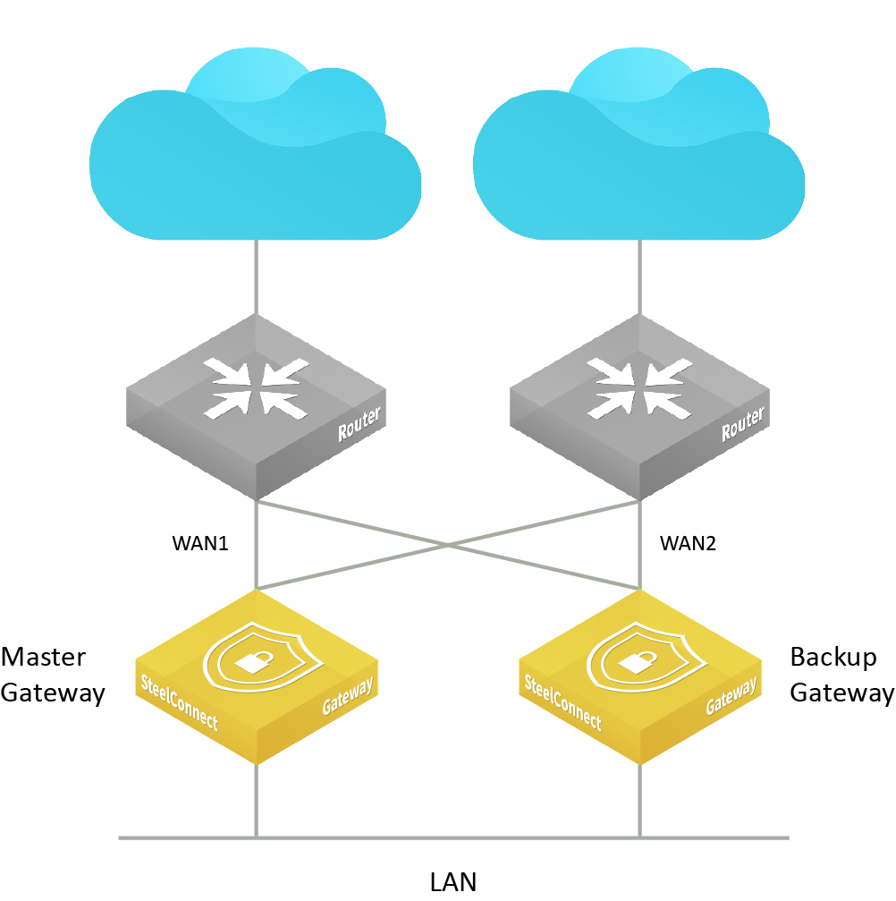
SteelConnect Manager (SCM) connects the branch gateway pair that includes the master and backup gateways over the links in the management network zone to monitor and route traffic.
The two gateways use active-passive mode. In active-passive mode, only the master gateway processes traffic while the backup gateway remains in standby mode, ready to take over if the master gateway fails.
HA active-passive deployment
How does branch high availability work?
SCM sends the master gateway configuration to both gateways. The first gateway to send Virtual Router Redundancy Protocol (VRRP) packets on the network becomes the master and SCM applies the master configuration to the gateway. No additional configuration is required on the backup gateway.
Gateways in an HA pair establish an encrypted communication channel between each other. After the communication channel is established between the master and backup gateway, the communication channel replicates all DHCP lease release and renewals between the master and backup in both directions, so that in the event of a failover, a new master gateway doesn’t assign duplicate leases.
The gateway pair also synchronizes firewall state and connection tracking information between the master and backup gateway providing stateful transition if failover occurs.
Gateway failover performance
A failover due to failure of the master gateway will trigger within 3 to 4 seconds of the master gateway going offline. After the backup gateway assumes the master role, it can pass internet traffic in approximately 9 to 10 seconds. The AutoVPN tunnels are typically reestablished after an additional 4 to 5 seconds.
Which gateway models support high availability?
SCM supports box-to-box redundancy for these gateway models:
• SDI-130 paired with another SDI-130
• SDI-330 paired with another SDI-330
• SDI-1030 paired with another SDI-1030 (requires the use of a dedicated HA port)
You can pair two gateways of the same model, two shadow appliances of the same model, or one hardware and one shadow appliance of the same model for high availability.
SteelHead SD appliances support active-active high availability. For details, see Overview of HA on SteelHead SD in the SteelHead SD User Guide.
You can use shadow and physical gateways in a high-availability pair. You can also use SDI-VGW virtual gateways.
HA features
Smart update
To ensure minimal service interruption during a firmware upgrade for an HA pair, SCM uses this smart updating process to gracefully install firmware updates:
1. SCM notifies appliances about the availability of a new firmware image.
2. The master appliance immediately starts downloading the image. The backup appliance downloads the image through a proxied connection through the master appliance.
3. After the download of the firmware image is complete on the backup gateway, SCM instructs it to install the new firmware and reboot.
At this point, the master gateway has received the new firmware file; however, it’s still handling client traffic for the HA pair and a failover has not yet occurred.
4. After SCM receives a notification from the backup gateway that it has rebooted and is running the new firmware, SCM instructs the master gateway to install the firmware and reboot.
5. The reboot triggers a failover and the backup gateway assumes the active master role.
6. After the previous master gateway comes back online, it remains in backup mode until the active gateway triggers a failover and relinquishes the active role.
WAN uplink failover
HA protects against local WAN uplink issues such as:
• an unplugged network cable between the upstream switch port on one of the gateways but not the other.
• an Ethernet port failure on the WAN port or corresponding upstream switch port.
Failover triggers after an Internet Control Message Protocol (ICMP) ping detects that one or more uplinks are down. The gateway dynamically determines an appropriate upstream IP address to ping. The ICMP uplink monitoring disregards short uplink drop-outs to avoid reporting false negatives.
WAN uplink failover performance
A WAN uplink failover triggers within 13 to 16 seconds after a down uplink is detected. After the backup gateway assumes the master role, it can pass internet traffic in approximately 9 to 10 seconds. The AutoVPN tunnels are typically reestablished after an additional 4 to 5 seconds.
For network stability, a failover can’t occur within 60 seconds of a previous failover. WAN uplink failover uses a 60-second dampening factor to limit the advertisements of up and down link transition states. For 60 seconds after a failover, the system suppresses subsequent failovers until it has enough time to verify the uplink state and analyze the gateway heuristics.
Uplinks are shared between the master and backup gateways. For example, uplink 1 and (optionally) uplink 2 are physically connected to both the master and backup gateways, so if an upstream outage occurs, both gateways are affected. To provide continued connectivity after an upstream outage, you can create a traffic rule that selects a secondary path. For details, see
To create a traffic rule.
For uplinks using IPv4 and IPv6 addresses, both IP address versions must be down before the uplink failover triggers. For example, if the IPv4 address goes down but the IPv6 address if up, the uplink doesn’t fail over.
Prerequisites
Before configuring high availability, check these requirements and recommendations.
Gateway configuration
Both gateways must be:
• cabled on the LAN side.
• cabled directly via the dedicated port in the recommended configuration.
We recommend that the gateways are cabled exactly the same for redundancy.
Switch configuration
When HA is configured, never plug in a device other than a switch directly into the gateway. For HA failover to work properly, you can configure a switch in between devices and the HA pair, so that devices can access whichever gateway is currently the master.
You can connect one or more switches directly to the HA pair; however, keep in mind that the HA pair will not forward Layer 2 traffic among the connected switches. To forward Layer 2 traffic, you must configure a core switch as a Layer 2 aggregation layer.
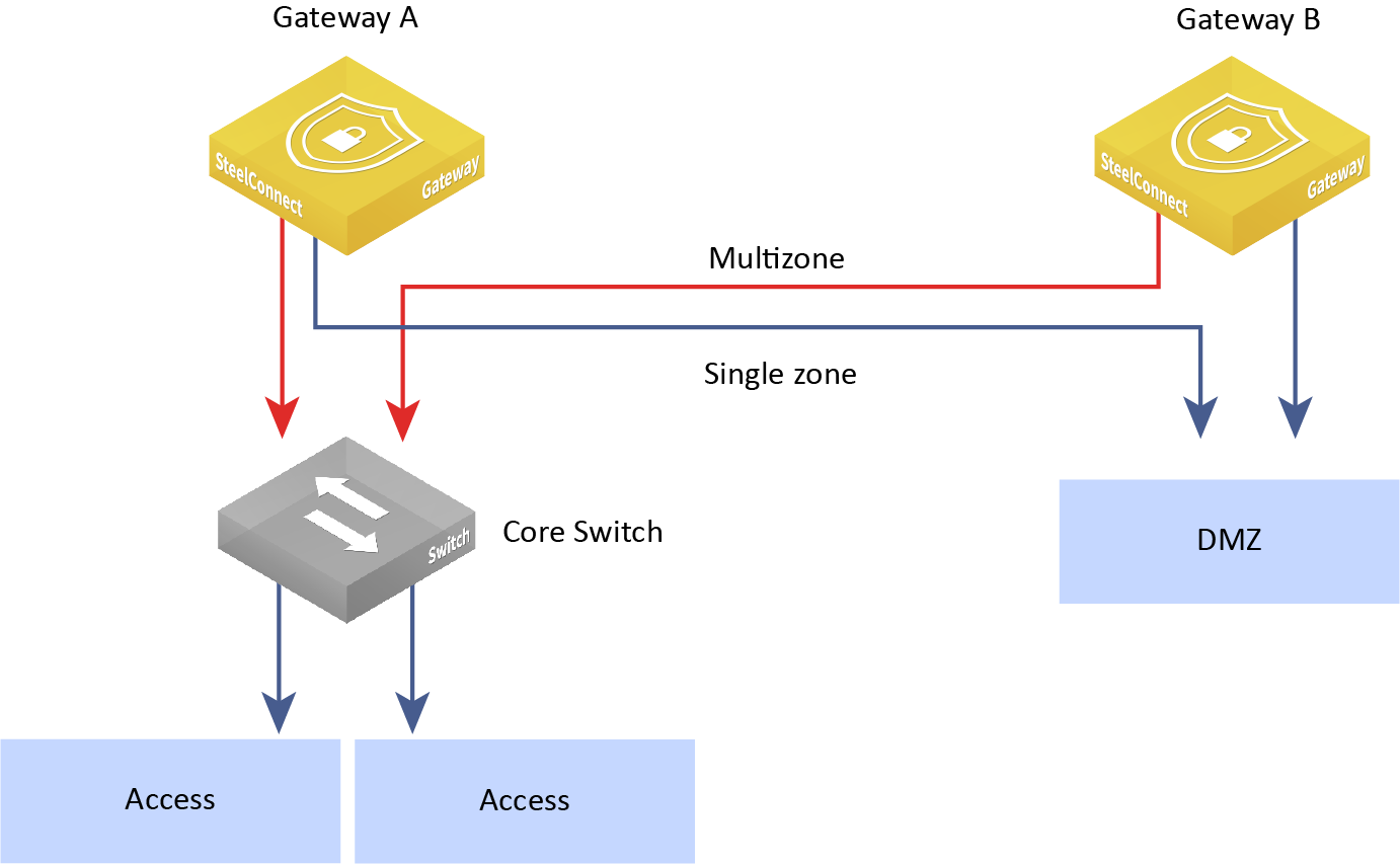
Make sure that the switches connected to the HA gateways are set to either a single-zone port or a multizone port, based on your requirements.
HA switch configuration
Individual and mirrored uplinks
Mirrored uplinks configure identical ports for the HA pair. You can assign an individual uplink to a gateway, and the upstream router assigns a port for each member of the HA pair.
Individual uplink IP addresses
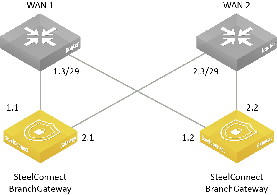
Individual uplinks don’t require a WAN-side switch, as each uplink has its own Layer 3 configuration.
When should I use nonmirrored, individual uplinks?
We recommend using mirrored uplinks. In an active-passive HA configuration, the backup gateway is passive with all uplinks and LAN ports down. The uplinks on the backup gateway aren’t actively routing traffic. However, for deployments where WAN edge equipment can provide Layer 3 ports for greater flexibility, you can associate individual uplinks with a WAN.
Figure: Mirrored and individual uplinks shows a deployment example using one mirrored and two individual uplinks.
Mirrored and individual uplinks
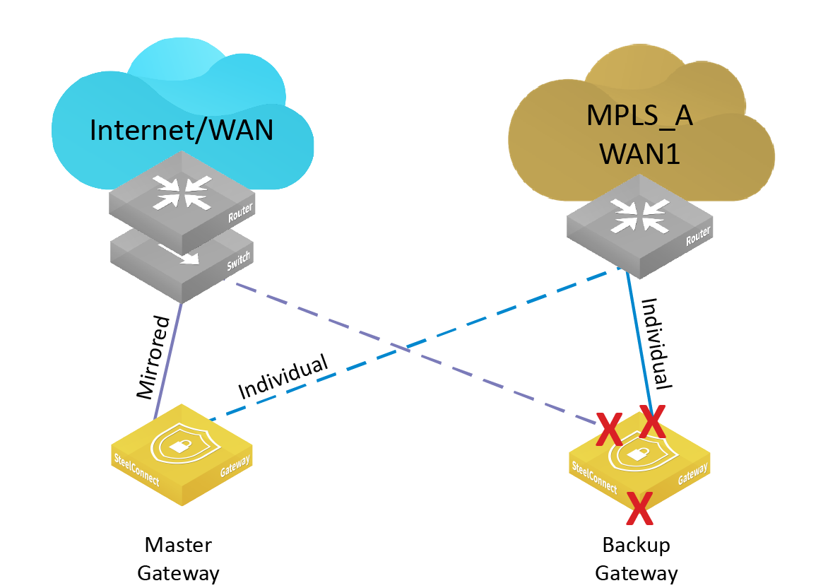
In
Figure: Mirrored and individual uplinks, the HA pair has connectivity to two WANs: an internet and an MPLS. Three uplinks are configured for the HA pair. The first is a single internet uplink in mirrored mode, as the ISP only provides a single port on their router. A WAN-side switch is necessary to achieve connectivity for both appliance’s mirrored uplink port to the single port on the internet router. The MPLS provider provides two Layer 3 ports on their PE router. For each port on the MPLS router, an individual, nonmirrored uplink is created with a Layer 3 configuration for that port and assigned to each partner in the HA pair. No switch is necessary on the MPLS WAN when using individual uplinks, because each uplink has its own unique Layer 3 configuration.
The SteelHead SD 570-SD, 770-SD, and 3070-SD appliances don’t support dedicated ports or mirrored uplinks.
Port configuration
We recommend that you configure the LAN ports such that each gateway mirrors the other; however, you can configure individual, nonmirrored LAN ports per gateway if required. Take care to ensure that the physical cabling respects the port configuration on each gateway.
To set the LAN port operation for HA
1. Choose Appliances > Ports and select a LAN port.
LAN port mode
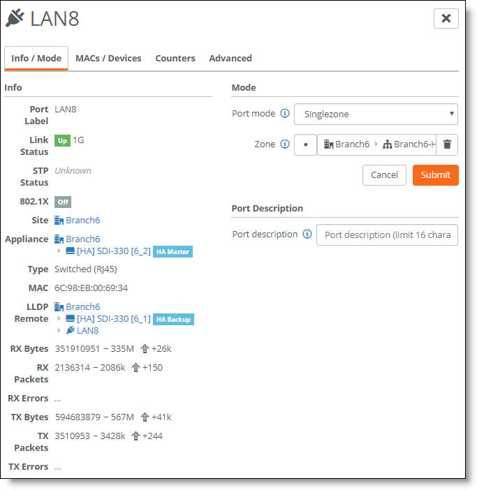
2. Under Mode, select a port mode from the drop-down list.
• Singlezone - Enables a single zone, which is the equivalent to putting a port in access mode. The zone is assigned to only one VLAN. After selecting Singlezone, select the zone for the port to carry.
• Mirrored Uplink - Configures identical ports for the HA pair. One of the nodes in the HA pair needs to have an uplink configured by selecting Uplink in the Port mode field and selecting the specific uplink that needs to be mirrored. On the HA partner, select the corresponding port by selecting Mirrored Uplink. For the mirrored uplink option to be available on the HA partner, the port number must match the partner node’s port number. Select the uplink used in the partner node. SCM configures the port identically to the corresponding port on its partner HA gateway.
When MAC cloning is enabled, mirrored uplinks inherit a virtual MAC address from one of the HA partners. SCM overrides and disables the virtual MAC address on all mirrored uplinks, and it populates the virtual MAC address on one of the HA nodes (indeterminate as to which one is selected by SCM) with the MAC address of the corresponding port on the other node.
Port modes aren’t available on ports configured as a dedicated port for HA.
3. Click Submit.
The Spanning Tree Protocol (STP) prevents network malfunction by blocking ports that can cause loops in redundant network paths. SteelConnect gateways and switches implement the Multiple Spanning Tree (MST) protocol defined in the IEEE 802.1s specification. MST is not supported on branch gateways configured for high availability.
802.1x authentication (singlezone) cannot be enabled for ports in a high-availability pair.
Tracking ports for a high-availability pair
SCM 2.9 and later extend the port failover logic for a high-availability pair with the ability to trigger failover for the HA pair when a specific LAN port in a pair fails.
We recommend two deployment options: You can use one multizone or a singlezone LAN port per gateway to the LAN switch to avoid Layer 2 loops and MAC address flapping. On the LAN-side switch we recommend disabling STP on all switch ports associated with the gateway.
For example, in a deployment with a SteelHead CX sitting behind a gateway, you can track the physical link for the LAN port for lost connectivity. After configuring tracking for one or more ports, at least one of the tracked ports in the pair must fail to trigger failover. When two ports in an HA pair are tracked, only one of the ports needs to go down to trigger failover.
We recommend using tracked ports with a common switch because the tracked ports feature prevents failover when multiple ports fail. We do not recommend using tracked uplinks with a common switch, as a failure could potentially trigger undesired HA failover. For details, see
Tracking uplinks for a high-availability pair.
To track a specific LAN port
1. Choose Appliances > Overview.
2. Select the fully configured master or backup gateway.
3. Select the HA tab.
4. Next to Tracked Ports, click the search selector and select the LAN port.
5. Click Submit.
Tracking the master port in the pair doesn’t automatically track the backup port. To track both ports, you need to repeat this procedure for the backup port as well as the master.
How do I configure an HA pair?
An HA pair configuration uses a dedicated port that allows you to select a physical port to be used for HA control traffic. The dedicated physical port is directly cabled back-to-back between the appliances.
Dedicated port mode designates a single LAN port as the HA control port. The control port is used for VRRP and routing SCM traffic for backup gateways. VRRP runs directly on the physical interface.
There is no virtual IP on this LAN port, and Layer 3 addressing is statically configured. The LAN port is isolated from customer traffic.
Configuring a dedicated port is strongly recommended for all branch HA pairs. It is required when setting up high availability between a 1030 gateway pair because it prevents loops and spanning tree issues.
We strongly recommend that you cable the gateways to each other directly using dedicated ports, and that you don’t add a switch in between the gateways. Running the HA dedicated port through switch equipment increases the risk of instability. The dedicated port is a single point of failure and any disruption on the dedicated port will cause a network outage. However, running the HA dedicated port through a switch will work, as long as the ports have Layer 2 connectivity. For this configuration, turn off the spanning tree on the switch ports that the dedicated port connects to, or at least enable PortFast on those ports to limit the risk of instability.
A dedicated port is not restricted to only the SDI-VGW and SDI-1030 gateways. You can also configure a dedicated port for the SDI-130 and SDI-330 gateways. For the SDI-1030 gateway, a dedicated port is the only option.
To configure a dedicated port
1. Choose Appliances > Overview.
2. Select the fully configured master gateway.
3. Select the HA tab.
4. Next to HA Control Link, select Dedicated Control Port from the drop-down list.
5. Select the control port from the drop-down list. This port must be cabled directly to the other gateway in the HA pair. When you dedicate a port to a gateway, it’s no longer available for use with other gateways.
Dedicated port for a gateway
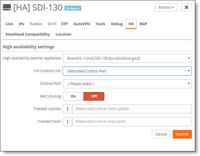
6. Click Submit.
SCM can display an inconsistent port status across SDI-130 and SDI-1030 gateways configured as the backup in a high availability pair. By design, the backup gateway doesn't actually configure its physical ports except the dedicated configured control port, any LAN port carrying management zone, and tracked ports or uplinks. In an active-passive HA configuration, the backup gateway is passive with all uplinks and LAN ports down. This behavior is not consistent with the SDI-1030 gateway, which configures its physical ports in order to speed up convergence after a HA failover. This designed behavior does not influence the performance of the HA pair. As soon as failover from the master to the backup gateway occurs and the backup gateway becomes the master, the uplinks begin actively routing traffic and SCM displays the WAN port status as up.
What impact does a failover from a backup to a master gateway have on the uplinks?
High availability supports all uplink types. When an HA pair switches a backup gateway over to a master gateway, the uplinks are impacted differently, depending on the uplink type:
• PPPoE - All connections are reestablished. The public IP address might change.
• Static IP Address - No impact.
• DHCP client - An optional virtual media access control (MAC) cloning feature is available to support addressing on the WAN interfaces. This feature clones the MAC address on the WAN uplinks for both interfaces in the HA pair. The backup gateway then uses the cloned MAC from the master gateway. This feature is useful when using a cable modem/router as an uplink and an ISP expects a consistent MAC address. The ISP can block access if it receives traffic from an unknown MAC address. This feature is disabled by default.
The cloned MAC address will also be used during failover to update the backup gateway with a new virtual MAC address. Without MAC cloning enabled, AutoVPN tunnels can take longer to reestablish after a fail over. For details on failover performance, see
Gateway failover performance.
MAC cloning only applies to mirrored uplinks. If you require specific MAC addresses on nonmirrored, individual uplinks, use the virtual MAC address feature directly. For details, see
To override a port’s default MAC address.
To enable MAC cloning
1. Choose Appliances > Overview.
2. Select the fully configured master gateway.
3. Select the HA tab.
4. Next to MAC cloning, click On.
Tracking uplinks for a high-availability pair
SCM 2.9 and later extend the uplink failover logic for a high availability pair with specific uplink failure. For example, in a deployment with several internet uplinks and one MPLS uplink, you can track the master node in an HA pair configured for the MPLS for lost connectivity.
After configuring tracking for one or more uplinks, at least one of the tracked uplinks in the pair must fail to trigger failover. When two uplinks in an HA pair are tracked, only one of the uplinks needs to go down to trigger failover.
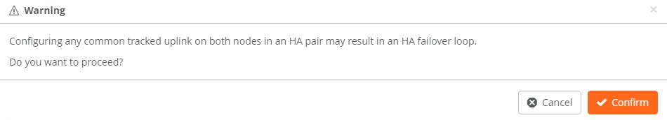
However, configuring any common tracked uplink on both nodes in an HA pair
may result in an HA failover loop.
HA failover loop warning message
When no tracked uplinks are configured, the gateway falls back to the default behavior, which triggers a failover only when all uplinks are detected to be down.
We recommend using tracked uplinks with independent WAN edge equipment where a common failure affecting both HA appliances is unlikely. Tracked ports can be used with a common device because the tracked ports feature prevents failover when multiple ports fail.
We don’t recommend using tracked uplinks with a common switch, as a failure could potentially trigger undesired HA failover. The current logic triggers the failover only if the backup uplink has fewer dead tracked ports or if one of the tracked uplinks of the current master gateway goes down.
To track a specific uplink
1. Choose Appliances > Overview.
2. Select the fully configured master gateway.
3. Select the HA tab.
4. Next to Tracked Uplinks, click the search selector and select the master uplink.
5. Click Submit.
Tracking the master uplink in the pair doesn’t automatically track the backup uplink. To track both uplinks, you need to repeat this procedure for the backup uplink as well as the master.
Monitoring a high-availability pair
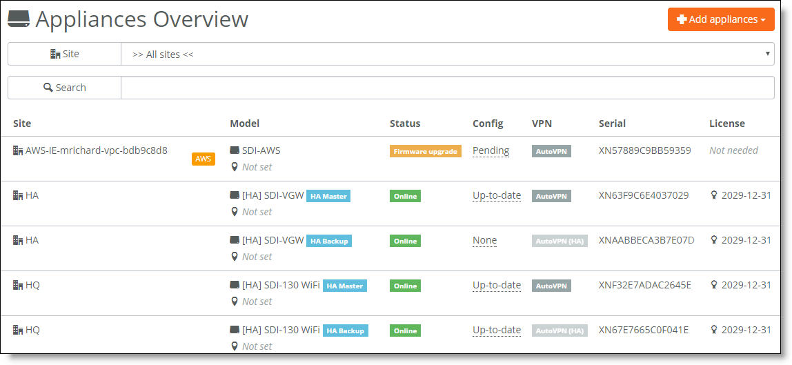
SCM displays all gateways belonging to a high availability pair with a blue HA icon in all views. After the gateway reports its HA state to SCM, the icon indicates whether it is the master or the backup.
The pair stays together in appliance lists to make it clear that the gateway is a partner that belongs in an HA pair. SCM manages both gateways in a pair as one.
Gateways in an HA pair appear together in all views
When an HA pair is separated, the gateways continue running with the same port settings, AutoVPN setting, and so on used in the HA pair. SCM unmirrors the uplinks, so one gateway will typically no longer have an uplink associated with it.
Data center high availability overview
High availability (HA) maintains uninterrupted service for a data center gateway cluster in the event of a power, hardware, software, or link failure.
SteelConnect 2.11 and later provides active-active HA for SDI-2030 appliances located at the data center and SteelHead SD appliances. For details, see Overview of HA on SteelHead SD in the SteelHead SD User Guide.
SteelConnect Manager (SCM) connects three or more 5030 gateways (nodes) to monitor and route traffic. Configuring high availability between SDI-5030 nodes provides network redundancy and reliability.
The SteelConnect data center solution uses the notation n + k to describe the engineered capacity (n) and resiliency (k) of nodes in a high-availability solution.
Because redundancy is critical, the minimum SDI-5030 high-availability cluster is deployed in an n+ k arrangement of 2 + 1.
To increase throughput, you can scale out the deployment by adding more active and spare SDI-5030 nodes.
Data center redundancy
A cluster is made up of multiple SDI-5030 nodes in a single data center. In an out-of-path deployment, the data center cluster is deployed on the server side. You can achieve resiliency by deploying at least three data center SDI-5030 nodes out-of-path at one site. In a cluster of three 5030 nodes, all three of the nodes actively handle traffic. A 2 + 1 cluster is a three appliance active quorum that tolerates one complete SDI-5030 gateway failure and remains operational.
High availability ensures no single component failure can bring down an entire cluster. Failure handling is tied to reliable semantics to detect a downed cluster node or service node. Failure recovery is initiated based on the failure notification.
A healthy cluster automatically enables data center high availability. There is no need to enable high availability after creating a cluster. For details, see
Creating clusters.
How does data center high availability work?
Each SDI-5030 node in the cluster is individually connected to SCM. SCM sends the configuration to all three SDI-5030 nodes.
Node failure
Removing or upgrading a cluster node causes connections on that node to failover and tunnels from affected data centers to reconnect.
After a node failure, a cluster rebalances the active traffic load to resume traffic flow through the nodes in under a minute.
When an active node fails, traffic flow rebalancing occurs automatically. Branch gateways handled by the failed node reconnect to the newly assigned active node. The cluster health is degraded but remains operational.
VM failure
The control virtual machine (CVM) manages appliance start up, licenses, initial configuration, and interface addressing. CVMs are interconnected through data center Layer 3 connectivity and represent an entire data center cluster as a combined manageable entity.
A CVM failure triggers a SDI-5030 node reboot. The SDI-5030 node also reboots after the CVM encounters any errors during the recovery process.
eBGP and high availability
The external Border Gateway Protocol (eBGP) is used when a tunnel endpoint (TEP) moves from one SDI-5030 node to another during a node failover. When an SDI-5030 node owning a TEP fails, the cluster transfers the TEP from the previous active node to a spare node. The spare node becomes active and now owns the TEP. It advertises the TEP into eBGP so it can attract traffic to itself.
All data center SDI-5030 nodes must use a private autonomous system number (ASN) to determine the best path between two points and also to prevent looping. During a failover, the SDI-5030 node uses the AS path prepend as follows:
• In a steady, functioning state, an SDI-5030 node prepends the ASN two times in its TEP advertisement. This creates an AS path length of three. Because it’s the only path for the TEP, it becomes the best route.
• After a failover, an SDI-5030 node becomes the new owner of a tunnel endpoint. It prepends the ASN one time to the TEP advertisement, which results in a route with the shortest AS path. This causes its route advertisement to win over any preexisting, longer path advertisements because it has an AS length of two. This route advertisement method improves network convergence time, speeding up the failover.
Which models support data center high availability?
SCM supports box-to-box redundancy for an SDI-5030 node paired with two other SDI-5030 nodes.
Switch and port configuration