Replacing SteelHead 2U xx80 and SteelCentral 1U and 2U xx80 Components
This chapter describes how to replace components in SteelHead 2U xx80 and SteelCentral 1U and 2U xx80 appliances. It includes these sections:
1U appliances included in this chapter
This chapter describes how to replace components in these 1U appliances:
• SteelCentral AppResponse 2180
• SteelCentral Flow Gateway 2280
• SteelCentral NetProfiler 4280-DP
2U appliances included in this chapter
This chapter describes how to replace components in these 2U appliances:
• SteelHead CX5080 and CX7080
• SteelCentral AppResponse 4180 and 8180
• SteelCentral NetProfiler 4280 and 4280-EXP
Required tools
You need the following tools and equipment to replace appliance components:
• You must use approved components for the appliance to function properly. Installation of unapproved components will result in boot failure. To order components, contact Riverbed Support at https://support.riverbed.com.
• An antistatic strap. When you replace appliance components, you must wear a grounded ESD antistatic strap to protect the hardware against electrostatic discharge. Make sure that the strap makes skin contact prior to handling equipment.
• Use the Riverbed magnetic reversible screwdriver (that is, Phillips and flat head) enclosed with your shipment to remove screws in the appliance. The magnetic screwdriver ensures screws aren’t lost in the appliance.
Removing the bezel
This procedure describes how to remove and install the front bezel on 1U and 2U xx80 appliances.
To remove the bezel
1. If locked, unlock the bezel.
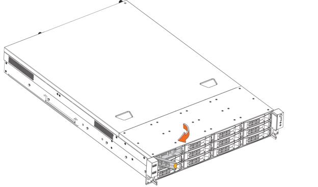
3. Pull the left side of the front bezel toward you to release the latches on the left end from the rack handle.
Figure: Removing the bezel displays a 2U appliance.
Removing the bezel
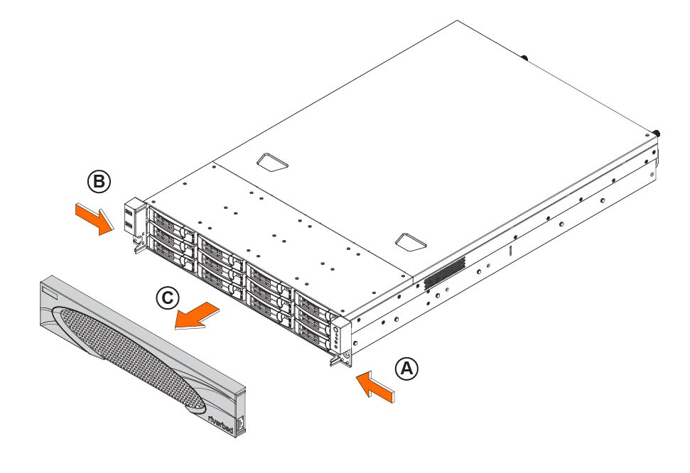
The bezel that ships with your appliance might look different from the bezel in the figure.
To install the bezel
Before installing the bezel, you must install the rack handles.
3. Lock the bezel, if needed.
Removing the chassis cover
This section describes how to remove the chassis cover on 1U and 2U xx80 appliances. It includes these sections:
The appliance must be operated with the appliance cover in place to ensure proper cooling.
Removing chassis cover on 1U appliances
This section describes how to remove and install the chassis cover on the 1U appliances.
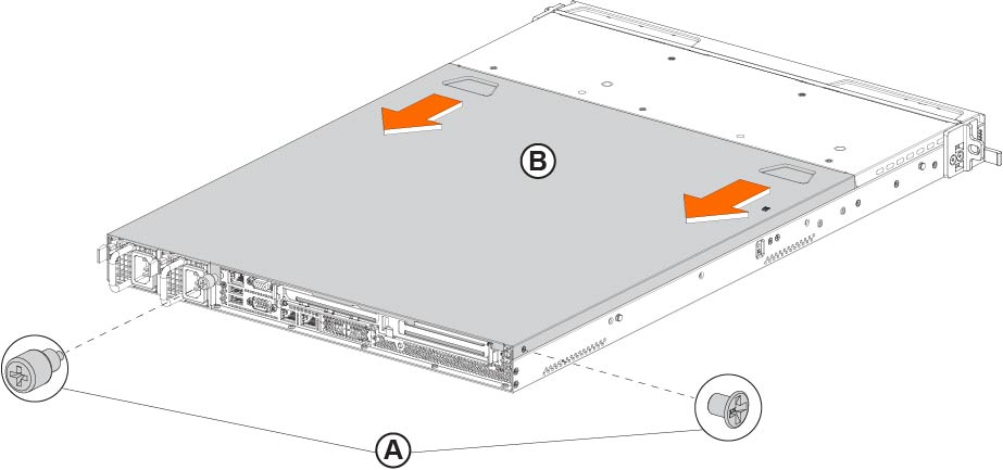
To remove the chassis cover on the 1U appliance
1. Power down the appliance and unplug all peripheral devices and the power cable.
2. Facing the back of the appliance, remove the screw on the right side and loosen the screw on the rear of the appliance. See
Figure: Removing the 1U xx80 cover, letter A.
Removing the 1U xx80 cover
Removing the chassis cover on 2U appliances
This section describes how to remove the chassis cover on the 2U xx80 appliances.
To remove the chassis cover on the 2U xx80 appliance
1. Power down the appliance and unplug all peripheral devices and the power cable.
Removing the chassis cover on the 2U xx80 appliance
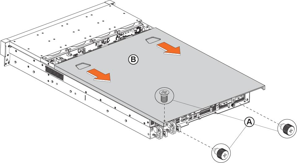
To install the chassis cover, reverse the order of these steps.
Removing the riser brackets in 1U appliances
This section describes how to remove the riser brackets in the 1U xx80 appliances.
To remove the riser brackets on the 1U appliances
2. Remove the two screws on the riser brackets.
Removing the screws on the riser brackets
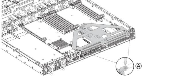
3. Lift the riser brackets out of the chassis.
Removing the riser brackets and air duct in 2U appliances
This section describes how to remove the riser brackets and air duct in the 2U xx80 appliances.
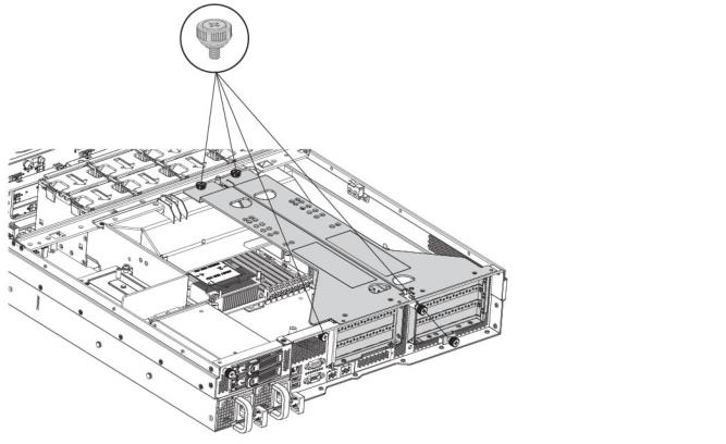
To remove the riser brackets and air duct in the 2U appliance
2. Remove the two screws on the top of the riser brackets and loosen the two screws on the back of the appliance.
Removing the screws from the riser brackets
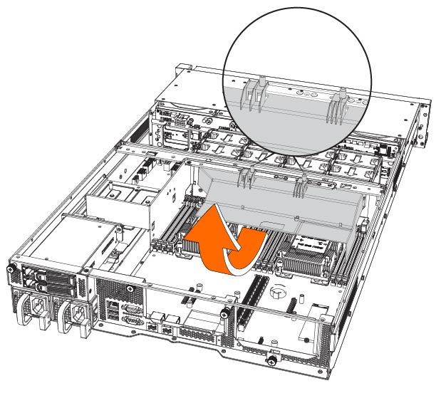
3. Lift straight up to remove the riser brackets from the chassis.
4. Release the air duct from the guide pins and then remove it from the chassis.
Removing the air duct
Replacing the disk drives
This section describes how to replace the hard disk drives (HDDs) and Solid State Drives (SSDs) in the 1U and 2U xx80 appliances. It includes these sections:
Before you begin
• When replacing a drive, replace only one drive at a time. You must use approved disk drives. To order disk drives, contact Riverbed Support at https://support.riverbed.com.
• If you need to replace an appliance, you can’t move the disks to preserve your data. Each disk is encoded with machine-level information and moving disks isn’t supported.
• When you replace disk drives, you must wear a grounded ESD antistatic strap to protect the hardware against electrostatic discharge. Make sure that the strap makes skin contact prior to handling equipment.
Always install the hard disk drive to the chassis after the chassis has been secured on the rack.
Replacing HDDs in 1U and 2U appliances
The 1U and 2U appliances are equipped with replaceable, hot-swappable disk drives. Replacement HDD 3.5-inch and SSD 2.5-inch drives are shipped in their carrier cases.
The 2U SteelCentral NetProfiler (2280, 4280-EX, and 4280-AN), SteelCentral 4180, 6180, and 8180 appliances and SteelCentral storage units are equipped with replaceable, hot-swappable 3.5-inch HDDs.
When replacing a drive, replace only one drive at a time. You must use approved disk drives. To order disk drives, contact Riverbed Support at https://support.riverbed.com.
When you replace disk drives, you must wear a grounded ESD antistatic strap to protect the hardware against electrostatic discharge. Make sure that the strap makes skin contact prior to handling equipment.
Use caution when you remove or replace components; they can become hot to the touch.
To replace the HDDs in the 1U and 2U appliance
1. Remove the bezel.
2. Identify the faulty disk drive. The disk drive LED is red for failed drives.
xx80 1U disk drive numbers

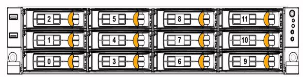
xx80 2U disk drive numbers
3. Press the orange locking-lever latch and pull the locking lever open.
Removing the disk drive
The disk drives for the 2U appliance are illustrated in
Figure: Removing the disk drive. The disk drives for the 1U appliance have the same orange locking-lever latch.
4. Slide the faulty disk drive tray out.
5. Slide in the new disk drive until it mates with the back connectors in the chassis.
6. Push to secure the locking lever until it clicks into place. The disk drive LED lights green when connected.
For SteelHead appliances, the new disk drive runs through a self-test automatically. The disk drive automatically begins proper operation with the other disk drives. You don’t need to set up or configure the new disk drive. For SteelCentral appliances, see the user guide for the product if additional steps are necessary to run a self-test.
For SteelHead appliances, it takes approximately 3 to 4 hours, depending on the system load, to rebuild a new disk drive. You can configure SteelHead appliances to send an email to the administrator user when the disk drive has finished rebuilding.
Replacing the rear SSDs in 2U appliance
The SteelCentral 2U appliance includes two hot-swappable 2.5-inch SSDs on the rear of the appliance.
To replace the rear SSD in the 2U appliance
1. Identify the faulty disk drive.
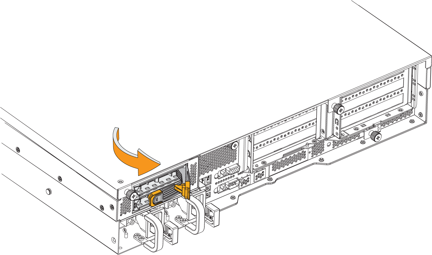
2. Press the orange locking-lever latch and pull the locking lever open.
Removing the 2.5 inch SSD on the rear of the 2U appliance
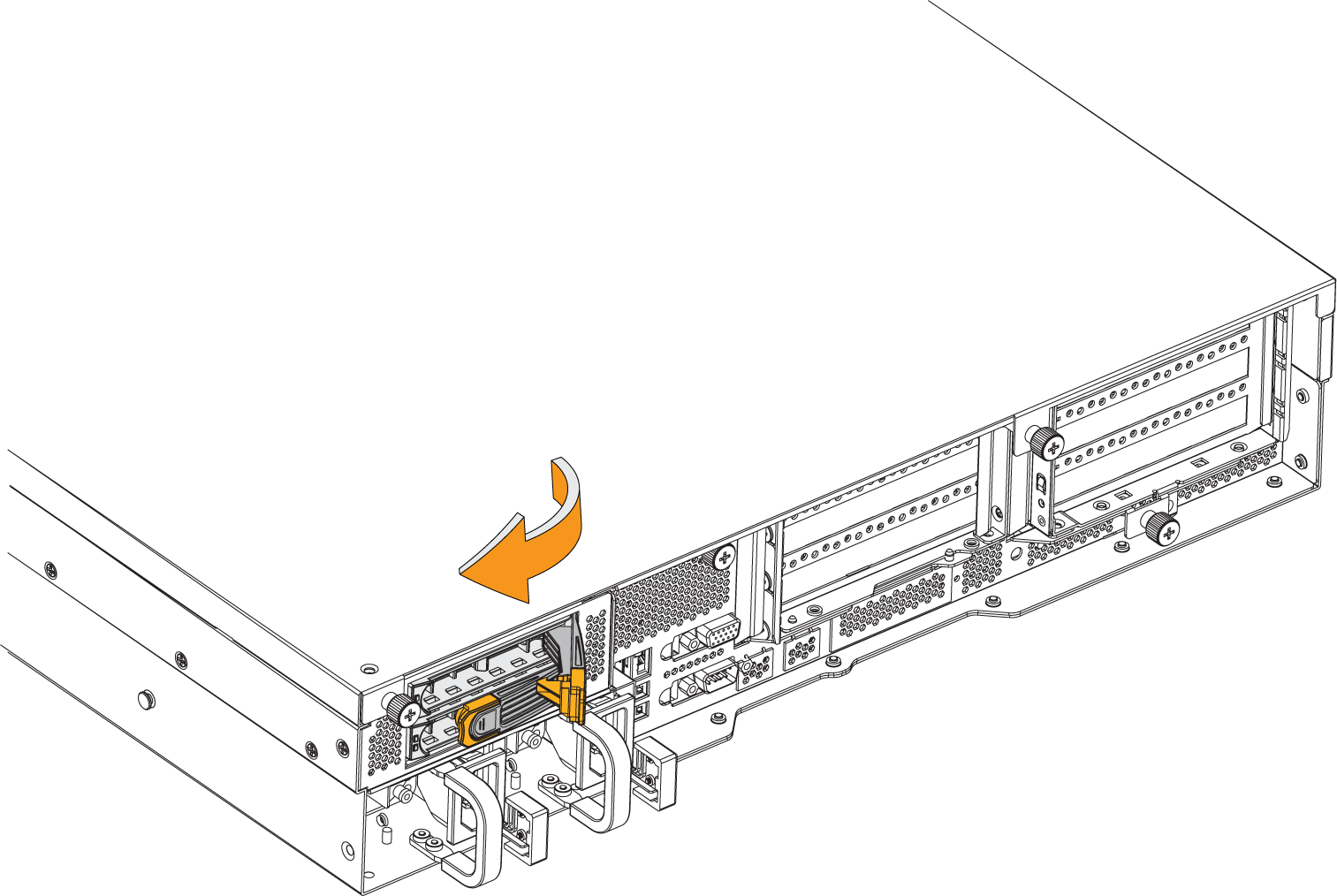
3. Insert the SSD drive into the chassis.
4. Press the locking lever to secure the drive.
Securing the drive in the chassis
Replacing power supply units in 1U and 2U appliances
This section describes how to replace a power supply (PS) in 1U and 2U appliances. These appliances are equipped with replaceable, hot-swappable PS units. The PS units are numbered:
• Facing the rear of the appliance on the 1U appliance, PS1 is on the right and power supply PS0 is on the left.
• Facing the rear of the appliance on the 2U appliance, PS0 is on the right and power supply PS1 is on the left.
Use caution when replacing the power supply units; they can become hot to the touch.
To replace power supply unit in the 1U and 2U appliance
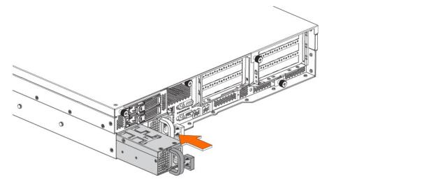
1. Locate the defective power supply unit and remove the power cord.
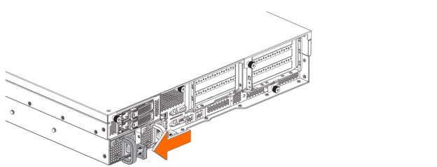
2. Press the latch and pull the power supply unit toward you.
Removing the power supply unit from 1U and 2U appliances
3. Slide the power supply unit out of the chassis.
Removing the power supply from the chassis
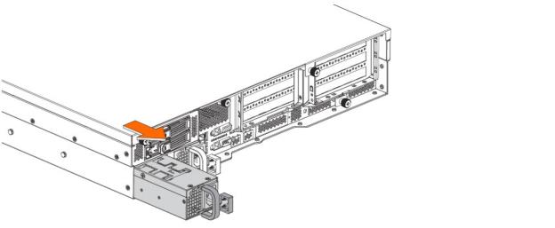
Put the defective power supply unit aside; wait until it cools down before touching it.
4. Press and hold the latch and push the power supply into the chassis using the handle.
Inserting the power supply unit for 1U and 2U appliances
5. Plug the AC power cord into the new power supply unit.
Replacing memory modules in the 1U and 2U appliances
This section describes how to remove and replace memory modules (DIMMs) in the 1U and 2U xx80 appliances.
Memory module slot locations in 1U and 2U appliances
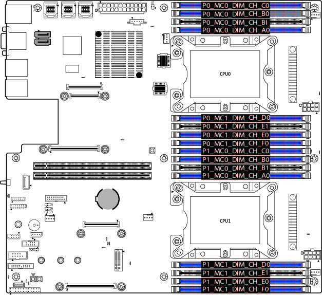
When replacing memory on the 1U and 2U xx80 appliances, place the new memory module in the slot from which the faulty memory module was removed.
When adding new memory to the 1U an 2U xx80 appliances, add the memory in the blue slots first. Once the blue slots are full, populate the black slots. Use the lowest lettered/numbered slots first.
Empty memory module slots are filled with a dummy DIMM to block and channel air. The dummy DIMM must be removed prior to adding a new memory module.
To replace a memory module in the 1U and 2U appliance
1. Power down the appliance.
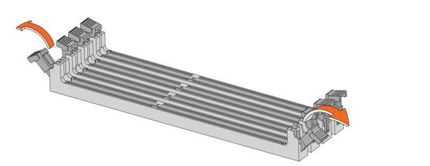
4. If you are adding a new memory module to an empty slot, make sure you remove the dummy DIMM before you add the new module to the slot.
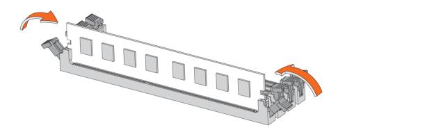
5. Press the clips outward to unlock them and gently pull the memory module out of the slot.
Releasing the locking clips
Replacing the existing memory module with a module of a different size causes the appliance to fail. You must use approved memory modules. Contact Riverbed Support at https://support.riverbed.com to obtain the correct memory modules.
6. Align the memory-module edge connector and insert it into the slot. When inserted properly, the memory slot locking levers lock automatically onto the indentations at the ends of the module.
Inserting the memory modules
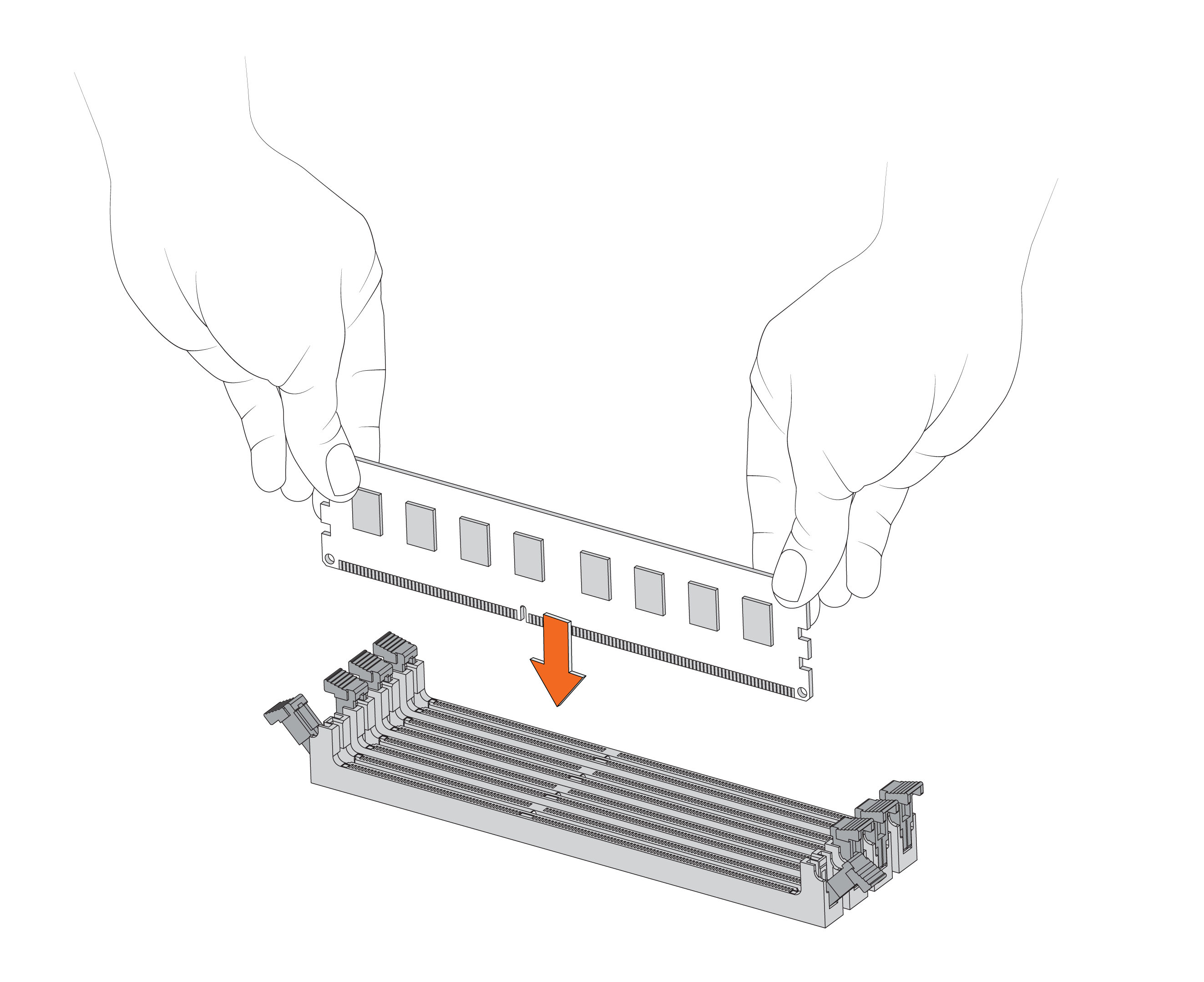
7. Press the clips inward to lock the module in place.
Ensuring the locking levers are locked.
8. Ensure that all clips are in the upright locked position.
11. Replace the power cords and peripherals.
12. Power on the appliance.
Replacing fans
This section describes how to replace fans in the 1U and 2U appliances. It includes these sections:
You must power down appliances prior to replacing fans.
Determining fan status on SteelHead
This section describes how to determine the status of individual fans in the SteelHead1U and 2U xx80 appliances.
To determine fan status on SteelHead
1. Connect to the CLI.
For details, see the Riverbed Command-Line Interface Reference Manual.
2. At the system prompt, enter the show stats fan command:
amnesiac> show stats fan
On appliances where each fan has two rotors, each rotor has a unique status entry.
The output and number of fans vary depending on your appliance.
Fan status isn’t available on NetShark.
Replacing fans in 1U appliances
This section describes how to replace fans in the 1U xx80 appliances. These appliances are equipped with six fans.
Fan layout
You must use approved fans. To order fans, contact Riverbed Support at https://support.riverbed.com.
The fans aren’t hot swappable; you must power down the appliance before replacing the fans.
To replace the fan in the 1U appliance
1. Power down the appliance.
2. Remove the chassis cover.
3. Identify the faulty fan.
4. Unplug the fan cable located on the HDD backplane.
Unplugging the fan cable
5. To remove the fan, pull straight up on each side of the fan. The fan is removed, including the attached flat metal fan bracket.
Removing the fan
6. Insert the new fan with the attached bracket into the fan slot.
Inserting the new fan
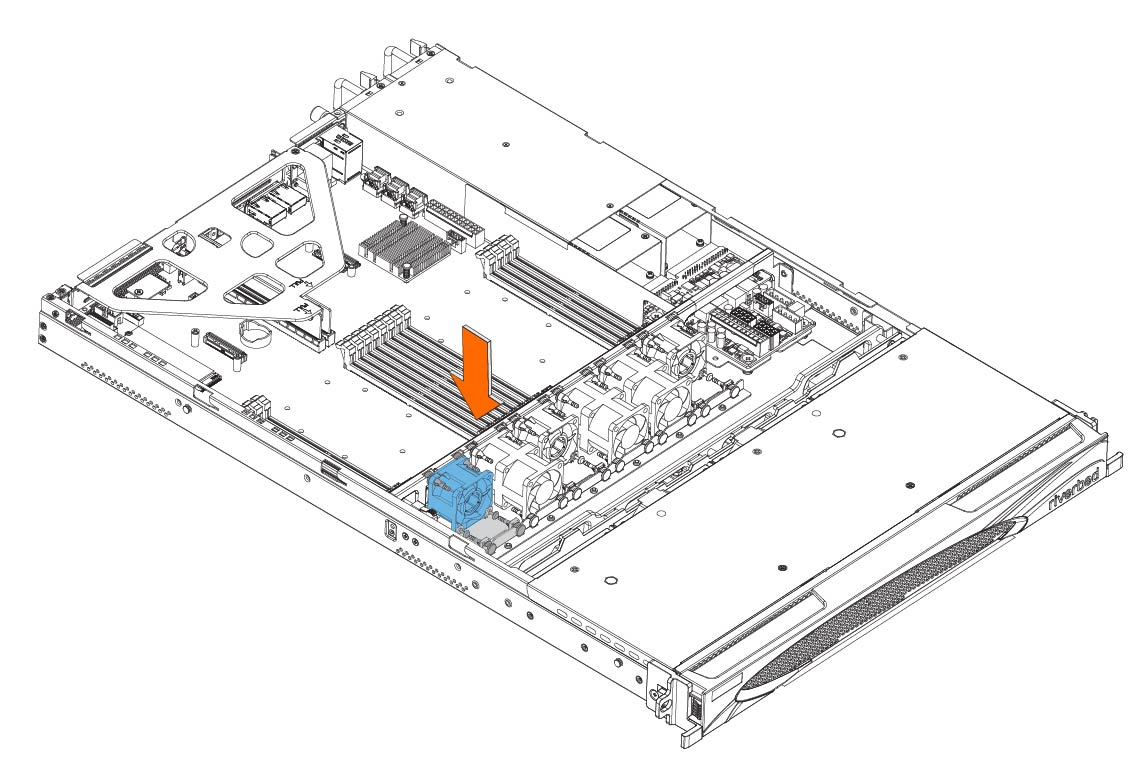
7. Plug in the fan cable to the HDD back plane.
If the RiOS IPMI alarm triggers when you open the chassis cover, enter the clear hardware error-log command in the CLI to clear the alarm. For details, see the Riverbed Command-Line Interface Reference Manual.
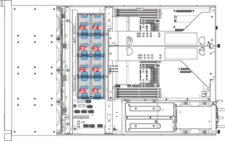
Replacing fans in 2U appliances
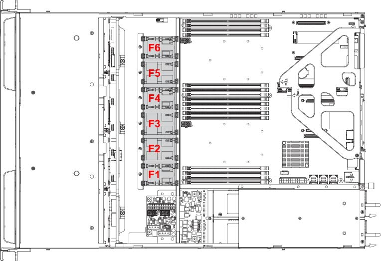
This section describes how to replace fans in 2U appliances. The SteelHead 2U xx80 and SteelConnect xx80 appliances are equipped with eight fans at the front of the chassis.
Fan layout
You must use approved fans. To order fans, contact Riverbed Support at https://support.riverbed.com.
To replace the fan in the 2U appliance
1. Power down the appliance.
3. Identify the faulty fan.
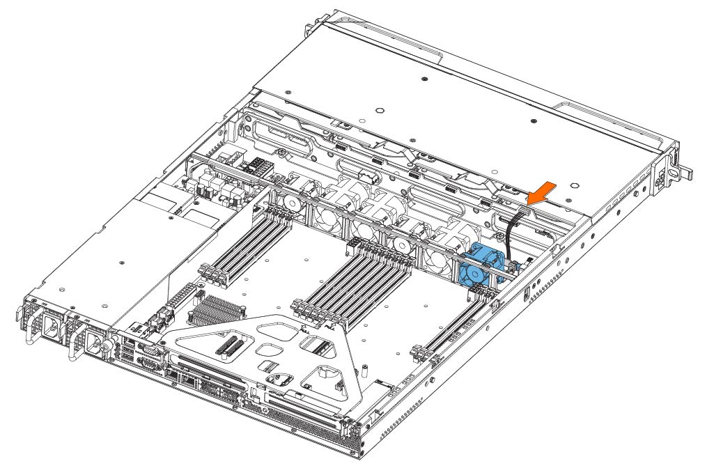
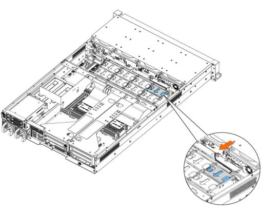
4. Disconnect the fan power cable from the backplane.
Disconnecting the fan power cable
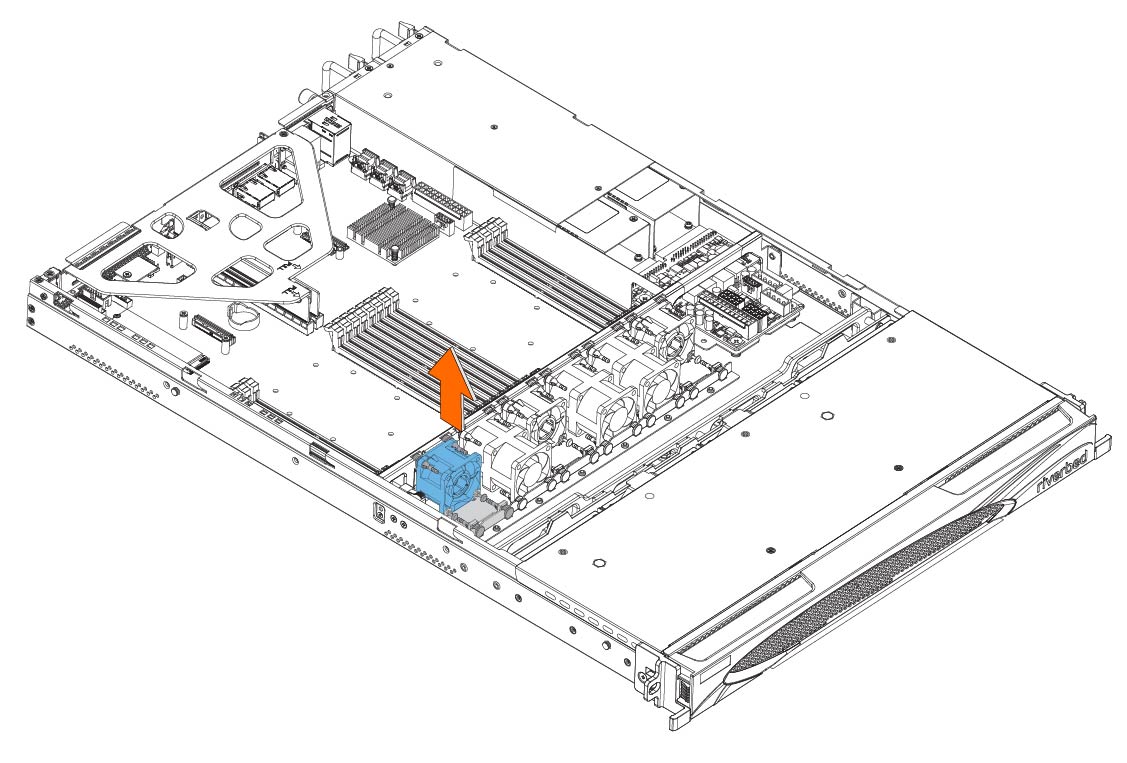
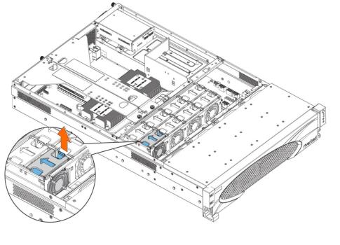
5. Press the blue button and pull the fan straight up to remove it.
Removing the faulty fan
6. Insert the new fan into the fan slot.
7. Plug in the fan power supply into the backplane.
If the IPMI alarm triggers when you open the chassis cover, enter the clear hardware error-log command in the CLI to clear the alarm. For details, see the Riverbed Command-Line Interface Reference Manual.