Replacing SteelHead CX xx55, EX xx60, and SteelFusion Core Components
This chapter describes how to replace components in SteelHead CX xx55, EX, and SteelFusion Core 2000/3000 appliances. It includes these sections:
Appliances included in this chapter
This chapter describes how to replace hardware components in the CX, EX, and SteelFusion appliances:
• Desktop appliances, including CX255, CX555, CX755, CX570, CX770, SMC9000, and SSC1000.
• 1U appliances, including CX1555 and EX1160.
For detailed information about replacing components in the EX560 or EX760 appliances, see the Series EX560 and EX760 Systems Owner’s Manual.
• 2U appliances, including CX5055, CX7055, DX8000, EX1260, EX1360, and SteelFusion Core 2000/3000 appliances.
Required tools
You need the following tools and equipment to replace components:
• You must use approved components for the appliance to function properly. Installation of unapproved components will result in boot failure. To order appliance components, contact Riverbed Support at https://support.riverbed.com.
• An antistatic strap. When you replace components, you must wear a grounded ESD antistatic strap to protect the hardware against electrostatic discharge. Make sure that the strap makes skin contact prior to handling equipment.
• Use the magnetic Phillips-head screwdriver enclosed with your shipment to remove screws in the appliance. The magnetic screwdriver ensures screws aren’t lost in the appliance.
Opening the bezel
This procedure describes how to open the front bezel on xx55, xx60, and SteelFusion Core appliances.
• To release the bezel, press the tabs on each side of the bezel and pull toward you. The bezel remains attached to the appliance on hinges.
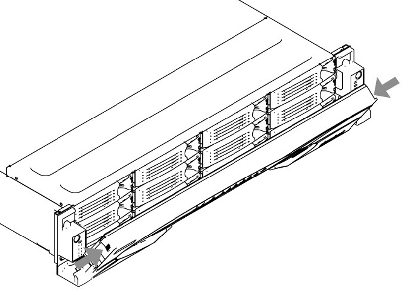
Opening the bezel on 1U and 2U xx55, xx60, and SteelFusion Core 2000 appliances
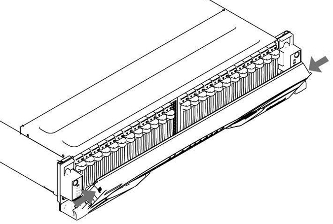
Opening the bezel on 2U xx55, xx60, and SteelFusion Core 3000 appliances
Removing the chassis cover
This section describes how to remove the chassis cover on x55, xx60, and SteelFusion Core appliances. It includes these procedures:
Removing the chassis cover on the desktop appliances
This section describes how to remove the chassis covers for the CX555 and CX755 appliances.
For instructions to remove the cover on CX255, CX570, CX770, SMC9000, and SSC1000 see
Removing disk drives in desktop appliances.
To remove the chassis cover on desktop appliances
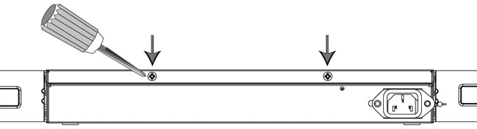
1. With the included screwdriver, remove the two locking screws on the back of the chassis cover.
Removing the locking screws
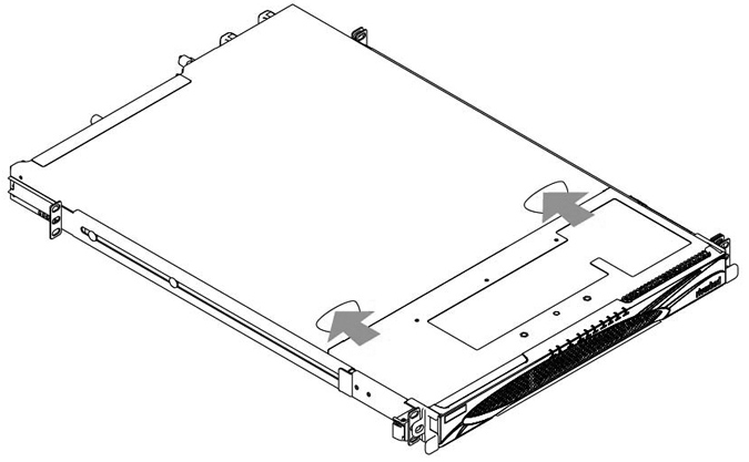
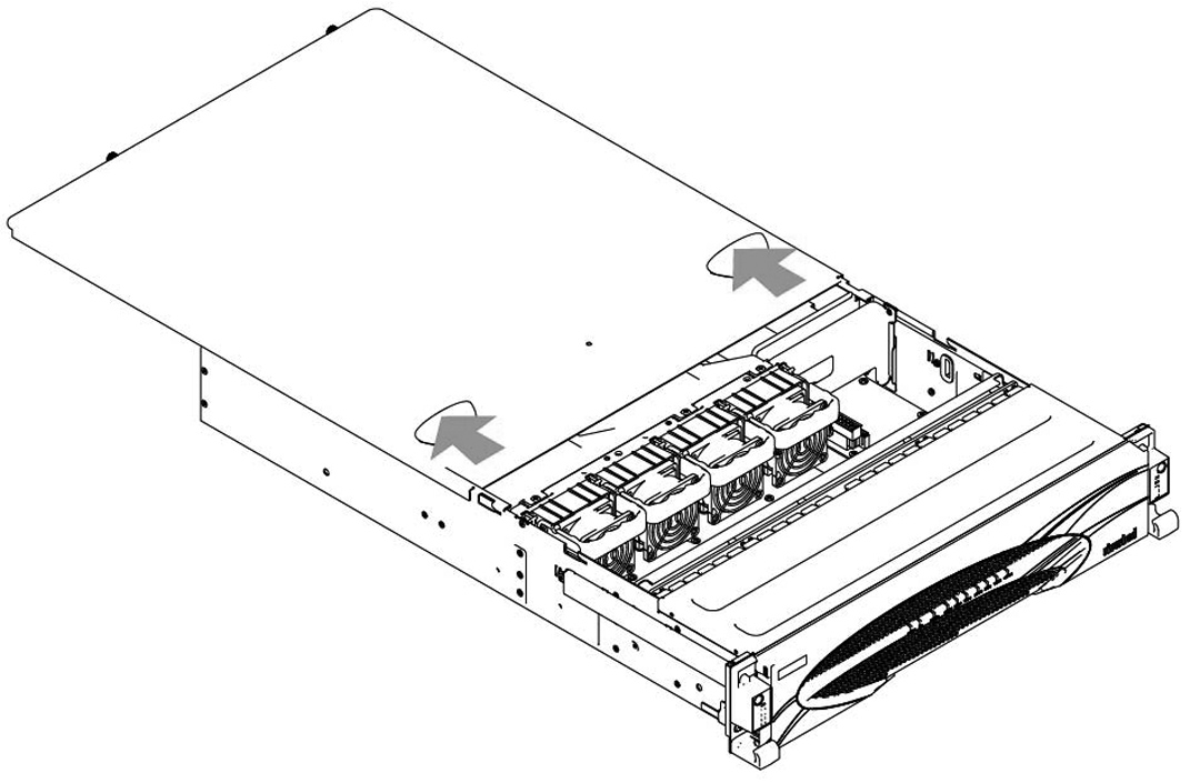
2. Position your thumbs on the top of the appliance and slide the cover back from the chassis.
Removing the chassis cover on 1U appliances
This section describes how to remove the chassis covers for the CX1555 and EX1160 appliances.
To remove the chassis cover on 1U appliances
1. Loosen the two locking screws on the back of the chassis.
Unscrewing the locking screws

2. Remove the third locking screw on the left side near the back of the top cover.
3. Position your thumbs in the indentations at the front of the appliance and slide the cover back from the chassis.
Removing the chassis cover
Removing the chassis cover on 2U appliances
This section describes how to remove the chassis covers for the CX5055, CX7055, DX8000, EX1260, EX1360, SteelFusion Core 2000, and SteelFusion Core 3000 appliances.
To remove the chassis cover on 2U appliances
1. Loosen the two locking screws on the back of the chassis.
Unscrewing the locking screws
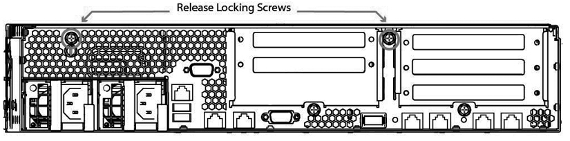
2. Remove the third locking screw on the right side of the top cover.
3. Position your thumbs in the indentations at the front of the appliance and slide the cover back from the chassis.
Removing the chassis cover
Replacing disk drives
This section describes how to remove and replace disk drives in the CX, EX, and SteelFusion Core appliances.
This section includes these procedures:
If you need to replace an appliance, you can’t move the disks to preserve your data. Each disk is encoded with machine-level information, and moving disks isn’t supported.
Removing disk drives in desktop appliances
The following desktop appliances are equipped with removable disk drives:
• CX255
• CX570
• CX770
• SMC9000
• SCC1000
When removing or replacing disk drives, be careful not to touch the adjacent power supply unit. Touching the power supply unit can cause electric shock.
Use caution when you remove or replace components; they can become hot to the touch.
To replace the disk drive
1. Power down the appliance.
2. Unplug the power cord from the AC circuit.
3. If necessary, remove the appliance from its mounting rack.
4. Remove the locking screws on the cover of the chassis. There is one locking screw located at the rear and two on each side.
Removing the locking screws

5. Slide the cover back from the appliance to remove it.
6. Locate the disk drives in the appliance and use a Phillips-head screwdriver to remove the four screws from the disk drive casing.
Removing the disk drive
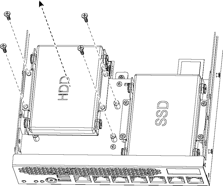
7. Detach any cables or cable units connected to the disk drive.
8. Remove the disk drive in the casing from the appliance and place the casing on an antistatic surface.
9. Remove the disk drive from the casing by removing the four screws and washers holding the disk drive casing to the chassis.
Removing the casing

Use caution when removing the screws and washers; don’t drop them into the appliance.
10. Reinsert the empty disk drive casing back in the original position and secure the casing with the original screws.
11. Replace the appliance cover using the original screws.
Replacing disk drives in 1U appliances
The 1U CX1555 and EX1160 appliances are equipped with replaceable, hot-swappable hard-disk drives (HDD) and solid-state drives (SSD).
You must use approved disk drives. To order disk drives, contact Riverbed Support at
https://support.riverbed.com.
When you replace disk drives, you must wear a grounded ESD antistatic strap to protect the hardware against electrostatic discharge. Make sure that the strap makes skin contact prior to handling equipment.
Use caution when you remove or replace components; they can become hot to the touch.
To replace the disk drive in 1U appliances
1. Open the bezel.
2. Identify the faulty disk drive.
The Alarm Status page in the Management Console identifies the faulty disk drive.
The disk drive LED is orange for failed drives.
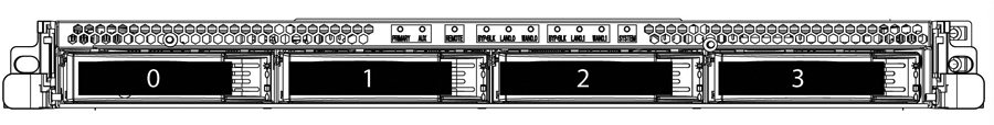
The drives are numbered in ascending order from left to right (that is, 0, 1, 2, 3). HDDs can be in any slot. SSDs can be in slots 2 and 3.
Disk drive numbers
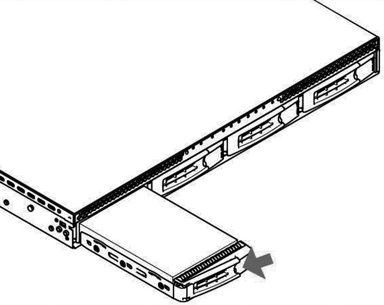
3. Press the orange release button and pull the drive handle toward you.
Releasing the disk drive
4. Slide the faulty disk drive out of the slot.
Make sure you remove the correct drive.
5. Open the new disk-drive handle by pressing the orange release button.
6. Slide in the new disk drive until it mates with the back connectors in the chassis.
The disk drive LED lights blue when connected.
7. Press in the disk-drive handle to close.
The new disk drive runs through a self-test automatically. The disk drive automatically begins proper operation with the other disk drives. You don’t need to set up or configure the new disk drive.
It takes approximately 3 to 4 hours, depending on the system load, to rebuild a new disk drive. When the disk drive has finished rebuilding, the system sends an email to the administrator user.
Replacing 2.5-inch disk drives in 2U appliances
The 2U CX5055, CX7055, DX8000, EX1360, and SteelFusion Core 3000 appliances are equipped with replaceable, hot-swappable disk drives. You must use approved disk drives. To order disk drives, contact Riverbed Support at https://support.riverbed.com.
When you replace disk drives, you must wear a grounded ESD antistatic strap to protect the hardware against electrostatic discharge. Make sure that the strap makes skin contact prior to handling equipment.
Use caution when you remove or replace components; they can become hot to the touch.
To replace a 2.5-inch disk drive in the 2U appliance
1. Open the bezel.
2. Identify the faulty disk drive.
The Alarm Status page in the Management Console identifies the faulty disk drive.
The disk drive LED is orange for failed drives.
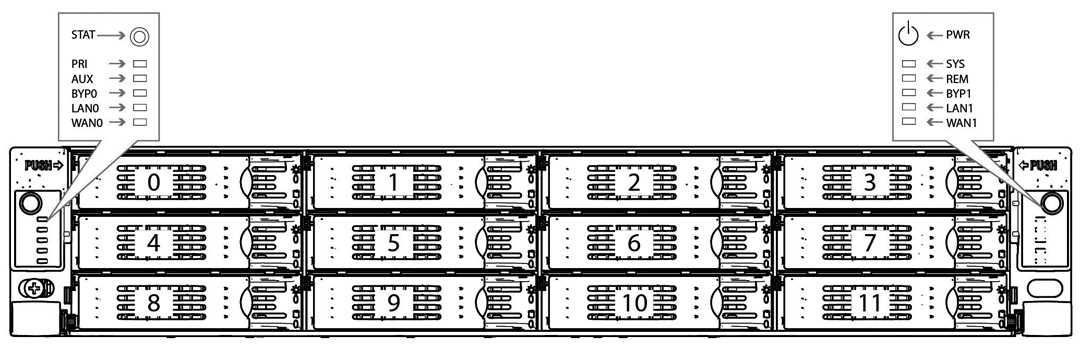
The drives are numbered in ascending order from left to right (that is, starting with 0 on the left and ending with 23 on the right).
– For the CX5055 and CX7055 appliances, disks 0 and 1 are HDDs and disks 2 to 23 are SSDs.
– For the EX1360 appliances, disks 0 to 20 are HDDs and 20 to 23 are SSDs.
– For SteelFusion Core 3000 appliances, disks 0 and 1 are HDDs. SteelFusion Core 3000 appliances don’t contain SSDs.
Disk drive number
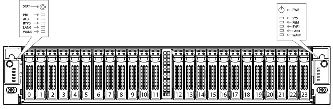
s
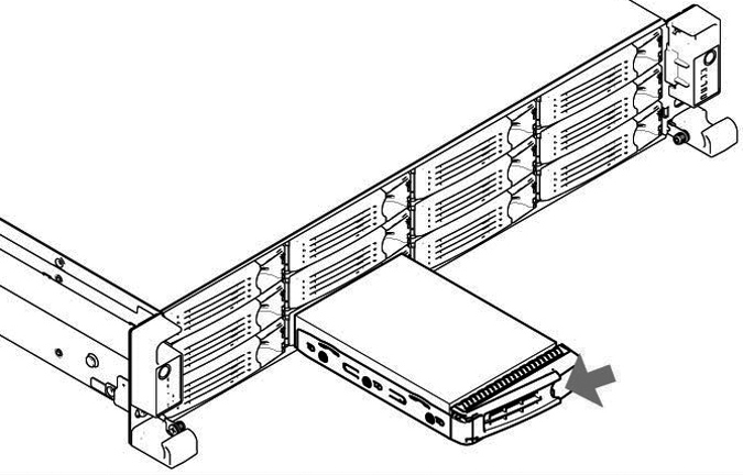
3. Press the release button and pull the drive handle toward you to release the disk drive.
Releasing the disk drive
4. Slide the faulty disk drive out of the slot.
Make sure you remove the correct drive.
5. Open the new disk-drive handle by pressing the release button.
6. Slide in the new disk drive until it mates with the back connectors in the chassis.
The disk drive LED lights blue when connected.
7. Press in the disk-drive handle to close.
The new disk drive runs through a self-test automatically. The disk drive automatically begins proper operation with the other disk drives. You don’t need to set up or configure the new disk drive.
Replacing disk drives in 2U EX1260 and SteelFusion Core 2000 appliances
The 2U EX1260 and SteelFusion Core 2000 appliances are equipped with replaceable, hot-swappable disk drives. You must use approved disk drives. To order disk drives, contact Riverbed Support at https://support.riverbed.com.
When you replace disk drives, you must wear a grounded ESD antistatic strap to protect the hardware against electrostatic discharge. Make sure that the strap makes skin contact prior to handling equipment.
Use caution when you remove or replace components; they can become hot to the touch.
To replace a disk drive in the 2U xx60 and SteelFusion Core 2000 appliances
1. Open the bezel.
2. Identify the faulty disk drive.
The Alarm Status page in the Management Console identifies the faulty disk drive.
The disk drive LED is orange for failed drives.
The drives are numbered in ascending order from the upper-left corner to the lower-right corner. HDDs can be in any slot. SSDs can be in slots 8 to 11.
Disk drive numbers
3. Connect to the CLI and enter the raid swraid fail-disk command:
amnesiac> raid swraid fail-disk <slot-number>
This command ensures the RAID system removes the disk partitions before the drive is removed from the slot. For details, see the Riverbed Command-Line Interface Reference Manual.
4. Press the orange release button and pull the drive handle toward you to release the disk drive.
Releasing the disk drive
5. Slide the faulty disk drive out of the slot.
Make sure you remove the correct drive.
6. Wait 60 seconds between removing the old drive and adding the new drive.
Waiting ensures the system detects the drive removal so it can rebuild properly after you insert the new drive. If you insert the new drive before the system detects the removal, data might be corrupted.
7. Open the new disk-drive handle by pressing the orange release button.
8. Slide in the new disk drive until it mates with the back connectors in the chassis.
The disk drive LED lights blue when connected.
9. Press in the disk-drive handle to close.
The new disk drive runs through a self-test automatically. The disk drive automatically begins proper operation with the other disk drives. You don’t need to set up or configure the new disk drive.
Replacing power supply units
This section describes how to remove and replace a power supply unit in GX, CX, EX, and SteelFusion appliances.
Replacing power supply units in 1U and 2U appliances
This section describes how to replace a power supply in 1U CX1555 and EX1160 and 2U CX5055, CX7055, DX8000, EX1260, EX1360, SteelFusion Core 2000, and SteelFusion Core 3000 appliances. These appliances are equipped with replaceable, hot-swappable power supply units.
Use gloves when replacing the power supply units; they can become hot to the touch.
To replace power supply units in 1U and 2U appliances
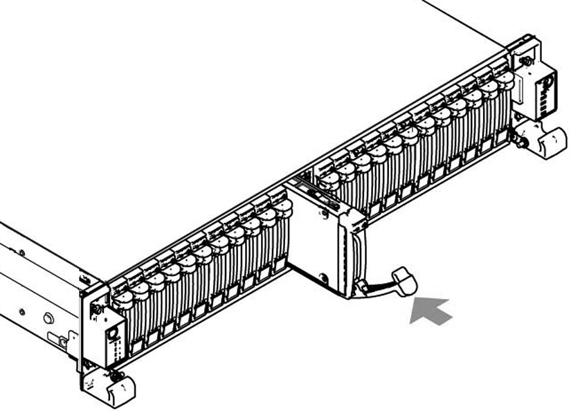
1. Locate the defective power supply unit and remove the power cord.
2. Press the release tab toward the black handle, and pull the power supply unit toward you.
Removing the PSU from 1U and 2U xx55, xx60, SteelFusion Core 2000, and SteelFusion Core 3000
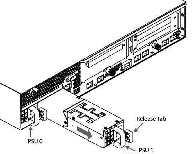
Power supply 0 (PS0) is on the left, and Power supply 1 (PS1) is on the right.
3. Pull the power supply unit out of the chassis.
Put the defective power supply unit aside; wait until it cools down before touching it.
4. Slide in the new power supply unit until it mates with the back connectors in the chassis.
When the power supply unit is pushed all the way in, the button clicks to the right.
5. Plug the AC power cord into the new power supply unit.
Replacing memory modules
This section describes how to remove and replace memory modules in the CX, EX, and SteelFusion appliances. This section includes these procedures:
Replacing memory modules in desktop appliances
This section describes how to replace memory modules in desktop CX555 and CX755 appliances.
You must use approved memory modules. Contact Riverbed Support at https://support.riverbed.com to obtain the correct memory modules.
To replace the memory modules in the desktop CX555 and CX755 appliances
1. Power down the appliance.
2. Disconnect the appliance from the electrical outlet and peripherals.
3. Remove the chassis cover.
Be careful not to touch the adjacent power supply unit. Touching the power supply unit could cause electric shock.
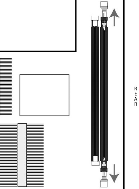
4. Press the ejector tabs on the memory slots down and outward, and gently pull the memory module out of the slot.
Accessing the memory modules
5. If you are replacing memory, remove the existing memory module and replace it with the approved memory module.
6. Align the memory-module edge connector with the slot alignment keys and insert it into the slot.
The module slot has two alignment keys that allow you to install the module in only one direction.
Inserting and securing the memory module in the DIMM slot
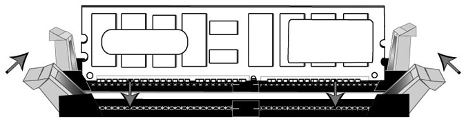
7. Press down on the memory module with your thumbs while pulling up on the ejectors with your index fingers to lock the module into the slot.
8. Ensure that all ejector tabs are in the upright locked position.
9. Replace the chassis cover.
10. Reconnect the power and power on the appliance.
Replacing memory modules in 1U appliances
This section describes how to replace memory modules in 1U CX1555 and EX1160 appliances.
Figure: Memory module slot locations in 1U CX1555 and EX1160 shows memory module slot locations in these appliances.
Memory module slot locations in 1U CX1555 and EX1160
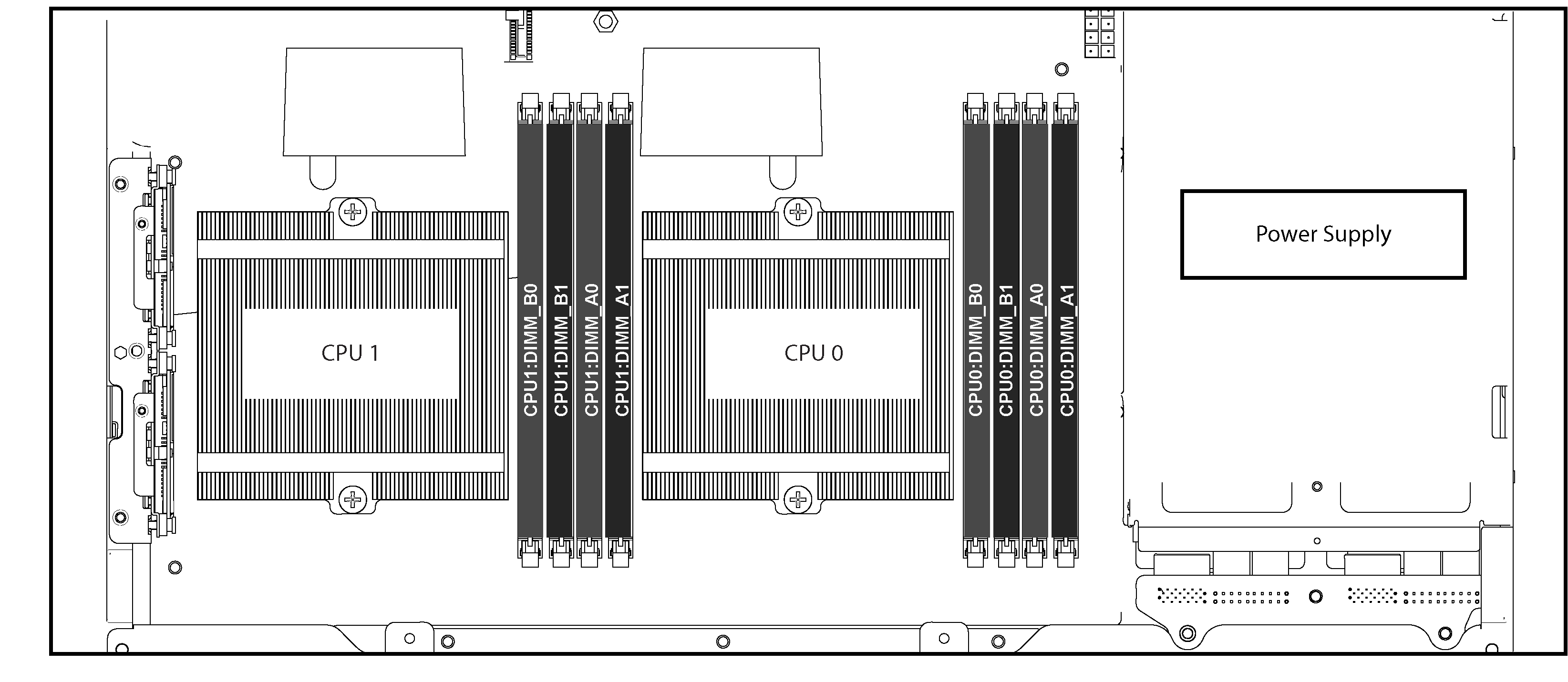
When adding new memory to the 1U CX1555 and EX1160 appliances, add the memory in the black slots first. Once the black slots are full, populate the blue slots. Make sure the memory is equally distributed on both sides.
To replace the memory modules in the 1U CX1555 and EX1160 appliances
1. Power down the appliance.
2. Remove the chassis cover.
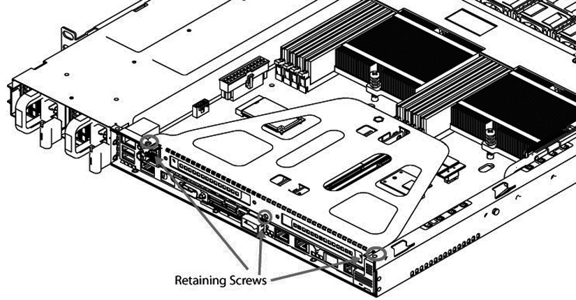
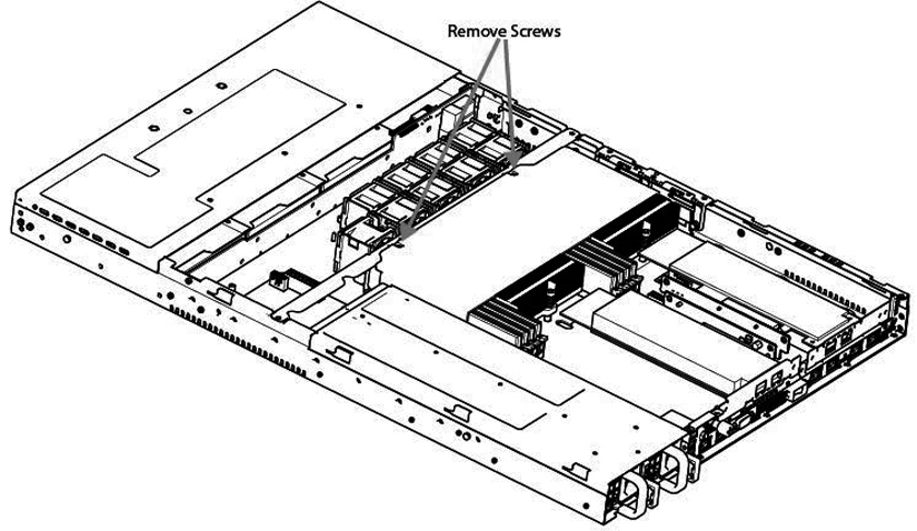
3. To access CPU 1 memory modules, you must remove the PCIe enclosure. Remove the locking screws of the PCIe enclosure on the back of the appliance.
Removing PCIe enclosure locking screws
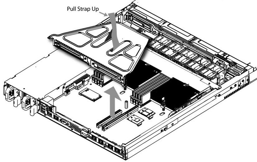
4. Lift the PCIe enclosure straight out of the appliance using the attached strap.
Removing PCIe enclosure
5. Remove the two screws securing the cooling shroud.
Removing cooling shroud screws
6. Lift the cooling shroud straight up and out of the appliance.
Lift the shroud straight up to avoid damaging any components of the appliance.
7. Press the ejector tabs on the memory slots down and outward, and gently pull the memory module out of the slot.
Accessing the memory modules
8. Remove the existing memory module and replace it with an approved memory module of the same size.
Replacing the existing memory module with a module of a different size causes the appliance to fail. You must use approved memory modules. Contact Riverbed Support at https://support.riverbed.com to obtain the correct memory modules.
9. Align the memory-module edge connector with the slot alignment keys and insert it into the slot.
The module slot has two alignment keys that allow you to install the module in only one direction.
Inserting the memory modules into the connector slot and securing
10. Press down on the memory module with your thumbs while pulling up on the ejectors with your index fingers to lock the module into the slot.
11. Ensure that all ejector tabs are in the upright locked position.
12. If necessary, replace the PCIe enclosure.
13. Replace the cooling shroud.
14. Replace the chassis cover.
15. Replace the power cords and peripherals.
16. Power on the appliance.
Replacing memory modules in 2U appliances
This section describes how to replace memory modules in the 2U CX5055, CX7055, EX1260, EX1360, SteelFusion Core 2000, and SteelFusion Core 3000 appliances.
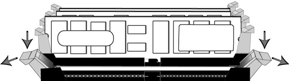
Memory module slot locations in 2U CXxx55, EXxx60, and SteelFusion Core appliances
When adding new memory to the 2U appliances, add the memory in the black slots first. Once the black slots are full, populate the blue slots. Make sure the memory is equally distributed on both sides. All memory slots for DX8000 appliances are populated.
To replace memory modules in the 2U CXxx55, EXxx60, and SteelFusion Core appliances
1. Power down the appliance.
2. Remove the chassis cover.
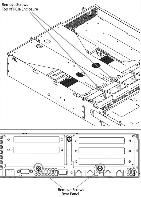
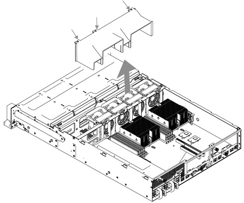
3. To release the PCIe enclosure, remove the two locking screws on the top of the enclosure and the two locking screws on the rear panel.
Removing PCIe enclosures
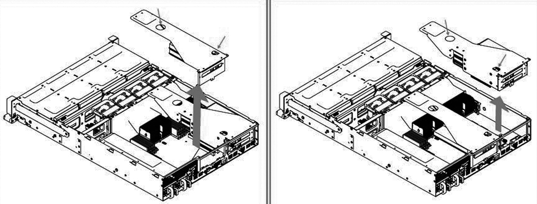
4. To remove the right and left PCIe enclosure from the chassis, place your fingers in the enclosure holes and lift straight up.
Removing the PCIe enclosures from the chassis
5. Remove the screws securing the cooling shroud to access the memory module slots.
Removing cooling shroud
Be careful not to damage any surrounding components when removing and installing the cooling shroud. Lift the shroud straight up to avoid damaging any components of the appliance.
6. Press the ejector tabs on the memory module slot down and outward and gently pull the memory module out of the slot.
Accessing the memory modules
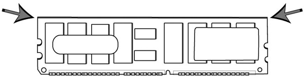
7. Hold the memory module on the outside edges to prevent damage to the module.
Proper handling of the memory module
8. Remove the existing memory module and replace it with an approved memory module of the same size. When adding memory, always replace the memory in the black slots first. Make sure the memory is equally distributed on both sides.
Replacing the existing memory module with a module of a different size causes the appliance to fail. You must use approved memory modules. Contact Riverbed Support at https://support.riverbed.com to obtain the correct memory modules.
9. Align the memory-module edge connector with the slot alignment keys and insert it into the slot.
The module slot has two alignment keys that allow you to install the module in only one direction.
Inserting the memory modules into the connector slot and securing
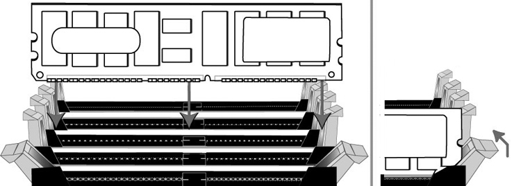
10. Press down on the memory module with your thumbs while pulling up on the ejectors with your index fingers to lock the module into the slot.
11. Ensure that all ejector tabs are in the upright locked position.
12. Repeat
Step 6 to
Step 11 of this procedure to install the remaining memory modules.
13. Replace the cooling shroud.
14. Replace the chassis cover.
15. Plug in the power cords and the peripherals.
16. Power on the appliance.
Replacing fans
This section describes how to identify fan status and replace fans in the desktop x55, the 1U and 2U xx55 and xx60, and SteelFusion Core 2000 appliances. The section includes these procedures:
The 2U CX, EX, and SteelFusion Core appliances contain hot swappable fans. You must power down desktop (CX555 and CX755) and 1U (CX1555 and EX1160) appliances prior to replacing fans.
Determining fan status
This section describes how to determine the status of individual fans in the appliance.
To determine fan status
1. Connect to the CLI.
For details, see the Riverbed Command-Line Interface Reference Manual.
2. At the system prompt, enter the show stats fan command:
amnesiac> show stats fan
FanId RPM Min RPM Status
0 4963 1080 ok
1 4963 1080 ok
2 4821 1080 ok
3 4963 1080 ok
4 4963 1080 ok
5 4821 1080 ok
The output and number of fans vary depending on your appliance.
Replacing fans in 1U appliances
This section describes how to replace fans in the 1U CX1555 and EX1160 appliances. These appliances are equipped with nine fans in a single casing. The fans aren’t hot swappable; you must power down the appliance before replacing the fans.
You must use approved fans. To order fans, contact Riverbed Support at https://support.riverbed.com.
To replace the fans in the 1U CX1555 and EX1160 appliances
1. Remove the chassis cover.
2. Unplug the fan cables from the cable jacks on the motherboard.
3. Pull the fan unit up and out of the chassis. The fans are encased in one unit.
Fan cable jacks and removing fan unit
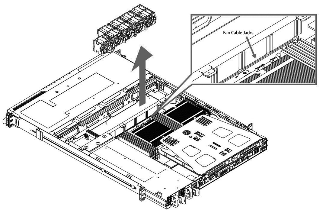
4. Seat the fan unit on the metal peg on the floor of the chassis.
5. Plug the cables of the replacement fan unit into the cable jacks.
6. Replace the chassis cover.
If the RiOS IPMI alarm triggers when you open the chassis cover, run the clear hardware error-log command in the CLI to clear the alarm. For details, see the Riverbed Command-Line Interface Reference Manual.
Replacing fans in 2U appliances
This section describes how to replace fans in the 2U CX5055, CX7055, DX8000, EX1260, EX1360, SteelFusion Core 2000, and SteelFusion Core 3000 appliances. These appliances are equipped with four dual-unit hot-swappable fans at the front of the chassis.
You must use approved fans. To order fans, contact Riverbed Support at https://support.riverbed.com.
To replace the fans in the 2U appliances
1. Remove the chassis cover.
2. Identify the faulty fan.
The appliance has four fan units, each with two fans.
2U Fan layout with fan ID numbers
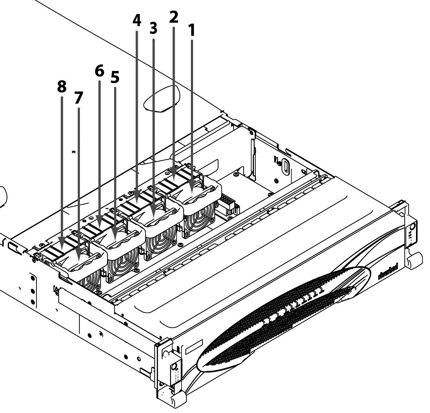
3. Pull the fan release lever upward and pull the fan up from the chassis.
Removing the fan in 2U appliances
4. Plug the replacement fan into the chassis.
5. Replace the chassis cover.
If the IPMI alarm triggers when you open the chassis cover, enter the clear hardware error-log command in the CLI to clear the alarm. For details, see the Riverbed Command-Line Interface Reference Manual.