Installing Network Interface Cards in SteelFusion Edge Appliances
This chapter provides information about how to install network interface cards (NICs) on your SteelFusion Edge appliance and includes the following sections:
Overview
The SteelFusion Edge appliances are equipped with and can accommodate add-on NICs. You can install multiport NICs to connect to multiple routers and switches.
Before you begin
This chapter assumes you have installed and configured the appliance.
During installation, make sure you follow proper ESD procedures when you handle the NIC:
• Wear properly grounded ESD straps.
• If an ESD strap is not available, touch a properly grounded metallic surface prior to handling the NIC.
• Do not touch the electronic components on the NIC.
Required tools and equipment
You need the following tools and equipment to install a card:
• Antistatic strap (required)
• A Phillips screwdriver
• Straight-through cables to connect the LAN ports to the LAN switches
• Crossover cables to connect the WAN ports to the WAN routers
Ethernet network compatibility
The SteelFusion Edge appliances support the following Ethernet networking standards:
• Ethernet Logical Link Control (LLC) (IEEE 802.2 - 1998)
• Fast Ethernet 100 Base-TX (IEEE 802.3 - 2008)
• Gigabit Ethernet over Copper 1000 Base-T and Fiber 1000 Base-SX (LC connector) and Fiber 1000 Base LX (IEEE 802.3 - 2008)
• 10-Gigabit Ethernet over Fiber, 10 GBase-LR Single Mode, and 10 GBase-SR Multimode (IEEE 802.3 - 2008)
The ports support the following connection types and speeds:
• Primary - 10/100/1000 Base-T, auto-negotiating
• Auxiliary - 10/100/1000 Base-T, auto-negotiating
• LAN - 10/100/1000 Base-TX or 1000 Base-SX or 1000 Base-LX or 10GBase-LR or 10GBase-SR, depending on configuration
• WAN - 10/100/1000 Base-TX or 1000 Base-SX or 1000 Base-LX or 10GBase-LR or 10GBase-SR, depending on configuration
• Management - 10/100/1000 Base-T, auto-negotiating
The appliance supports VLAN tagging (IEEE 802.3 - 2008). It does not support the ISL protocol.
All copper interfaces are autosensing for speed and duplex (IEEE 802.3 - 2008).
The appliance auto-negotiates speed and duplex mode for all data rates and supports full-duplex mode and flow control (IEEE 802.3 - 2008).
A SteelFusion Edge appliance with a Gigabit Ethernet card supports jumbo frames on in-path and primary ports.
Supported NICs for SteelFusion Edge appliances
The SteelFusion Edge appliances support two independent nodes with their own management and monitoring. The RiOS node and hypervisor node each operate independently of each other and support their own NICs. NICs are supported for their intended use. Nonbypass cards are treated as data NICs, and bypass cards are treated as in-path NICs. You cannot change a data NIC to an in-path NIC, or vice versa, from the GUI or the CLI.
The SteelFusion Edge 2100 and SteelFusion Edge 2200 offer two slots for RiOS functionality. Slot 1 is populated by default with the four-port 1-GbE copper bypass card. Slot 2 can support an additional NIC. See the table below for the options available on the 1U SteelFusion Edge appliance.
The SteelFusion Edge 3100, SteelFusion Edge 3200, and SteelFusion Edge 5100 offer six slots where slots 1 to 4 support RiOS management and functionality and slots 5 and 6 support hypervisor functionality. Slot 1 is populated by default with the four-port 1-GbE copper bypass card with LSI controller. See the table below for the options available on the 2U SteelFusion Edge appliance.
Note: Card naming will occur accordingly when a NIC is installed. If you replace a nonbypass card with a bypass card in the same slot, the card naming will change and you may see unexpected results.
The following table lists the NICs supported on the SteelFusion Edge appliances for RiOS and hypervisor functionality.
Do not install other cards on the SteelFusion Edge appliances.
NIC description | Orderable part number | 1U slots supported | 2U slots supported | Node |
Four-port 1-GbE copper base-T | NIC-2-001G-4TX-BP | Slot 1 only | Not supported | RiOS |
Four-port 1-GbE copper base-T | NIC-1-001G-4TX-BP | Slot 2 only | Slots 2, 3, or 4 | RiOS |
Four-port 1-GbE fiber SX | NIC-1-001G-4SX-BP | Slot 2 only | Slots 2, 3, or 4 | RiOS |
Two-port 1-GbE fiber SX | NIC-1-001G-2SX-BP | Slot 2 only | Slots 2, 3, or 4 | RiOS |
Two-port 1-GbE fiber LX | NIC-1-001G-2LX-BP | Slot 2 only | Slots 2, 3, or 4 | RiOS |
Four-port 1-GbE fiber LX | NIC-1-001G-4LX-BP | Slot 2 only | Slots 2, 3, or 4 | RiOS |
Two-port 10-GbE fiber SR | NIC-1-010G-2SR-BP | Slot 2 only | Slots 2, 3, or 4 | RiOS |
Two-port 10-GbE fiber LR | NIC-1-010G-2LR-BP | Slot 2 only | Slots 2, 3, or 4 | RiOS |
Combo Card - four-port 1-GbE copper base-T + LSI controller | NIC-2-001G-4TX-EXP-BP | Not supported | Slot 1, 3, or 4 | RiOS |
Four-port 1-GbE copper base-T | NIC-1-001G-4TX | Slot 2 only | Slots 2, 3, or 4 | RiOS |
Slots 5 or 6 | Hypervisor |
Two-port 10-GbE copper base-T | NIC-1-010G-2TX | Slot 2 only | Slots 2, 3, or 4 | RiOS |
Slots 5 or 6 | Hypervisor |
Four-port 10-GbE copper base-T | NIC-1-010G-4TX | Slot 2 only | Slot 2 | RiOS |
Slots 5 or 6 | Hypervisor |
Two-port 10-GbE SFP+
(DAC, SR, LR) | NIC-1-010G-2SFPP | Slot 2 only | Slots 2, 3, or 4 | RiOS |
Slots 5 or 6 | Hypervisor |
Four-port 10-GbE SFP+
(DAC, SR, LR) | NIC-1-010G-4SFPP | Slot 2 only | Slots 2, 3, or 4 | RiOS |
Slots 5 or 6 | Hypervisor |
Four-port 1-GbE SFP
(Copper, SX, LX) | NIC-1-001G-4SFP | Slot 2 only | Slots 2, 3, or 4 | RiOS |
Slots 5 or 6 | Hypervisor |
Two-port 40-GbE multimode (fiber) | NIC-1-040G-2SR4-BP | Not supported | Slot 3 | RiOS |
Not supported | Hypervisor |
Two-port 40-GbE multimode (fiber) | NIC-1-040G-2LR4-BP | Not supported | Slot 3 | RiOS |
Not supported | Hypervisor |
Four-port 10-GbE fiber SR | NIC-1-010G-4SR-BP | Not supported | Slot 3 | RiOS |
Not supported | Hypervisor |
Four-port 10-GbE fiber LR | NIC-1-010G-4LR-BP | Not supported | Slot 3 | RiOS |
Not supported | Hypervisor |
Four-port 10-GbE multimode (Copper TX) | NIC-1-010G-4TX-BP | Not supported | Slot 3 | RiOS |
Not supported | Hypervisor |
Four-port 10-GbE multimode (Copper ER) | NIC-1-010G-4ER-BP | Not supported | Slot 3 | RiOS |
Not supported | Hypervisor |
Four-port 10-GbE multimode (Copper DAC) | NIC-1-010G-4DAC-BP | Not supported | Slot 3 | RiOS |
Not supported | Hypervisor |
SFP | Manufacturing part number | Orderable part number |
SFP+ 10-GbE DAC | 410-00142-01 | TRC-1-SFPP-DAC |
SFP+ 10-GbE SR | 410-00143-01 | TRC-1-SFPP-SR |
SFP+ 10-GbE LR | 410-00144-01 | TRC-1-SFPP-LR |
SFP 1-GbE LX | 410-00140-01 | TRC-1-SFP-LX |
SFP 1-GbE SX | 410-00139-01 | TRC-1-SFP-SX |
SFP 1-GbE copper | 410-00138-01 | TRC-1-SFP-TX |
Note: The dual 10-GbE SFP+ card requires the SteelFusion Edge 4.2 software version or later. All other NICs require SteelFusion Edge 4.0 or later.
Installing NICs in 1U SteelFusion Edge appliances
This section describes how to install NICs in 1U SteelFusion Edge appliances.
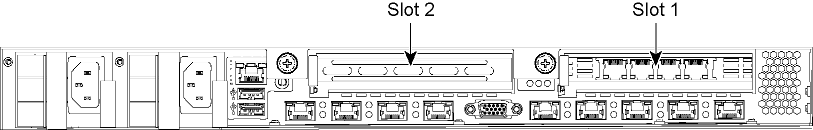
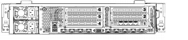
Figure: NIC slot locations for 1U SteelFusion Edge appliances identifies the Peripheral Component Interconnect Express (PCIe) slot locations.
Figure: NIC slot locations for 1U SteelFusion Edge appliances
To install a NIC in the 1U appliances
1. Power down the appliance.
2. Remove the power-supply cord.
3. Remove the cables connected to the appliance.
4. Remove the appliance from the mounting rack, if necessary.
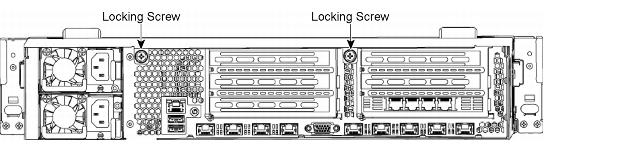
Figure: Locking screws
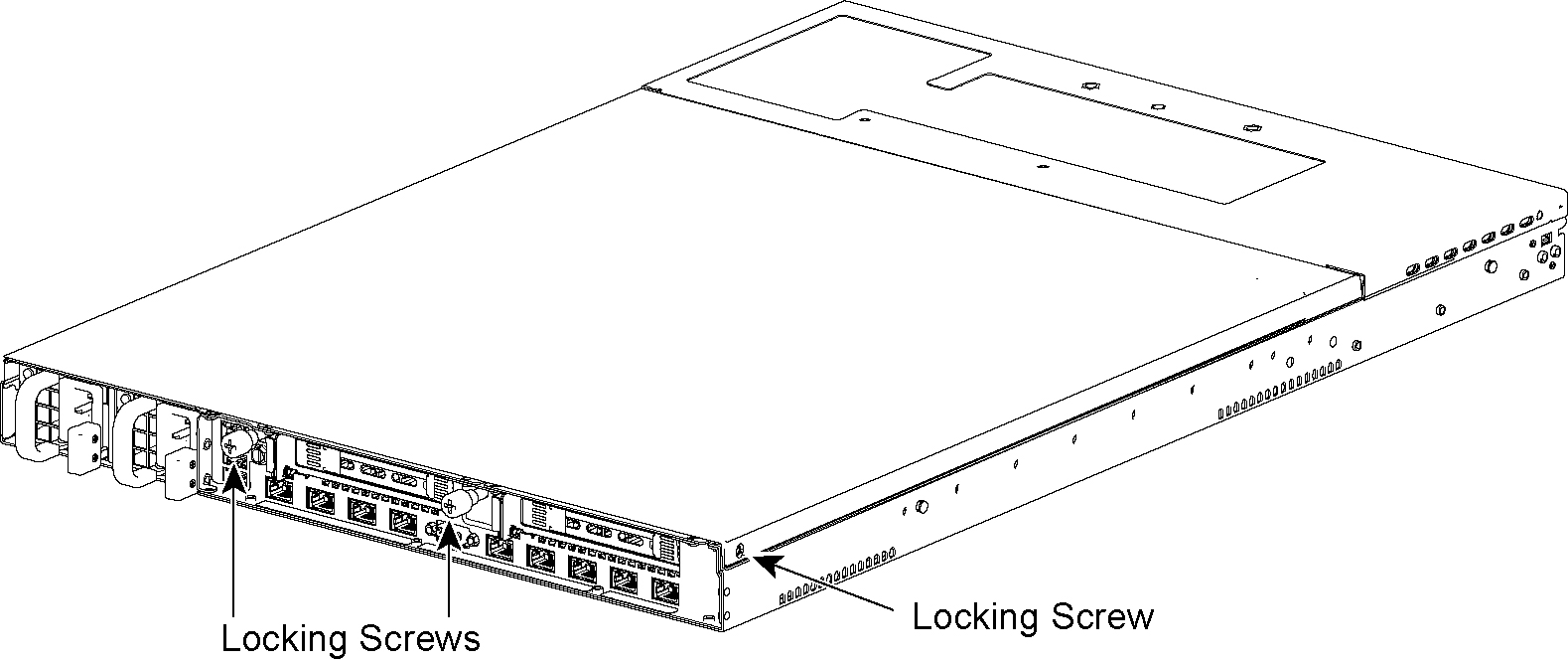
6. Remove a third locking screw on the left side near the back of the top cover.
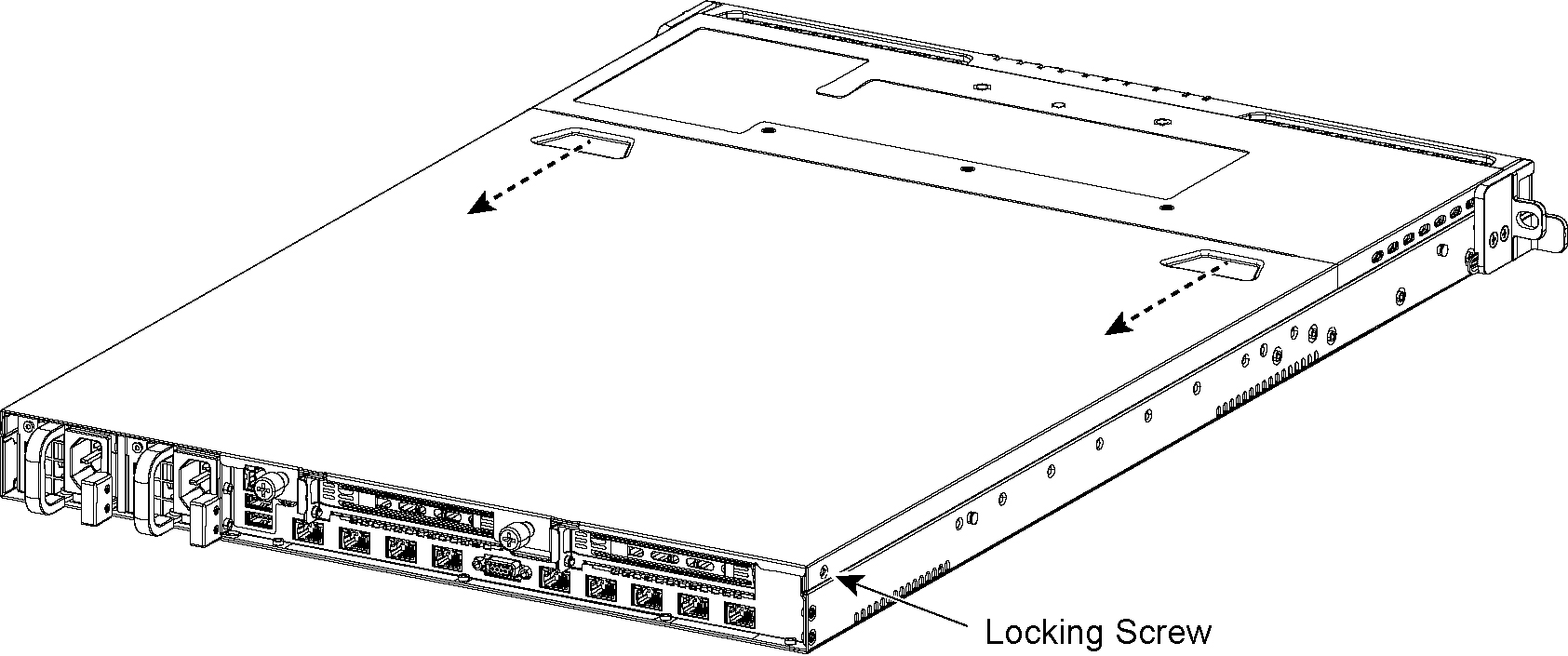
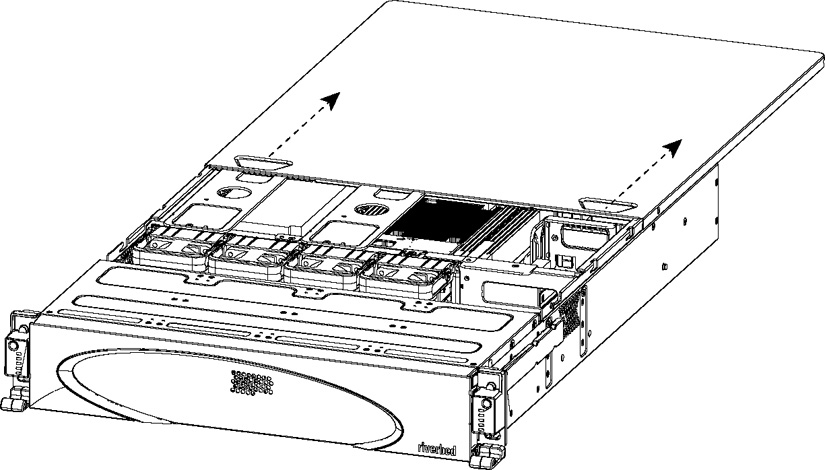
Figure: Removing the chassis cover
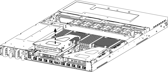
8. To release the PCIe carrier, remove the two locking screws.
Figure: Removing the PCIe carrier
10. Remove the two locking screws on the faceplate of the filler bracket on the rear panel of the PCIe carrier.
11. If you are replacing an existing NIC, carefully pull the NIC from the riser card.
Do not attempt to remove the onboard NIC built into the motherboard. The NICs fit horizontally into the PCIe carrier. The NIC connectors fit into the bus slots on the motherboard.
Figure: Removing the NIC from the ESD bag
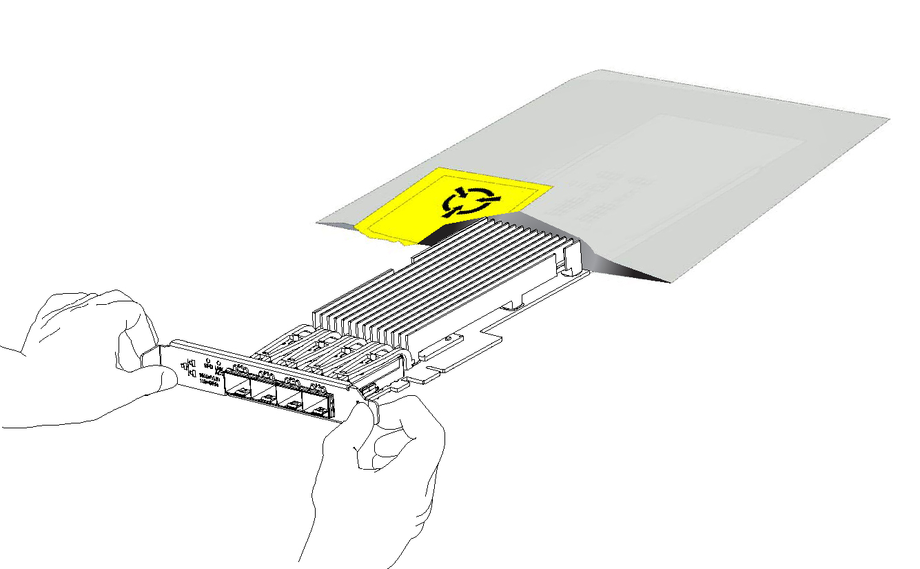
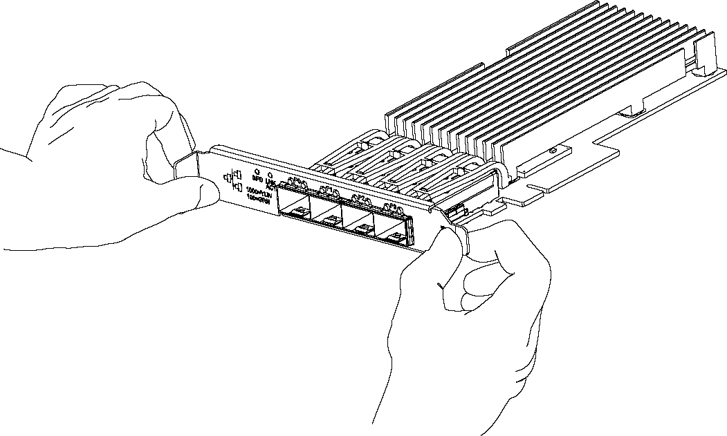
Figure: Proper handling of the NIC
14. Plug the new NIC into the slot on the PCIe carrier.
Note: Make sure the NICs are seated properly in the PCIe carrier. If they are not seated properly, NICs do not function.
15. Secure the NIC in the PCIe carrier at the back panel with the locking screws. When replacing the carrier, the metal peg must line up with the stand on the motherboard.
16. Replace the PCIe carrier in the chassis. Make sure that the NIC connectors fit securely into the bus slots on the motherboard and that the stand on the motherboard lines up with the peg on the PCIe carrier.
17. Replace the two retaining screws on the top of the PCIe carrier and the one screw on the rear panel.
18. Replace the cover on the chassis and tighten the locking screws at the back of the chassis.
19. Connect the power cords.
20. Connect the NIC cables.
21. Power on the appliance and check the status lights.
To test SteelFusion Edge NICs
1. Connect to the SteelFusion Edge CLI.
For detailed information, see the Riverbed Command-Line Interface Reference Manual.
2. Enter enable mode. At the system prompt, enter the following command:
amnesiac > enable
amnesiac #
3. Verify that the NIC is correctly installed.
To verify a Two-Port Gigabit Ethernet Copper PCIe card, use the show hardware all command:
amnesiac # show hardware all
Hardware revision: A
Mainboard: SteelFusion RiOS Motherboard 1U, 425-00218-01
Slot 1: .......... 2 Port Copper GigE Gen2 PCIe Non-Bypass Module, Integrated
Slot 2: .......... 4 Port NIC,PCIE,Bypass+LSi,Mitac, 410-00166-01
System led: Blue
amnesiac #
Installing NICs in 2U SteelFusion Edge appliances
This section describes how to install NICs in the 2U SteelFusion Edge appliances.
Figure: PCIe slot locations for 2U SteelFusion Edge appliances
To install a NIC in the 2U appliances
1. Power down the appliance.
2. Remove the power-supply cord and all cables connected to the appliance.
3. Remove the appliance from the mounting rack, if necessary.
4. Release the two locking screws on the back of the appliance to remove the cover. (See
Figure: Locking screws.)
Figure: Locking screws
5. Remove a third locking screw on the right side of the top cover.
Figure: Removing the rear top cover from the chassis
7. To release the PCIe carrier, remove the two retaining screws on the top of the carrier and the two retaining screws on the rear panel.
8. To remove the right or left PCIe carrier from the chassis, place your fingers in the carrier holes and lift straight up.
9. Turn over the carrier to reveal the PCIe slots.
PCIe cards fit horizontally in the carrier slots and are secured with screws in the rear panel. The connector at the bottom of the carrier fits into bus slots on the motherboard.
10. Remove the filler bracket on the rear of the PCIe carrier.
Figure: Removing the NIC from the ESD bag
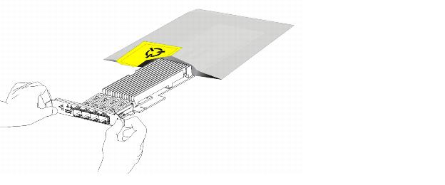
Figure: Proper handling of the NIC
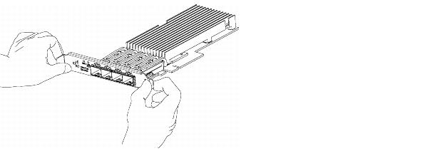
Figure: Installing the new NIC into the PCIe carrier
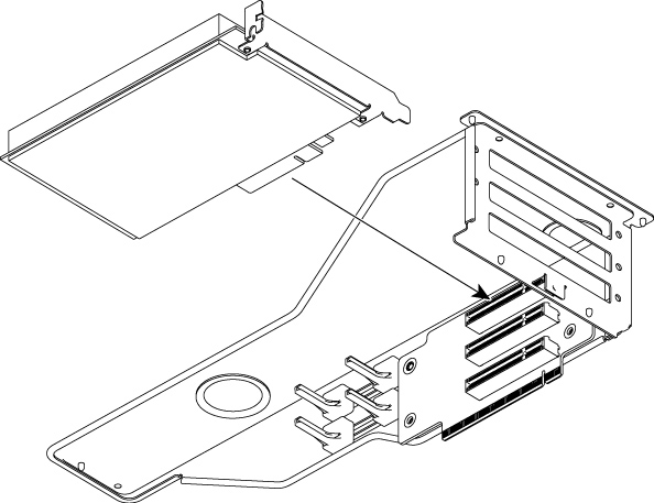
Note: Make sure the NICs are seated properly in the PCIe carrier. If they are not seated properly, the NICs do not function.
14. Replace the PCIe carrier in the chassis. Make sure that the carrier connectors fit securely into the bus slots on the motherboard.
15. Replace the two retaining screws on the top of the PCIe carrier and the one screw on the rear panel.
16. Replace the cover on the chassis and tighten the locking screws at the back of the chassis.
17. Connect the power cords.
18. Connect the NIC cables.
19. Power on the appliance and check the status lights.
To test NIC connections in the SteelFusion Edge
1. Connect to the SteelFusion Edge CLI.
For detailed information, see the Riverbed Command-Line Interface Reference Manual.
2. Enter enable mode. At the system prompt, enter the following command:
amnesiac > enable
amnesiac #
3. Verify that the NIC is correctly installed.
To verify a Four-Port Gigabit Ethernet Copper PCIe card, use the show hardware all command:
amnesiac # show hardware all
Hardware revision: A
Mainboard: SteelFusion RiOS Motherboard 2U 3.5, 425-00218-01
Slot 0: .......... 2 Port Copper GigE Gen2 PCIe Non-Bypass Module, Integrated
Slot 1: .......... 4 Port NIC,PCIE,Bypass+LSi,Mitac, 410-00166-01
Slot 7: .......... SteelFusion Backplane Interconnect, Integrated
Slot 8: .......... SteelFusion Backplane Interconnect, Integrated
Slot 9: .......... SteelFusion VSP Hardware Management Interconnect, Integrated
System led: Blue
amnesiac #
NIC self-test for SteelFusion Edge
The following self-test helps you verify that your card functions properly.
Before you begin, plug a crossover cable between the LAN and WAN on the SteelHead. With the service enabled and an IP address on the inpath0_0 interface, you will see a link on both interfaces.
To validate a Four-Port TX Copper Gigabit Ethernet Card
For the Four-Port TX Copper Gigabit Ethernet card, the LEDs are indicated by the following status lights:
• The Link/Activity LEDs are solid green when there is a link, and they blink to show network activity.
• The Bypass LEDs are solid green to indicate the card is in bypass mode.
• The Disconnect/LEDs are solid yellow in disconnect mode.
You must induce traffic to ensure the card works correctly. Removing the cable from the ports turns off the LEDs.
To induce traffic to verify the NIC
1. Connect to the Riverbed CLI.
For detailed information, see the Riverbed Command-Line Interface Reference Manual.
2. To check for connectivity, at the system prompt, enter the following ping command:
amnesiac > ping -c 1 -I <inpath-ipaddress> -b <broadcast-ip-address>
For example (where the netmask is /24):
amnesiac > ping -c 1 -I 10.11.128.8 -b 10.11.128.255
This ping command creates a loop for testing the appliance in isolation.
Network interface card status lights
The following table describes the status lights that appear on Riverbed network cards. For detailed information about the NICs see
Network Interface Cards
LED | Condition |
Link/Activity | Solid green (or yellow) on link. Blinks green (or yellow) on activity. Note: Some cards have separate link and activity LEDs. |
Speed 1G Cards | 1 Gb - Yellow or orange
100 M - Green
10 M - Off Blinks green on activity. |
Speed 10G Cards | 10 Gb - Green or blue
1 Gb - Yellow or orange
100 M - Off |
Bypass/Disconnect | Solid green in bypass mode. Solid yellow in disconnect mode. Note: Some cards share Bypass/Disconnect function with speed function when integrated in to RJ Connector LED will blink in this case. |